PPA F10R User manual

F10R REFLECTIVE PHOTOCELL DETECTOR
INSTRUCTION MANUAL
COMFORT AND SECURITY
INSTALLATION
X
F10R Reflective
photocell detector
PHOTOCELL DETECTOR FEATURES:
P04985 - Rev. 2
PRECAUTIONS
SPECIFICATIONS
- Max range: 08 meters (~26.25 feet)
- Operating voltage: 12Vdc - 24Vdc;
- Current drain: 80mA;
- NO and NC outputs;
- Immediate triggering;
- Pulsed output for PPA Control boards.
Round Reflector
Connection terminal
( + ) ( - ): The device must be powered
by a 12Vdc - 24Vdc auxiliary power
supply;
P: Pulsed output for PPA Control
boards;
NA, C and NF: Relay dry contact
outputs. Used for circuit keying
when the photocell is used in
normal mode, either open or closed.
Step 1: Attach the photocell detector the same side the control
board is installed, since it will both receive commands from it and
power it up. The receiver is attached the opposite side, with the
transmitter and receiver facing each other. When attaching the
round reflector, mind the (Installation) Position Indicator, it must
face up. ( ). The photocell detector must be attached so
that the opening for the wiring faces down, in order to
avoid accidental water entering.
A installation diagram can be seen on the previous page.
- Make sure the
wiring is facing down;
- Install the photocell
away from obstacles
which could block the
beam.
LED Indicator
Transmitter
Receiver
Wiring Position indicator
(for installation)
Step 2: Set the operation mode according to the
following procedures :
'Coded PPA' Mode:
NO (Normally Open) Mode:
NC (Normally Closed) Mode:
LED indicator on: Misaligned
or blocked sensor.
LED indicator off: optimal alignment.
LED indicator blinking: Function used for
installation; the blinking LED indicates
to the installer that the photocell detector
is sending the signal to the control board and
it is operating, but it is partially aligned, and
only needs a simple adjustment for optimal
alignment and proper operation.
NOTE: The slower the LED blinks, the closer to
the optimal alignment the photocell detector is;
if the LED starts blinking faster, it is less aligned.
'P' output of the photocell's connection terminal
connected to the 'FOT' output of the control board
'NA', 'C' and 'NF' outputs of the connection terminal
not connected.
'NF' output of the photocell's connection terminal
connected to the 'FOT output of the control board
'C' output of the photocell's connection terminal
connected to the ( - ) output of the control board.
'NA' output of the photocell's connection terminal
connected to the 'FOT' output of the control board
'C' output of the photocell's connection terminal
connected to the ( - ) output of the control board.
LED FUNCTIONS
F10R REFLECTIVE PHOTOCELL DETECTOR
INSTRUCTION MANUAL
STEP 3: Connect power to the
sensor by using an auxiliary power
supply, such as the control board.
Observe the polarity, the wires
must be connected to the auxiliary
power supply according to the
diagrams of the connection
terminal .
The height indicated by an “X” refers to the height of the
possible objects which will be detected by the device, such as
vehicles, people and pets. For example, for a 50cm (~1.65f) high
vehicle, the photocell detector must be installed over this
height, otherwise it will not detect the vehicle. One must
observe the minimum height (30 cm - ~0.99f), in order to both
ensure a proper operation and avoid false alarms.
Note: There is no maximum height for installing the photocell
detector.
ATIV/PASS Jumper: This jumper changes the relay operation
mode.
- Closed: Passive relay (Factory default setting).
- Open: Active relay (In this mode, the relay keeps activated
while the photocell detector is aligned, i.e., NO mode becomes
NC and vice versa).
COMFORT AND SECURITY

FOTOCÉLULA REFLEXIVA F10R
MANUAL DE INSTRUCCIONES
COMODIDAD Y SEGURIDAD
INSTALACIÓN
X
Fotocélula
Reflexiva F10R
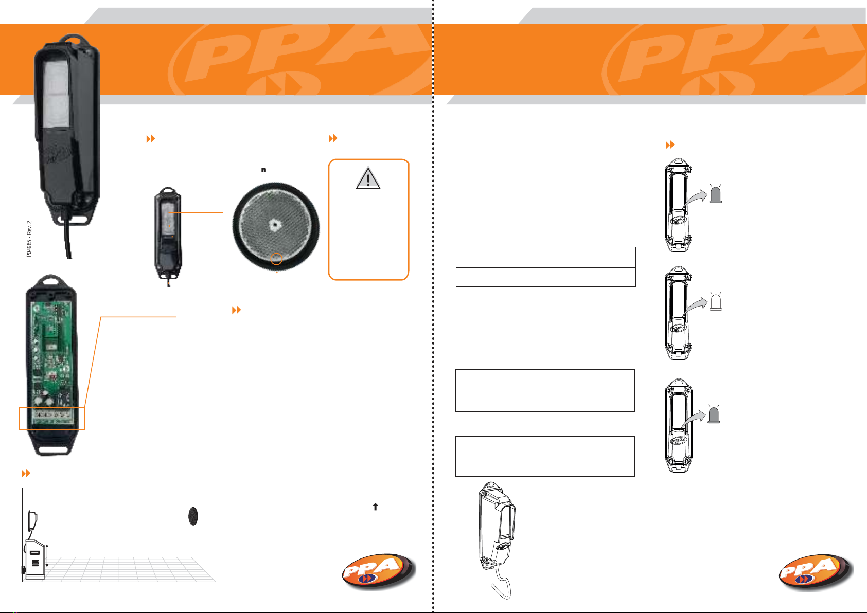
PRESENTACIÓN DE LA FOTOCÉLULA
P04985 - Rev. 2
PRECAUCIONES
DATOS TÉCNICOS
- Alcance máximo de: 08 metros
- Voltaje operativo: 12Vdc - 24Vdc;
- Consumo máximo de corriente: 80mA;
- Salida NA y NC;
- Accionamiento inmediato;
- Salida en impulsos para Centrales de mando PPA.
Espejo circular
Borne de Conexión
( + ) ( - ): La fotocélula poderá
alimentarse a partir de una fuente
de alimentación eléctrica auxiliar de
12Vdc - 24Vdc;
P: Salida en impulsos para centrales
de mando PPA;
NA, C y NF: Salidas de contacto seco
de un relé. Usado para conmutar el
circuito cuando se utilice la
fotocélula en modo normal abierta
o normal cerrada.
Paso 1: Fije la fotocélula en el lado en que esté posicionada la
central, pues la central va a recibir los comandos de accionamiento
de la fotocélula y probablemente la alimentará. La unidad
receptora es fijada en el lado opuesto, alineadas entre sí. Al fijar
el espejo circular, esté atento al Indicador de Posición de
Instalación; él debe quedar hacia arriba ( ). La fotocélula es
fijada de forma que la tapa por la que salen los cables de la
fotocélula quede hacia abajo, para evitar que entre agua en
el aparato.
- Asegúresee de que
la salida de los cables
está posicionada
hacia abajo;
- Instale la fotocélula
lejos de obstáculos
que puedan bloquear
el haz.
LED Indicador
Emisor
Receptor
Salida de cables Indicador de posición
de instalación
Paso 2: Configure el modo de operación de la
fotocélula de acuerdo a las instrucciones abajo:
Modo 'PPA Codificada':
Modo NA (Normalmente Abierta):
Modo NC (Normalmente Cerrada):
LED indicador encendido: Fotocélula
desalineada o bloqueada.
LED indicador apagado: Fotocélula
alineada y no bloqueada.
LED indicador parpadeando: Función usada
para instalación, cuando el LED parpadea,
eso indica al instalador que la fotocélula está
enviando la señal para la central de mando y
funcionando, pero está parcialmente alineada,
y sólo necesita de un simple ajuste para
alineación óptima y funcionamiento correcto.
NOTA: Cuanto más lento el LED parpadea,
más cerca del alineamento perfecto está la
fotocélula, si el LED empieza a parpadear a
parpadear más rápidamente, es sabido que
la Fotocélula está menos alineada.
Salida 'P' del borne de conexión de la fotocélula conectada
a la salida 'FOT' de la central de mando
Salidas 'NA', 'C' y 'NF' del borne de conexión de la fotocélula
desconectadas.
Salida 'NF' del borne de conexión de la fotocélula
conectada a la salida 'FOT' de la central de mando
Salida 'C' del borne de conexión de la fotocélula
conectada a la salida ( - ) de la central de mando.
Salida 'NA' del borne de conexión de la fotocélula
conectada a la salida 'FOT' de la central de mando
Salida 'C' del borne de conexión de la fotocélula
conectada a la salida ( - ) de la central de mando
FUNCIONES DEL LED
FOTOCÉLULA REFLEXIVA F10R
MANUAL DE INSTRUCCIONES
Paso 3: Conecte la fotocélula a una
fuente de alimentación eléctrica
auxiliar, por ejemplo, por la central
de mando.
Observe la polaridad, los cables
deben estar conectados a la fuente
auxiliar de acuerdo a los diagramas
del borne de conexión.
En la página anterior se puede ver el diagrama de instalación
del producto. La altura “X” mostrada en la imagen es la altura de
lo que deseamos proteger, como coches, personas y mascotas.
Por ejemplo, para un coche con altura de 50cm, debemos
instalar la fotocélula por arriba de esta altura, de lo contrario el
sensor no detectará el coche. Se debe respectar la altura
mínima de 30cm, para garantizar el funcionamiento correcto
del producto y evitar falsas alarmas.
Nota: No hay altura máxima para instalación de la fotocélula.
Jumper ATIV/PASS: Este jumper invierte el estado de
funcionamiento del relé.
- Cerrado: Relé Pasivo (Configuración de fábrica).
- Abierto: Relê Activo (En ese modo, el relé queda activado
mientras la fotocélula esté alineada, es decir, NA se convierte
en NC y viceversa).
COMODIDAD Y SEGURIDAD
Table of contents
Languages:
Other PPA Accessories manuals
Popular Accessories manuals by other brands

Hytronik
Hytronik HIM38/RF Installation and instruction manual

Gigaset
Gigaset Smart Doorbell quick start guide

PCB Piezotronics
PCB Piezotronics 261A01 Installation and operating manual

Kathrein
Kathrein ESD 44 quick start guide

BDI
BDI PSW-100 Operation Quick Start Guide

Crivit Beach
Crivit Beach SWIMMING GOGGLES Instructions for use