PPS PPS71 User manual

PPS71 GEOTHERMAL MEMORYTOOL
User Manual (MAN-0011 Rev. 04)

PPS71 Geothermal Memory Tool User Manual Page | 2
MANU-0011 R03
REVISION HISTORY
Revision
Date
Comments
01
2015-08-12
Combined Geothermal Memory Gauge with GRD user manual Rev. 06 and Geothermal
Memory Gauge user manual Rev. 09. Replaced draft system user manual (MANU-0011)
Rev 01 & 02. Updated specifications, formatting, module information and imagery. The
following history from previous manuals have been transferred:
2010-08-20 R01 Initial release
2010-12-15 R02 Information about maintenance of spinner
2011-01-13 R03 More Information about operation time and maintenance
2011-02-07 R04 More Information about flask test
2011-07-27 R05 Update for maintenance tool kit
2011-09-19 R06 Update for specification
2012-01-31 R07 Update for description about accessories
2013-06-12 R08 Updated specification. Updated information about setting the type
of spinner by SmartLog; Updated parts list for gauge, accessories,
options and maintenance kit
2013-11-07 R09 Information about how to install spinner and disassemble flask
Housing
02
2017-08-02
- Reference to EC17-0005
- Added PPS71 Pt & PTS Tools and renamed tool names in Appendix A, E.
- Added PPS71 Quartz & Inconel to Appendix F
- Updated Part name to item 1 in Appendix G
-Added PT, PTS and Quartz to Appendix J
- Updated section 1.3
03
2019-10-25
- More information about using centralizer with 1.69” spinner
04
2022-04-26
Reference to EC22-0003.
Updated tool with new 3-reed TPS sub (01-AC-2676-A) and 7/16-28UNEF pressure
filter (01-AC-2181-A).

PPS71 Geothermal Memory Tool User Manual Page | 3
MANU-0011 R03
REVISION HISTORY.................................................................................................................................................2
1. INTRODUCTION ................................................................................................................................................5
1.1. OBJECTIVE...........................................................................................................................................................5
1.2. OVERVIEW ..........................................................................................................................................................5
1.3. CONFIGURATIONS.................................................................................................................................................5
PPS71 PT..................................................................................................................................................5
PPS71 PTS................................................................................................................................................6
PPS71 PTS-C ............................................................................................................................................6
PPS71 ELITE .............................................................................................................................................6
PPS71 QUARTZ ........................................................................................................................................6
1.4. APPLICATIONS......................................................................................................................................................7
1.5. PRIMARY FEATURES ..............................................................................................................................................7
1.6. RESPONSIBLE PERSONNEL ......................................................................................................................................7
2. GETTING STARTED............................................................................................................................................8
2.1. TESTING THE FLASK HOUSING .................................................................................................................................8
2.2. INSTALLING SMARTLOG .......................................................................................................................................10
To install PPS SmartLog software from the CD/USB: ............................................................................10
2.3. ATTACHING SPINNER...........................................................................................................................................11
Attaching a Spinner...............................................................................................................................11
Attaching a Centralizer & Spinner Combo ............................................................................................12
Attaching a Centralizer on 1.69” Spinner..............................................................................................13
Attaching a Bullnose - No Flow Profile..................................................................................................14
2.4. SETTING THE SPINNER TYPE IN THE TOOL STRING......................................................................................................15
Spinner Configuration ...........................................................................................................................17
Impeller Pitch ........................................................................................................................................17
Flow Direction .......................................................................................................................................18
Spinner Outside Diameter.....................................................................................................................18
2.5. RUNNING DIAGNOSTICS.......................................................................................................................................19
Bench Test Pressure & Temperature ....................................................................................................19
Bench Test CCL......................................................................................................................................20
Bench Test Gamma Ray Detection........................................................................................................20
Bench Test Flow Profile.........................................................................................................................22
2.6. PROGRAMMING ATOOL ......................................................................................................................................23
2.7. ADDING A BATTERY.............................................................................................................................................24
Activate and test battery.......................................................................................................................24
Test battery with module......................................................................................................................25
2.8. ADDING A HOUSING (1.75” OD TOOL)..................................................................................................................26
2.9. ADDING A HOUSING (1.56” OD TOOL)..................................................................................................................30
2.10. FILLING THE SPINNER WITH OIL..............................................................................................................................33
2.11. REMOVING THE HOUSING (1.75” OD TOOL) ..........................................................................................................35
2.12. REMOVING THE HOUSING (1.56” OD TOOL) ..........................................................................................................36

PPS71 Geothermal Memory Tool User Manual Page | 4
MANU-0011 R03
2.13. DOWNLOADING DATA .........................................................................................................................................38
3. MAINTENANCE...............................................................................................................................................40
3.1. CHANGE PRESSURE FILTER ....................................................................................................................................40
3.2. ASSEMBLY,DISASSEMBLY AND CLEANING THE 2.125” OD SPINNER ............................................................................41
Disassembly and Cleaning of the 2.125”/1.69” OD Spinner (for 1.75” OD Flask).................................41
Assembly of the 2.125” and 1.69” OD Spinner (for 1.75” OD Flask).....................................................43
3.3. ASSEMBLY,DISASSEMBLY AND CLEANING THE 1.44” OD SPINNER ..............................................................................45
Disassembly and Cleaning of the 1.44” OD Spinner (for 1.56” OD Flask) .............................................45
Assembly of the 1.44” OD Spinner (for 1.56” OD Flask) .......................................................................47
3.4. VIEWING SPINNER MAINTENANCE VIDEOS ..............................................................................................................49
3.5. MANUFACTURER'S MAINTENANCE.........................................................................................................................50
4. TROUBLESHOOTING .......................................................................................................................................51
APPENDIX A: PPS71 MEMORY TOOL PART NUMBERS.......................................................................................... 52
APPENDIX B: MAINTENANCE KIT (FOR 1.75” OD).................................................................................................53
APPENDIX C: MAINTENANCE KIT (FOR 1.56” OD)................................................................................................. 54
APPENDIX D: THERMOMETER PART NUMBERS.................................................................................................... 54
APPENDIX E: PPS71 TOOL & ACCESSORIES (PT, PTS, PTS-C; 1.75” OD) .................................................................55
APPENDIX F: PPS71 TOOL & ACCESSORIES (ELITE, QUARTS, 1.75” OD)................................................................. 56
APPENDIX G: PPS71 TOOL & ACCESSORIES (ELITE 1.56” OD WITH GRD)............................................................... 57
APPENDIX H: SPINNER ACCESSORIES PART NUMBERS ......................................................................................... 59
APPENDIX I: PARTS TO CONVERT A MEMORY TOOL TO AN SRO TOOL................................................................. 60
APPENDIX J: SPECIFICATIONS............................................................................................................................... 61
APPENDIX K: DIAGRAM .......................................................................................................................................65
APPENDIX L: LIST OF IMAGES............................................................................................................................... 66

PPS71 Geothermal Memory Tool User Manual Page | 5
MANU-0011 R03
1. Introduction
1.1. OBJECTIVE
This manual explains the general operation of the PPS71 Geothermal Memory Tool. It can provide those
working with the tool the necessary knowledge and skills for programming, deployment, retrieval, and data
extraction (downloading of data files from the tool). All personnel involved in the process of operating
thePPS71 geothermal tools, should familiarize themselves with the detailed procedures outlined in this
manual.
This manual includes important information about the operation of PPS71
geothermal tools. Please read it carefully before operating the tools.
PPS SmartLog software is used with the PPS71 geothermal tools. This manual will cover some of the basic
steps using the software to prepare the tool for operations; however will not cover all of the software's
capabilities in detail. Please refer to the software manual for further instructions on advanced features.
1.2. OVERVIEW
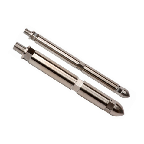
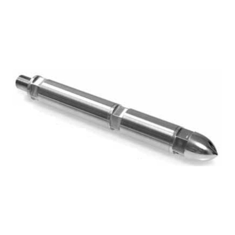
The PPS71 geothermal tool is designed for extreme, high temperature downhole conditions. The tool can
measure pressure, temperature, casing collar locations, gamma ray (optional) and Flow Profile (optional).
The robust electronics combined with vacuum flask technology allow the tool to perform at
350 °C (662 °F)* continuously, for four hours. The main component of the PPS71 geothermal tool is the
Memory module. The module is protected by a flask (Heat Shield Inner Tube) housing for operations up to
350 °C*, or a regular housing for operations up to 177 °C.
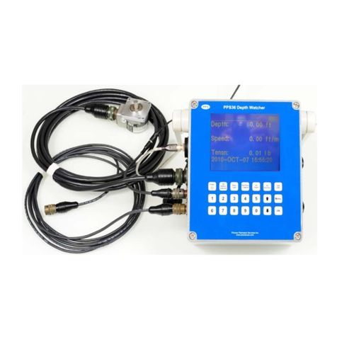
The tool can be run in the traditional mode (pressure and temperature) or run in conjunction with a depth
recorder (such as the PPS36 DepthWatcher which records depth, speed, time and tension) to incorporate
depth with downhole data, thereby becoming a mini-logging tool.
1.3. CONFIGURATIONS
PPS71 PT
The PPS71 PT Geothermal Tools are designed for extreme, high temperature downhole conditions. The
robust electronics combined with vacuum flask technology allow these products to perform at 350 °C (662
°F) continuously, for four hours. The tool measures pressure and temperature, and can be configured as
either a memory tool or surface read out (SRO) tool. The measurements are done with a highly sensitive
silicon-sapphire (Piezo) transducer and a resistance temperature detector (RTD). The RTD is exposed to
the well fluids for faster response and higher accuracy

PPS71 Geothermal Memory Tool User Manual Page | 6
MANU-0011 R03
PPS71 PTS
The PPS71 PTS Geothermal Tools are designed for extreme subsurface conditions. The robust
electronics combined with vacuum flask technology allow these products to perform at 350 °C (662 °F)
continuously, for four hours. The PTS tool measures pressure, temperature, and flow profile and can be
configured as either a memory tool or surface read out (SRO) tool. The measurements are done with a
highly sensitive silicon-sapphire (Piezo) transducer, a fast response resistance temperature detector (RTD)
and the customer’s choice of either a continuous or full-bore spinner flowmeter. Both continuous and full-
bore spinners are intended for quantitative use in flow streams with the spinners’ greatest quantitative
application being injection profiling.
PPS71 PTS-C
The PPS71 PTS-C Geothermal Tools are designed for extreme subsurface conditions. The robust
electronics combined with vacuum flask technology allow these products to perform at 350 °C (662 °F)
continuously, for four hours. The tool measures pressure, temperature, casing collar location, and flow
profile and can be configured as either a memory tool or surface read out tool (SRO) tool. The
measurements are done with a highly accurate silicon-sapphire (Piezo) transducer, a fast response
resistance temperature detector (RTD), and the customer’s choice of either a continuous or full-bore
spinner flowmeter and a highly sensitive CCL. The CCL has a magnet and central coil arrangement which
amplifies current providing a readable voltage spike or “collar kick” as data, giving end users an important
control for depth correlation.
PPS71 ELITE
The PPS71 Elite Geothermal Tools are designed for extreme, high temperature downhole conditions.
The robust electronics combined with vacuum flask technology allow these products to perform at 350 °C
(662 °F) continuously, for four hours. The tool measures pressure, temperature, casing collar location, flow
profile and gamma rays, and can be configured as either a memory tool or surface read out tool (SRO)
tool. The measurements are done with a highly accurate silicon-sapphire (Piezo) transducer, a fast
response resistance temperature detector (RTD), a continuous or full-bore spinner flowmeter, magnetic
CCL and sensitive gamma ray crystal which detects incoming gamma rays from the formation.
PPS71 QUARTZ
The PPS71 Quartz Geothermal Tools are designed for extreme, high temperature downhole conditions.
The robust electronics combined with vacuum flask technology allow these products to perform at 350 °C
(662 °F) continuously, for four hours. The tool measures pressure, temperature, casing collar location, flow
profile and gamma ray, and can be configured as either a memory tool or surface read out tool surface
read out tool (SRO) tool. The measurements are done with a superior quartz transducer, a fast response
resistance temperature detector (RTD), a continuous or full-bore spinner flowmeter, magnetic CCL and
sensitive gamma ray crystal. By combining the downhole measurements with PPS’s DepthWatcher
(PPS36), a depth versus time recorder, customers have the capability to create synchronized profile logs
which have many applications for the end user such as monitoring radioactive tracers in injected fluids,
interpreting lithology, estimating shale volume and correlating cores with logged depth.
* Note: 350°C for 1.75” OD flask

PPS71 Geothermal Memory Tool User Manual Page | 7
MANU-0011 R03
FRAGILE! If the tool includes a flask housing - PLEASE HANDLE WITH CARE!
1.4. APPLICATIONS
Steam Injection Profile Logging
Geothermal Well Test
Real-time Pressure Build-Up Tests
Real-time Pressure and Temperature Gradients
Tubing and Casing Leak Detection
Fluid Production/Injection Profiles
1.5. PRIMARY FEATURES
Memory logging capabilities
Fast data transfer @10samples/sec
Robust electronics and vacuum flask technology for outstanding performance at 350°C (662°F)*
Creates complete profile logs when used in conjunction with PPS36 DepthWatcher
Performs as an exceptional pressure and temperature tool when ordered without gamma and
spinner
Can be used as a temperature tool with a regular housing (up to 177°C)
The tool automatically recognizes bidirectional flow
Advanced customer support with online maintenance and software tutorials available
1.6. RESPONSIBLE PERSONNEL
All personnel, such as Field Supervisors, Field Engineers and Field Service Managers involved in the process
of running PPS71 Geothermal Tools, and acquiring job data from the tools should familiarize themselves with
the operational instructions included in this manual. Failure to do so may result in non-optimum job data or
tool damage.
* Note: 300°C for 1.56” OD flask

PPS71 Geothermal Memory Tool User Manual Page | 8
MANU-0011 R03
2. Getting Started
This is a quick overview of the steps necessary to get started with a PPS71 Geothermal Memory Tool. For
more details on any particular step please refer to that expanded section of the manual.
(1) Test the flask housing for heat protective capabilities
(2) Install SmartLog software
(3) Attach and configure the spinner if recording Flow Profile, or a bullnose if not
(4) Run diagnostics on the tool using SmartLog software
(5) Program the tool
(6) Add a battery
(7) Install the housing (either flask or standard)
(8) Fill the spinner with (high temperature) hydraulic oil
(9) Run the job(s)
(10) Disassemble tool
(11) Attach a computer using the USB cable and download job data
It is essential to test and inspect the flask housing prior to any
operation. If the flask is damaged or fails the temperature test please
contact PPS immediately and DO NOT run the tool, as this could result in
permanent irreparable damage.
2.1. TESTING THE FLASK HOUSING
To ensure optimum performance of the flask (Heat Shield Inner Tube) and proper protection for the module,
regular inspection of the flask is necessary and PPS recommends testing the flask before EVERY operation. To
properly test the flask you'll need an RTD thermometer (0 –100°C, Error < ±0.5°C, Resolution 0.1°C) as the
test measurement instrument and the ambient temperature should be between 20 to 30°C.
Figure 1 - RTD thermometer and heat insulator for testing

PPS71 Geothermal Memory Tool User Manual Page | 9
MANU-0011 R03
(1) Begin by boiling five litres (5L) of water to the boiling point (100°C)
(2) Fill the flask with the boiled water to 10-cm below the top of the flask
Figure 2 - Water level for flask testing
(3) Sink the RTD probe into the top of the flask, sealing it with the heat isolator
Figure 3 - Insert RTD probe into the flask and seal with heat insulator
(4) Start recording the RTD temperature readings every three (3) minutes for the next fifteen (15)
minutes
(5) After fifteen (15) minutes subtract the temperature at 15 minutes from the start temperature
in order to calculate the temperature difference, as illustrated in the chart below.

PPS71 Geothermal Memory Tool User Manual Page | 10
MANU-0011 R03
The temperature difference should be no greater than 16°C / 30°F after the
first 15 minutes of the test.
Test Sample
Elapsed Time (min.)
Temp. °C
Temp. °F
0
81.40
178.52
3
80.88
177.58
6
80.24
176.43
9
79.79
175.62
12
79.55
175.19
15
79.33
174.79
Temp. Difference @ 15 min
2.07
3.73
Figure 4 –Calculating temperature difference when testing the flask
(6) Remove the RTD probe and the heat isolator
(7) Empty the water out of the flask
(8) Let the flask air dry
2.2. INSTALLING SMARTLOG
Before installing the SmartLog software, you should have your computer system ready with any one of the
following operating systems: Windows 2000/XP/Vista/7/8/10.
The SmartLog software CD or USB drive in the shipping package contains all the files you need to install the
program. Alternatively, registered customers can download the latest version from our web site at
www.pioneerps.com.
To install PPS SmartLog software from the CD/USB:
(1). Connect the USB drive or Insert the CD into your CD drive.
(2). To view the contents, click the My Computer icon on your computer desktop or in the
Start Menu and then choose the Compact Disc, DVD, or USB icon.
(3). Double click the Setup.exe icon to launch the SmartLog installation.
(4). Follow the instructions leading you to finish the installation process.
Figure 5 - PPS SmartLog software shortcut

PPS71 Geothermal Memory Tool User Manual Page | 11
MANU-0011 R03
2.3. ATTACHING SPINNER
The next step in preparing for field operations is attaching the spinner or spinner/centralizer combo in order
to measure Flow Profile.
If you are not measuring Flow Profile, you can skip to the instructions for
attaching a bullnose or centralizer.
Attaching a Spinner
Figure 6 - Insert the spinner into the memory module
Figure 7 - Hand screw the spinner onto the pressure sub
The spinner is attached to the pressure sub as seen in the previous figures. Start by screwing the
spinner on by hand. Finish tightening the spinner using two wrenches as per the next figures.
Place one wrench at position A and the other at position B. Use the open-end wrench at position
A to stabilize the module and the open-end wrench at position B to tighten the spinner. See
below for wrench sizes:

PPS71 Geothermal Memory Tool User Manual Page | 12
MANU-0011 R03
Tool OD
Position
Wrench Size
1.75”
A
1 –5/8”
B
1 –1/2"
1.56”
A
1 –3/8”
B
1 –1/4"
Figure 8 –Wrench sizes for connecting spinner to pressure sub
Figure 9 - Positions for the wrenches to tighten the spinner
Attaching a Centralizer & Spinner Combo
Figure 10 - Insert the centralizer into the memory module
Note: The centralizer shown in Figure 10 is combined with a spinner.

PPS71 Geothermal Memory Tool User Manual Page | 13
MANU-0011 R03
Figure 11 - Hand tighten the centralizer in place
The centralizer is attached to the pressure sub. Start screwing on the centralizer by hand. Then
tighten the centralizer using two open-end wrenches. Place one wrench (1-5/8”) at position A as
seen in the figure above, then place the second open-end wrench (1-1/2”) on the wrench flat on
the centralizer.
Attaching a Centralizer on 1.69” Spinner
(1) Remove the bullnose of spinner
(2) Apply anti-sieve to the threads of the centralizer
(3) Hold the spinner by hand as shown below, make up or break apart the connection by
tapping the end wrench gently with a hammer.
(4) Apply safety wiring through ribs, twisting and terminating approximately as shown below.
Use Inconel 600, 0.032” DIA wire, the direction that the wiring lays –CRITICAL.
DO NOT USE THESE FALTS
FOR MAKING OR BREAKING
THE SHROUD TO SHROUD
CONNECTION.
HOLD BY HAND IN THIS AREA
USE 1-9/16” OPEN END WRENCH HERE

PPS71 Geothermal Memory Tool User Manual Page | 14
MANU-0011 R03
Attaching a Bullnose - No Flow Profile
Figure 12 - PPS71 bullnose
Figure 13 - Attaching the bullnose to the memory module
The bullnose is attached to the pressure sub as seen in the previous figures. Start screwing on
the bullnose by hand. Finish tightening the bullnose using two wrenches as per the next figures.
Place one wrench at position A and the other at position B (on bullnose). Use the wrench at
position A to stabilize the module and the other wrench at position B to tighten the bullnose.
See below for wrench sizes:
Tool OD
Position
Wrench Size
1.75”
A
1 –5/8”
B
1 –1/2"
1.56”
A
1 –3/8”
B
1 –3/8"
Figure 14 –Wrench sizes for connecting bullnose to pressure sub
Figure 15 - PPS71 bullnose

PPS71 Geothermal Memory Tool User Manual Page | 15
MANU-0011 R03
2.4. SETTING THE SPINNER TYPE IN THE TOOL STRING
Using a USB cable, connect the Memory module to a computer.
Figure 16 - PPS71 Geothermal memory module without gamma
Figure 17 - Six pin USB Cable
Use a six pin 3.6VDC USB cable for Memory Module without Gamma Ray Detector.
Use a four pin 7.2VDC USB cable for Memory Module with Gamma Ray detector.
Figure 18- PPS71 Geothermal memory module with gamma ray detector
Figure 19 - Four pin USB Cable
Once the module is connected, open the SmartLog software on the computer. The Tool String
settings found under the Options page in SmartLog, display the position and length
measurements of the different components of the Memory Tool. SmartLog can determine the

PPS71 Geothermal Memory Tool User Manual Page | 16
MANU-0011 R03
tool string for known tool configurations; however it may be necessary to modify these items
manually. Any item in the grid can be modified at any time.
Figure 20 - SmartLog Options Page; Tool String
Figure 21 - Tool string settings
Please Check the SmartLog manual for detailed instructions on adjusting Data
Type, Offset, and what it means to include the Tool String in a Merged Run. For
now you'll be adjusting the Spinner configuration, pitch, impeller direction and
minimum diameter.

PPS71 Geothermal Memory Tool User Manual Page | 17
MANU-0011 R03
Spinner Configuration
Spinner configuration is the type of spinner attached to the tool, with spinner types being
interchangeable. The Tool String offsets are measured from the bottom of the tool, and the
spinner is located at the bottom. This means a change in spinner type will affect the offsets of the
other components. Therefore the spinner type options must be set to correspond with the
physical spinner type connected to the tool.
Select the appropriate spinner type from the drop-down list and click the Apply Type button.
This will adjust the tool string offset values in SmartLog to account for the different spinner.
If the spinner type does not appear in the list, select Custom and enter the Spinner Length and
Impeller Offset manually. The Spinner Length is the distance from the bottom of the spinner to
the pressure port. The Impeller Offset is the distance from the bottom of the spinner to the
impeller.
Figure 22 - Spinner configuration window
Impeller Pitch
Also, important when replacing the spinner is the impeller pitch. This value indicates the
inches/per revolution in relation to the physical spins of the impeller. This is often a one to one
ratio where one spin equals one rotation, but in certain circumstances you may need a spinner
that spins slower or faster before registering a rotation. This is where the pitch can be useful.
The pitch value depends on the impeller. To determine the pitch, refer to the impeller
specifications or contact the vendor. Select the pitch value from the drop-down list:
Figure 23 - Spinner pitch drop down menu
If the impeller’s pitch value is not listed, select Custom, and enter the Spinner Multiplier
manually. In this case, the spinner multiplier is the value that must be multiplied with the
impeller’s pitch in order to get standardized rotations/second. This value is normally: (pitch/5).

PPS71 Geothermal Memory Tool User Manual Page | 18
MANU-0011 R03
Flow Direction
The spinner values represent the rate of spins as well as the rotation direction. During Normal
operation the values will be positive when the impeller rotates in one direction and negative for
the other direction. Select Inverted to have the values read opposite for the corresponding
direction.
Spinner Outside Diameter
The Spinner OD (outside diameter) is automatically updated based on the spinner selected, but
if using another spinner type, ensure the Spinner OD is updated according to the spinner
dimensions.
After the spinner information is updated, click OK to close the Job Information. If the spinner
information has been changed then you will see the following request:
Figure 24 - Saving spinner type
Click Yes to save the information to the tool. This will allow the tool to remember the
information for the spinner that is connected to it, so you will not have to re-enter it again in the
software later.

PPS71 Geothermal Memory Tool User Manual Page | 19
MANU-0011 R03
2.5. RUNNING DIAGNOSTICS
The PPS SmartLog software diagnostics confirm that the module measures pressure, temperature, CCL,
gamma (optional) and Flow Profile (optional). This manual will cover the basics on diagnostics and
programming.
For more information about the software, please refer to the SmartLog Software
Manual, Section 7.14 for Diagnostics and Section 6.2 for Programming.
Select “Diagnostics” under the Options Tab.
Figure 25 - Screenshot of SmartLog Diagnostics
Bench Test Pressure & Temperature
From the drop down menu select the sampling rate. Then run a bench test on the Pressure and
RTD temperature by clicking the “Start” button. Samples should be generating at the rate
selected.

PPS71 Geothermal Memory Tool User Manual Page | 20
MANU-0011 R03
Figure 26 - Diagnostics sampling rate drop down menu and start button
Bench Test CCL
Next do a CCL test. Using a metal screwdriver, touch the CCL section of the module. The reading
in the Diagnostics panel will show that the CCL is functioning.
Figure 27 - Testing CCL to check the reading in Diagnostics panel
Bench Test Gamma Ray Detection
If you are not measuring gamma, you can skip this step.
Other manuals for PPS71
1
Table of contents
Other PPS Measuring Instrument manuals
Popular Measuring Instrument manuals by other brands
ADA INSTRUMENTS
ADA INSTRUMENTS ZHM 125B operating manual

PCB Piezotronics
PCB Piezotronics 353B12 Installation and operating manual

KROHNE
KROHNE OPTIPROBE quick start
TA Instruments
TA Instruments TMA 2940 Operator's manual

Squirrel
Squirrel MUTATION 2 user manual
GLI International
GLI International Accu4 Operating instructions manual
Sper scientific
Sper scientific 800048 instruction manual
ATI Technologies
ATI Technologies 2i Operation and maintenance manual

Anritsu
Anritsu MS2690 Operation manual

WATANABE ELECTRIC INDUSTRY
WATANABE ELECTRIC INDUSTRY AL-512 Series instruction manual
Itm
Itm Megger MPQ1000 user manual
Sprague
Sprague TO-6 operating manual
