PRÜFTECHNIK VIB 6.195 Owner's manual

Accelerometer (Wind)
VIB 6.195
Installation and Operation

2
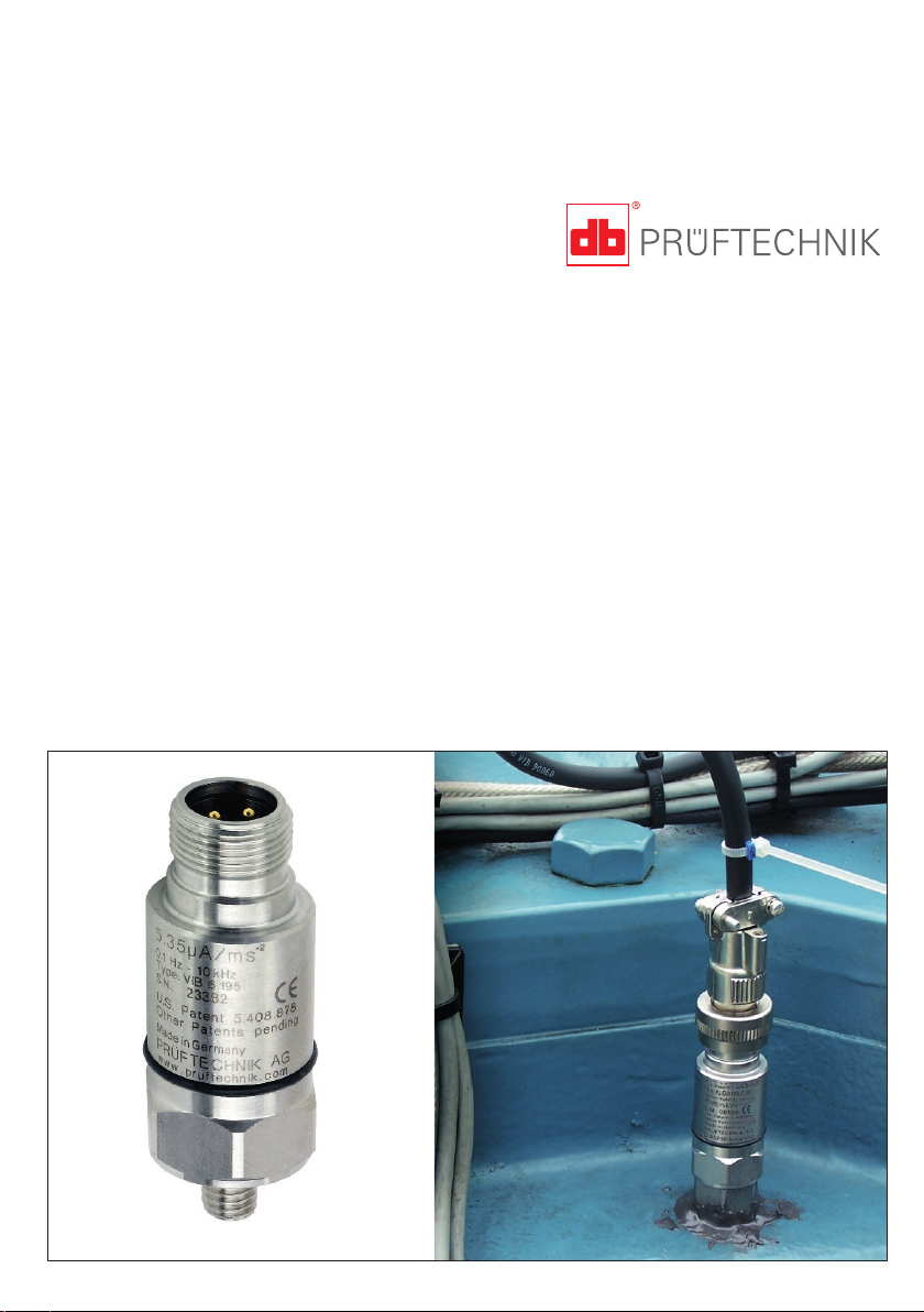
Accelerometers of the VIB 6.195 series are used
for the measurement of absolute casing vibrations
on machinery with rotating components. Due to
the very low limit frequency, the accelerometers
are particularly suitable for very slowly rotating
components (n >6 rpm) such as the main bear-
ings of a wind turbine.
The accelerometers have a current linedrive out-
put (CLD).
Safety Information
• Read these operating instructions carefully and
store them.
• Observe the operating instructions of the con-
nected devices.
• Read and observe the safety information in
these operating instructions!
• Only use the accelerometer as intended and for
the permitted purpose of application.
• Use original accessories only.
• Replace defective accelerometers and cables.
• Installation by qualified personnel only.
• Comply with the applicable safety regulations
when performing installation work on running
machines.
• Comply with the applicable safety regulations
when laying cables.
• Observe the technical data and the allowed
operating conditions. In case of doubt, consult
with PRUFTECHNIK.
• The accelerometer is in compliance with Eu-
ropean Directive 2004/108/EC. The complete
Declaration of Conformity is available at www.
pruftechnik.com.
Repair and Maintenance
The operation of the accelerometer is mainte-
nance-free. A repair is not possible.
Disposal
Dispose of the accelerometer after use in accor-
dance with applicable national regulations.
Mounting
The frequency response and dynamic range of an
accelerometer can be greatly influenced by the
installation. Poor coupling to the measurement
location can adversely affect the signal and restrict
the frequency range. In principle, the accelerome-
ter needs a non-positive, resonance-free and rigid
fastening to the measurement location, especially
for measurements with high frequencies.
The most secure and stable coupling is provided
by a screwed mounting, for which a M8 thread-
ed pin is attached to the accelerometer base by
default. For this accelerometer series, depending
on the requirements on site, various mounting
adapters are available as an accessory.
Mounting adapters
– Screw adapter M8-90°, VIB 3.437
(h*= 4)
– Screw adapter M5-flat, VIB 3.439
(h*= 1)
– Bonded adapter, VIB 3.433 (h*= 8)
– Magnetic holder, VIB 3.423 (h*= 10)
* h: Installation height in mm, only adapter
Accelerometer / Screw adapter
Required tools and resources
– Hand-held drill
– Drill bits with depth gauge (4.2 mm /6.8mm)
– Thread tap (M8/M5)
– 90°-countersink (for VIB 3.437)
– Torque wrench, SW22
– Compressed air for cleaning out the hole
– Solvent for degreasing
– Threadlocker (e.g., LOCTITE 243)
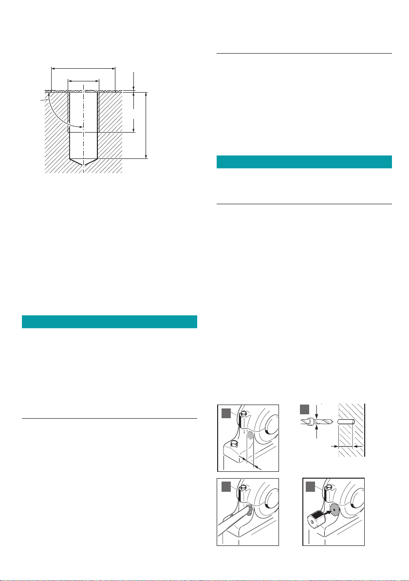
• Drill the mounting hole and cut the thread.
Thread hole for screw adapter VIB 3.437

3
Thread hole for accelerometer VIB 6.195
Dimensions in mm
17
12
Ø 27
M8
90°
0,5±0,2
• Clean the contact surfaces of the accelerometer
/ adapter and of the machine with solvent.
• Allow the contact surfaces to dry.
• Apply a thin film of threadlocker (LOCTITE 243)
to improve signal transmission.
• Screw in the accelerometer / adapter and tight-
en with a wrench.
Maximum torque:
– 11 Nm, accelerometer VIB 6.195 w/ M8 thread
– 11 Nm, adapter VIB 3.437
– 3 Nm, adapter VIB 3.439
• Screw in the accelerometer by hand (3 to 7 Nm).
Notes
Excessive torque can damage the threads on the
accelerometer or machine part. Too little torque
can allow the accelerometer to work loose and
cause measurement errors!
If the accelerometer is affixed to non-grounded
machine components (e.g. belt-driven fan), the
accelerometer must be grounded to prevent static
charges.
Adhesive mounting
Applies to bonded adapter VIB 3.433.
Required tools and resources
– Hand-held drill and drill bit (3.5 mm)
– Angle grinder and rasp
– Compressed air for cleaning out the hole.
– Torque wrench with 22 mm / 7/8“ hex socket
– Solvent for degreasing
– Threadlocker (LOCTITE 243)
– 2-Component adhesive (WEICON HB 300,..)
Note
Switch off the machine and secure it against a
restart. Do not switch on the machine until the
adhesive has hardened (approx. 24 hours).
Select the point of installation
• Allow sufficient space for applying the adhesive
with a wooden spatula.
Prepare bonding location
• Grind down existing coats to the bare metal (Ø
> 30 mm, A).
• If necessary, grind down the location (A).
• Sand down the point of installation with a rasp
and file several grooves in a diamond pattern
for greater adhesive strength (A).
Optionally, and only if drilling is possible:
• Drill hole for centering pin: 3.6 mm / 5 mm deep
(B). Remove the centering pin from the mount-
ing adapter if drilling is not possible.
• Blow out the hole.
• Clean the contact surfaces of the mounting
adapter and the machine with solvent.
• Allow contact surfaces to dry.
30
3,6
5
Dimensions in mm
AB
C D

4
121
100
Dimensions in mm
Installation height
Pin allocation, accelerometer
GND (-)
A
Signal (+)
B
VIB 6.195
22
M8
VIB 5.740-X
VIB 5.741-X
VIB 6.195
Apply adhesive
• Prepare the adhesive for use.
• Apply the adhesive with a wooden spatula
evenly to the base of the mounting adapter and
the bonding location (approx. 1 mm thick, C).
Affix mounting adapter
• Press the adapter gently against the bonding lo-
cation and turn it to evenly distribute the adhe-
sive. If applicable, screw in the centering pin (D).
• Do not remove excess adhesive. If necessary,
apply additional adhesive around the bonding
location for greater stability.
Note
An adhesive tape may be used to hold the adapter
in place during the first hour of hardening.
Mount sensor
• Clean the contact surfaces of the sensor and the
adapter with solvent.
• Allow contact surfaces to dry.
• Thinly apply LOCTITE 243 to improve signal
transmission.
• Screw in the sensor and tighten with a torque
wrench (3 Nm).
• Check the sensor for tight mechanical fit.

5
Frequency output - VIB 6.195
Technical Data
PARAMETER VIB 6.195
Measurement
Signaling system Current Line Drive (CLD)
Transmission factor ± 4%
(Ref.: 159 Hz; 25 °C [77°F]) 5.35 µA/ms-2 [52.43 µA/g]
Frequency range ± 3dB 0.1Hz ... 10kHz
Resonance frequency 17kHz; > 10 dB damped
Linearity range ± 10% ± 450 ms-2 [± 46g] (r.m.s.)
Electrical
Power supply > 10 mA / 7-18 VDC
Noise (0,1 Hz - 20 kHz) < 0.002 ms-2 (as of 2 Hz)
Output impedance < 10 Ohm
Environment
Degree of protection IP 67 w/ cable connected
Shock resistance < 50 kms-2 [ 5000 g ]
Temperature range -30 °C ... +80 °C [-22 °F ... + 176 °F]
Temperature sensitivity < 0.01ms-2/K
Transverse sensitivity < 5%
Magnetic sensitivity < 1ms-2/T (at 50 Hz)
Base strain sensitivity < 0.1ms-2/µm/m
Mechanical
Case material Stainless steel VA 1.4305
Connector type Cable connector, 2-pole (MIL-C-5015)
Weight 85 g [ 3 oz ]
Mounting thread M8 thread bolt (changeable);
mounting adapter optional

6
Electrical connection
Only electricians are allowed to install accelerom-
eters. Comply with the national and international
regulations for the installation of electrical equip-
ment.
For the electrical connection to a stationary
condition monitoring system (CMS), the following
connection cables are suitable.
For accelerometer VIB 6.195:
– Sensor cable with silicon coating and straight
cable connector, X meters long, VIB 5.740-X
– Sensor cable with silicon coating and angled ca-
ble connector, X meters long, VIB 5.741-X
– Sensor cable with PUR coating and straight ca-
ble connector, stainless steel, X meters long,
VIB 5.746-L
– Sensor cable with PUR coating and angled cable
connector, X meters long, VIB 5.745-L
Please find the technical data of the cables in
the sensor and cable catalogue, which you can
download from the PRUFTECHNIK website (www.
pruftechnik.com).
Pin allocation, cable
Lay the cable
• Lay the cable in a cable conduit or a protective
tube.
• Use Velcro strips or cable ties for mounting.
• Do not lay the connection cable parallel to pow-
er lines. Keep a minimum distance (> 1m).
• Lay a cable loop with sufficient excess cord at
each connection or before each gland.
• Label the cable ends to avoid confusion.
• Observe the terminal assignments on the CMS
(see CMS installation manual).
Extend the cable
• Observe the maximum cable lengths (see CMS
installation manual).
• Use shielded, 2-wire electrical cables for exten-
sion.
• Connect the cable ends in a junction box.
• Mount a metal junction box electrically insulat-
ed.
EMC protection
• Use double-shielded triaxial cables in environ-
ments exposed to strong electromagnetic radi-
ation.
• Keep the accelerometer connection cable as
short as possible.
• Connect the triaxial cable and the accelerome-
ter connection cable in a junction box.
• Mount the junction box close to the accelerom-
eter.
B A
CABLE VIB 5.740-X
VIB 5.741-X
VIB 5.745-L
VIB 5.746-L
Pin A B A B
Color code BN BU WT BN
BN: brown / BU: blue / WT: white / BK: black

7
Accelerometer
VIB 6.195
VIB 5.449-CLDVIB 5.436
VIB 311221-10
TNC
VIB 5.449-CLD
VIBSCANNER
VIBXPERT II
VIBGUARD
portable
VIB 5.444-5
Mini-Snap
Extension cable,
optional Cable / adapter
Connection options for accelerometer VIB 6.195 to portable measurement devices

PRÜFTECHNIK
85737 Ismaning, Germany
www.pruftechnik.com
LIT 61.201.EN
08.2018
Productive maintenance technology
Table of contents
Other PRÜFTECHNIK Measuring Instrument manuals

PRÜFTECHNIK
PRÜFTECHNIK INCLINEO User manual

PRÜFTECHNIK
PRÜFTECHNIK VIBXPERT II User manual

PRÜFTECHNIK
PRÜFTECHNIK VIBXPERT II Manual

PRÜFTECHNIK
PRÜFTECHNIK VIBXPERT II User manual

PRÜFTECHNIK
PRÜFTECHNIK VIBSCANNER VIB 5.400 User manual

PRÜFTECHNIK
PRÜFTECHNIK VIBXPERT User manual

PRÜFTECHNIK
PRÜFTECHNIK VIBSCANNER 2 User manual

PRÜFTECHNIK
PRÜFTECHNIK VIBXPERT Balancing User manual

PRÜFTECHNIK
PRÜFTECHNIK FLUKE VIB 6.12 Series Programming manual

PRÜFTECHNIK
PRÜFTECHNIK FLUKE VIBGUARD IIoT Instruction Manual