Precision 0002 Series User manual

Owners Guide Part No. 330016/17
Printed in Canada
Nov / 2014
Purely Natural Self-Serve
Water Dispenser
Owners’ Guide
Models: PN BFDSA-1 BFDSA-2
Part No: 330016 Series 0002
& 330017 Series: 0002
Manufactured By:
Precision Design & Manufacturing Inc.
9024-100 Street
Westlock, AB, Canada
T7P 2L4
http://www.precisioncanada.com
Phone: (780) 349 4933
Fax: (780) 349 4957
Please read this Owners’ Guide
completely before installing or
operating your
Precision Water Systems
Water Dispenser.
Specifications are subject to
change without notice.

2

3
Page
TABLE OF CONTENTS………………………………………………………………………… 3
INTRODUCTION………………………………………………………………………………… 4
RECORDS………………………………………………………………………………………...4
WARRANTY & IMPORTANT SAFETY PRECAUTIONS ……………………………………5
FEATURES………………………………………………………………………………………..6
Water Dispenser & Ozone Rinse Station
Bottle Washer and Fill Station Rear Bottom View Features Diagram
FINDING A GOOD INSTALLATION LOCATION……………………………………………..7
UNPACKING YOUR WATER DISPENSER & RINSE STATION…………………………...8
Bottle Washer and Fill Station Unpacking Diagram
INSTALLATION…………………………………………………………………………………..9
Pre-Installation Preparation……………………………………………………………………...9
Pure Water & Drain Connections………………………………………………………………. 9
Electrical Connections………………………………………………………………………… 10
Bottle & Shelf Attachments……………………………………………………………………..11
OPERATION…………………………………………………………………………………….12
Adjusting Fill Capacity…………………………………………………………………………..13
Adjusting Timer …….…………………………………………………………………………..14
MAINTENANCE AND CLEANING……………………………………………………………15
Daily House Keeping……………………………………………………………………………15
TROUBLESHOOTING………………………………………………………………………….16
SPECIFICATIONS AND TECHNICAL INFORMATION………………………………...17-21
Wiring List BFDSA-1…………………………………………………………………………....17
Wiring Schematic BFDSA-1……………………………………………………………………18
Wiring List BFDSA-2……………………………………………………………………………19
Wiring Schematic BFDSA-2…………………………………………………………………...20
Wiring List Pumps………………………………………………………………………………21
WARRANTY
REGISTRATION…………………………………………….…………………………………23
Table of Contents

4
Introduction
Congratulations on the purchase of your new Purely Natural (PN) Water Dispenser. When
installed and maintained properly, your water dispenser will provide years of safe, trouble free
service. It is important to observe and follow the safety and maintenance instructions
carefully. If you have any questions or concerns regarding installation or operation of your
water dispenser please contact your dealer.
Your water dispenser must be installed according to any Local or State Regulations.
Records
Please record all of the important information below to assist you and the service centre in
case there is any service work required in the future. All of the information is required to
properly identify your water dispenser and will make servicing much easier. The information
is located on the serial plate, which is located on the side of the water dispenser as shown
below.
PN Model: - eg: BFDSA-2
Series: eg: 0005
Serial Number: eg: 0801812
Date of Purchase: ___________________________________________________

5
Warranty
-The warranty for your water dispenser covers defects to all components and electrical
parts for one (1) year to the original purchaser.
-Stainless Steel parts are warranted for one (1) year. With this warranty it is the
responsibility of the water dispenser owner to properly maintain the water dispenser. If
there is any misuse or abuse the one (1) year warranty will be void.
-PN does not warrant any transportation charges incurred to complete the repair. The
water dispenser owner is responsible for all shipping charges to and from the service
centre.
-Warranty is void if the water dispenser is found to have been consumer damaged or
misused, caused by acts of God, unauthorized alteration, repair or vandalism.
Important Safety Precautions
When using electrical appliances, basic safety precautions should always be followed
including the following:
1. Read all instructions.
2. To protect against electrical shock do not immerse cords or plugs in water or other
liquid.
3. Close supervision is necessary when any appliance is used near children.
4. Do not allow children to operate this appliance.
5. Do not operate any appliance with a damaged cord or plug or after the appliance
malfunctions or has been damaged in any manner. Return appliance to the
nearest service facility for examination, repair or adjustment.
6. This appliance is intended for commercial use only.
7. Save these instructions.

6
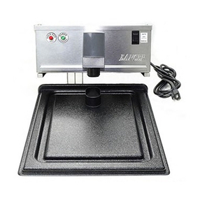
The water dispensers have the following features shown in the diagrams below:
Water Dispenser Front View Features Diagram
Water Dispenser Rear View Features Diagram
Features
REMOVABLE TOP COVER
DISPENSER HEAD
CONTROL SWITCHES
DISPENSER TOP STAND
DISPENSER LOWER CABINET
DISPENSER LOWER CABINET DOOR
REMOVABLE GRATE
REMOVABLE TOP COVER
DISPENSER HEAD
DISPENSER TOP STAND
DISPENSER LOWER CABINET
CONTROL BOX CONNECTION (inside)
DRAIN LINE HOLE
WATER SUPPLY INLET FITTING

7
Before installing your water dispenser it is important to find a
good location. Following the points listed below will provide the best
location for your water dispenser.
1. There needs to be adequate room for a customer to place a
bottle in the water dispenser for rinsing and filling.
2. Plan for electrical and plumbing requirements for the water
dispenser. The Pre-Installation Preparation section in the
Installation section of this guide explains the electrical and
plumbing requirements in detail. The most critical component of
the installation, in regards to plumbing, is the floor drain location.
A wall drain may be your only option. If a wall drain is used, be
sure there is sufficient slope to follow local plumbing codes. If a
floor or wall drain is not accessible, a pump out tank option is
available to pump water to a drain in another remote location.
3. Good lighting is required to make sure the water dispenser can
be operated properly. Lighting may be added to an installation
location easier than plumbing or floor drains.
4. An open area that can be kept clean and maintained is important
when considering the location for your water dispenser. The
installation location should not be near an overhead door.
5. The water dispenser area should be in the general traffic flow of
your store for optimum exposure.
Finding a Good Installation Location

8
Water Dispenser Unpacking Diagram
Your water dispenser has been shipped in a strapped, 2-sleeve, box. Unpack the
water dispenser by:
1. Remove the straps off the cardboard box.
2. Lift the top cardboard sleeve off of the dispenser.
3. Tip the dispenser slightly and pull out the half flaps.
4. Tip the other 3 directions to pull out the other 3 flaps.
5. Return the dispenser to the upright position with all 4 flaps outward.
6. Lift the remaining cardboard sleeve over the top of the dispenser.
Unpacking Your Water Dispenser
REMOVE TIE STRAPS

9
Your water dispenser comes fully assembled.
If you purchased the optional bottle shelving unit they will need to be installed.
Introduction
To ensure that installation of your water dispenser can be completed as quickly as
possible, it is best to have all of the electrical supplies and plumbing fittings installed before
your station arrives. All connections should be located so when your water dispenser arrives,
all you have to do is assemble it, slide it against the wall, and connect the electrical and
plumbing with a minimum amount of labour.
The water dispenser should be installed according to local electrical and plumbing
codes. If you are unable to install the station according to code, then have a plumber and
electrician complete all connections for you.
One water supply and one drain connection are required on single station water dispensers
and 2 water supply** and one drain connection are required for double dispensers.
The Water Dispenser Plumbing Diagram below shows the dimensions for the
location of all water supply and drain connections.
The Water dispenser Plumbing Diagram above shows the dimensions for the location of
the drain connections. Be sure to install according to appropriate local building codes.
NOTE: ALL DIMENSIONS ARE ACCURATE AT TIME OF PRINTING
BUT ARE SUBJECT TO CHANGE WITHOUT NOTICE.
**Note: Double dispensers should have 2 individual pure water lines connected to 2 independent pumps.
All pure water lines should be 1/2” ID min. and pumps should be 2-5 gallons per minute.
Assembly
Pre-Installation Preparation
Pure Water & Drain Connections
Installation

10
A qualified electrician must be used to complete the electrical connections for the
water dispenser. A 120 Volt, 10 Amp, power supply with 2 outlets will be required to provide
adequate electrical service for the water dispenser.
Water dispenser Electrical Connections Diagram
Electrical Connections

11
If you purchase the optional bottle and accessory shelf, please refer to picture below for
setup.
Note: Bottles and other accessory not included.
Optional Bottle Shelf Attachment & Set-Up

12
Introduction
Your new dispenser has a rinse & semi automatic fill feature. To rinse a new clean bottle, you
simply turn the bottle upside down & press the rinse button (ozone rinse). Push and hold
button, now the bottle is rinsed and ready for a fill. Turn 5&3 Gallon on bottom grate to fill. 5
gallon bottle is preset to shut off once it is filled, for the 3 gallon there is a bottle stop button
has to be pushed.
For smaller bottles the bottle shelf should be lowered to reduce the distance between the
water outlet spout and the neck opening on the bottle. To lower the shelf, simply pull ahead
on the shelf and lower it onto the shelf stopper as shown above. When your have completed
Operation
NOTE: Read all parts of the Owners Guide before
operating the Water Dispenser.
DISPENSER
(BFDSA-1 SHOWN)
1 GALLON BOTTLE SHELF
LATCHED IN UPRIGHT
POSITION
STOPPER
OZONE RINSE
FEATURE
5 & 3-GALLON
BOTTLE SHELF

13
filling your bottle and have removed it from the fill chamber, return the shelf to the storage
position.
Activation Controls
Once the bottle is full, re-apply the cap. New caps for crown neck bottles should be available
to the customer at no extra charge. Remove the bottle.
For double dispensers, two bottles may be filled at the same time.
Adjusting Bottle Fill Capacity
To adjust fill capacity auto shutoff, first remove dispenser top cover. Locate & put in place a 5
Gal bottle in dispensing compartment, start flow & time filling of the bottle to approximately
90% (Start of the neck of the bottle) as shown in bottle fill illustration. Adjust timer knob to
approximate time (each number indicates 1-minute increments). Empty & retest bottle fill &
timer, adjust to reach appropriate fill level. Once achieved, reinstall top cover. Operation of
timer function is to prevent start button being pushed & unit left to run continuously. For small
bottles, start fill & stop when desired fill level reached.

14
Initial Setting:
Range T1 & T2: Rotate small slotted screw (located beside T1 & T2) either
direction until window about shows ‘1M’ AND large dial shows ‘0-3’
Mode: Rotate small slotted screw either direction until ‘E’ shows in window
above.
Setting Bottle Fill Time: Adjust BOTH black knobs to the same setting
number. See above picture.
Semi Automatic Dispenser Timer Instructions

15
Regular Maintenance
Keeping your water dispenser clean on a daily basis is the best maintenance that you can
provide.
Wash your overfill tray with a scotchbrite type pad to keep your dispenser sparkling clean.
Note: Never use steel wool type scrubbers as they
will contaminate the stainless steel and promote rust.
Bottle grates can easily be removed and reinstalled as show in the diagram. Removal of the
bottle grate allows for easy and complete access to the overfill tray in each bottle fill chamber.
DAILY HOUSE KEEPING
Daily Refuse Removal
At least once per day, the dispenser should be checked for any refuse left by customers
inside the fill chambers.
Daily New Bottle & Accessory Restock
If your dispenser is equipped with the optional bottle and accessory racking, ensure a full
stock of water bottles and accessories are available for purchase by your customers in your
store.
Push-On Caps
Have a supply of new, clean, push on caps available for your customers.
Maintenance and Cleaning
DISPENSER
(BFDSA-1 SHOWN)
(1) TIP THE GRATE AT 45°
(2) PULL OUT THE GRATE

16
PROBLEM
CAUSE
A) No Water Flow when the
cycle activation switch is
pressed.
1. No power to water dispenser.
2. Ensure that there is sufficient purified water
available.
3. Check pump supply.
B) Solenoid Valve does not
turn off at the end of cycle.
1. Debris in solenoid valve is holding the valve
open. Remove the top off from the solenoid valve
by removing screws and check for blockage.
Remove blockage and/or flush valve with clean
water.
Contact any Precision Water Systems Service Centre to correct any
problems with your Water Dispenser that is not covered in this guide.
To locate a Service Centre in your area contact the manufacturer at:
Precision Design & Manufacturing Inc.
9024-100th Street
Westlock, Alberta, Canada
T7P 2L4
http://www.precisioncanada.com
e-mail: info@precisioncanada.com
Phone: (780) 349 4933
FAX: (780) 349 4957
Troubleshooting
Caution! Always Disconnect all power and let the water dispenser
cool down completely before completing any Troubleshooting.

17
Wiring List, BFDSA-1
SERIES 1
No.
Part# Color Ga Length From Conn. ToConn. From Location To Location
1330286 BLK/WHT 18 FULL 72" PLUG F250 #18-#22 TRANSFORMER TERMINAL BLOCK (LHTAB)
2330296 BLK 18 FULL 72" PLUG F250 #18-#22 TRANSFORMER TERMINAL BLOCK (RH TAB)
3 WHT 16 26" F250 #14-#16 PIGG#14-#16 TERMINAL BLOCK (RH TAB) RELAY A
4 BLK 16 12" F250 #14-#16 F250 #14-#16 TERMINAL BLOCK (LHTAB) STOP SWITCH COM
5 RED 16 20" F250 #14-#16 F250 #14-#16 TERMINAL BLOCK (LHTAB) RINSE SWITCH WHITE COM
6 RED 16 14 F250 #14-#16 BARE TERMINAL BLOCK (LHTAB) TIMER BASE 3
7064026 BLK 16 96" F250 #14-#16 F250 #14-#16 TERMINAL BLOCK (RH TAB) RINSE SOLENOID VALVE
8 BLU 16 8" BARE BARE TIMER BASE 6 TIMER BASE 7
9 RED 16 8" BARE BARE TIMER BASE 2 TIMER BASE 3
10 BRN 16 14" BARE PIGG#14-#16 TIMER BASE 1 HEAD SOLENOID VALVE A
11 WHT 16 14" BARE PIGG #14-#16 TIMER BASE 8 HEAD SOLENOID VALVE B
12 BLK 16 10" BARE F250 #14-#16 TIMER BASE 8 STOP SWITCH NC
13 BLU 16 12" BARE F250 #14-#16 TIMER BASE 8 START SWITCH NO
14 BLU 16 12" BARE F250 #14-#16 TIMER BASE 7 START SWITCH COM
15 ORG 16 9" PIGG#14-#16 F250 #14-#16 HEAD SOLENOID B START SWITCHLIGHT TOP TAB
16 ORG 16 9" PIGG#14-#16 F250 #14-#16 HEAD SOLENOID A START SWITCHLIGHT BOTTOMTAB
17 WHT 16 24" F250 #14-#16 F250 #14-#16 HEAD SOLENOID B RELAY 1
18 BRN 16 24" F250 #14-#16 F250 #14-#16 HEAD SOLENOID A RELAY3
19 WHT 16 3" F250 #14-#16 F250 #14-#16 RELAYA RELAY 4
20 WHT 16 3" PIGG #14-#16 F250 #14-#16 RELAY B RELAY 6
21 BRN 16 26" F250 #14-#16 PIGG #14-#16 RELAY B RINSE SWITCH WHITE NO
22 WHT 16 8" F250 #14-#16 FPIN RELAY 7 PUMP RECEPTACLE 1
23 BRN 16 22" F250 #14-#16 FPIN RELAY9 PUMP RECEPTACLE 2
24 064026 BRN 16 96" F250 #14-#16 F250 #14-#16 RINSE SWITCH WHITE NO RINSE SOLENOID VALVE
25 080377 BLK 18 FULL 72" F250 #18-#22 PLUG RINSE SWITCH BLACK COM OZONE GENERATOR
26 080377 BLK 18 FULL 72" F250 #18-#22 PLUG RINSE SWITCH BLACK NO OZONE GENERATOR
NOTES: 1. #1 & #2 WIRES ARE ATTACHED TO THE TRANSFORMER.
2. #25 & #26 WIRES ARE ATTACHED TO THE OZONE GENERATOR PLUG.
3. #7 & #24 WIRES ARE 6 CONDUCTORS CABLE, ONLY 2 ARE USED ON
TOP TO BOTTOM (RED, WHITE, GREEN & BLUE WIRES ARE NOT USED).
TOP END STRIP SHEATH 32" AND LOCK @ GROMMENT 34" WITH TIE STRAP.
BOTTOM END STRIP SHEATH 18".
Wiring List - PURELY NATURAL DOUBLE DISPENSER, BFDSA-1 PART # 330443A

18

19
SERIES 1
No.
Part# Color Ga Length From Conn. ToConn. From Location To Location
1330286 BLK/WHT 18 FULL 72" F250 #18-#22 TRANSFORMER TERMINAL BLOCK (RHTAB)
2330296 BLK 18 FULL 72" F250 #18-#22 TRANSFORMER TERMINAL BLOCK (LHTAB)
3 WHT 16 26" F250 #14-#16 PIGG#14-#16 TERMINAL BLOCK (RH TAB) RELAYA(LH)
4 BLK 16 12" F250 #14-#16 F250 #14-#16 TERMINAL BLOCK (LHTAB) STOP SWITCH COM(LH)
5 YLW 16 26" F250 #14-#16 PIGG#14-#16 TERMINAL BLOCK (RHTAB) RELAYA (RH)
6 RED 16 20" F250 #14-#16 F250 #14-#16 TERMINAL BLOCK (LH TAB) RINSE SWITCH WHITE COM(LH)
7 RED 16 10" F250 #14-#16 BARE TERMINAL BLOCK (RH TAB) TIMER BASE 3 (LH)
8 BLK 16 12" F250 #14-#16 F250 #14-#16 TERMINAL BLOCK (LHTAB) STOP SWITCH COM(RH)
9 RED 16 10" F250 #14-#16 BARE TERMINAL BLOCK (RH TAB) TIMER BASE 3 (RH)
10 GRN 16 20" F250 #14-#16 F250 #14-#16 TERMINAL BLOCK (LH TAB) RINSE SWITCH WHITE COM(RH)
11 064026 BLK 16 96" F250 #14-#16 F250 #14-#16 TERMINAL BLOCK (RHTAB) RINSE SOLENOID VALVE (LH)
12 BLU 16 8" BARE BARE TIMER BASE 6 (LH) TIMER BASE 7 (LH)
13 064026 BRN 16 96" F250 #14-#16 F250 #14-#16 TERMINAL BLOCK (RHTAB) RINSE SOLENOID VALVE (RH)
14 RED 16 8" BARE BARE TIMER BASE 2 (LH) TIMER BASE 3 (LH)
15 BLU 16 8" BARE BARE TIMER BASE 6 (RH) TIMER BASE 7 (RH)
16 BRN 16 14" BARE PIGG#14-#16 TIMER BASE 1 (LH) HEAD SOLENOID VALVE A (LH)
17 RED 16 8" BARE BARE TIMER BASE 2 (RH) TIMER BASE 3 (RH)
18 WHT 16 14" BARE PIGG#14-#16 TIMER BASE 8 (LH) HEAD SOLENOID VALVE B (LH)
19 BLU 16 14" BARE PIGG #14-#16 TIMER BASE 1 (RH) HEAD SOLENOID VALVE A(RH)
20 BLK 16 10" BARE F250 #14-#16 TIMER BASE 8 (LH) STOP SWITCH NC (LH)
21 YLW 16 14" BARE PIGG#14-#16 TIMER BASE 8 (RH) HEAD SOLENOID VALVE B (RH)
22 BLU 16 12" BARE F250 #14-#16 TIMER BASE 8 (LH) START SWITCH NO (LH)
23 BLK 16 10" BARE F250 #14-#16 TIMER BASE 8 (RH) STOP SWITCH NC (RH)
24 BLU 16 12" BARE F250 #14-#16 TIMER BASE 7 (LH) START SWITCH COM(LH)
25 BLU 16 12" BARE F250 #14-#16 TIMER BASE 8 (RH) START SWITCHNO (RH)
26 ORG 16 9" PIGG #14-#16 F250 #14-#16 HEAD SOLENOID B (LH) START SWITCH LIGHT BOTTOMTAB (LH)
27 BLU 16 12" BARE F250 #14-#16 TIMER BASE 7 (RH) START SWITCHCOM(RH)
28 ORG 16 9" PIGG #14-#16 F250 #14-#16 HEAD SOLENOID A (LH) START SWITCH LIGHT TOP TAB (LH)
29 ORG 16 9" PIGG #14-#16 F250 #14-#16 HEAD SOLENOID B (RH) START SWITCH LIGHT BOTTOMTAB (RH)
30 WHT 16 24" F250 #14-#16 F250 #14-#16 HEAD SOLENOID B (LH) RELAY1 (LH)
31 ORG 16 9" PIGG #14-#16 F250 #14-#16 HEAD SOLENOID A (RH) START SWITCH LIGHT TOP TAB (RH)
32 BRN 16 24" F250 #14-#16 F250 #14-#16 HEAD SOLENOID A(LH) RELAY3 (LH)
33 YLW 16 24" F250 #14-#16 F250 #14-#16 HEAD SOLENOID B (RH) RELAY1 (RH)
34 WHT 16 3" F250 #14-#16 F250 #14-#16 RELAY A(LH) RELAY4 (LH)
35 BLU 16 24" F250 #14-#16 F250 #14-#16 HEAD SOLENOID VALVE A(RH) RELAY 3 (RH)
36 WHT 16 3" PIGG #14-#16 F250 #14-#16 RELAY B (LH) RELAY6 (LH)
37 WHT 16 3" F250 #14-#16 F250 #14-#16 RELAY A(RH) RELAY4 (RH)
38 BRN 16 26" F250 #14-#16 PIGG#14-#16 RELAY B (LH) RINSE SWITCHWHITE NO (LH)
39 WHT 16 3" PIGG #14-#16 F250 #14-#16 RELAY B (RH) RELAY6 (RH)
40 WHT 16 8" F250 #14-#16 FPIN RELAY7 (LH) PUMP RECEPTACLE 1
41 BLU 16 26" F250 #14-#16 PIGG#14-#16 RELAY B (RH) RINSE SWITCH WHITE NO (RH)
42 BRN 16 26" F250 #14-#16 FPIN RELAY9 (LH) PUMP RECEPTACLE 2
43 BLU 16 8" F250 #14-#16 FPIN RELAY 7 (RH) PUMP RECEPTACLE 7
44 064026 BRN 16 96" F250 #14-#16 F250 #14-#16 RINSE SWITCH WHITE NO (LH) RINSE SOLENOID VALVE (LH)
45 YLW 16 8" F250 #14-#16 FPIN RELAY9 (RH) PUMP RECEPTACLE 6
46 WHT 16 24" PIGG#18-#22 F250 #18-#22 RINSE SWITCH BLACK NO (LH) RINSE SWITCH BLACK NO (RH)
47 064026 BLU 16 96" F250 #14-#16 F250 #14-#16 RINSE SWITCH WHITE NO (RH) RINSE SOLENOID VALVE (RH)
48 080377 BLK 18 FULL 72" PIGG#18-#22 PLUG RINSE SWITCH BLACK COM(LH) OZONE GENERATOR
49 080377 BLK 18 FULL 72" PIGG#18-#22 PLUG RINSE SWITCH BLACK NO (LH) OZONE GENERATOR
50 BLK 16 24" F250 #18-#22 F250 #18-#22 RINSE SWITCH BLACK COM(LH) RINSE SWITCH BLACK COM(RH)
NOTES: 1. #1 & #2 WIRES ARE ATTACHED TO THE TRANSFORMER.
2. #47 & #48 WIRES ARE ATTACHED TO THE OZONE GENERATOR PLUG.
3. #11, #13, #44 & #47 WIRES ARE 6 CONDUCTORS CABLE, ONLY 4 ARE USED
ON TOP TO BOTTOM (RED & WHITE WIRES ARE NOT USED).
TOP END STRIP SHEATH 32" AND LOCK @ GROMMENT 34" WITH TIE STRAP.
BOTTOM END STRIP SHEATH 18".
Wiring List - PURELY NATURAL DOUBLE DISPENSER, BFDSA-2 PART # 330447A
Wiring List, BFDSA-2

20
This manual suits for next models
4
Table of contents

