Precision RAVEN SMARTRAX Owner's manual

SMARTRAX SUPPLEMENT
INSTALLATION MANUAL
GVM PREDATOR
117-0190-035

DISCLAIMER
While every effort has been made to ensure the accuracy of this document, Raven
Industries assumes no responsibility for omissions and errors. Neither is any liability
assumed for damages resulting from the use of information contained herein.
Raven Industries shall not be held responsible or liable for the effects of atmospheric
conditions and sunspot activity on the performance of our products.
Raven Industries cannot guarantee the accuracy, integrity, continuity, or availability of
the GPS signal from the US Department of Defense/NAVSTAR GPS satellites, the
OmniSTAR correction service or the WAAS correction service.
Raven Industries accepts no responsibility for the use of the signal for other than the
stated purpose. Raven Industries shall not be responsible or liable for incidental or
consequential damages or a loss of anticipated benefits or profits, work stoppage or
loss or impairment of data arising out of the use or inability to use the Smartrax or any
of its components.

RAVEN INDUSTRIES
LIMITED WARRANTY
WHAT IS COVERED?
This warranty covers all defects in workmanship or materials in your Raven
Flow Control Product under normal use, maintenance, and service.
HOW LONG IS THE COVERAGE PERIOD?
This warranty coverage runs for 12 months from the purchase date of your
Raven Flow Control Product. This warranty coverage applies only to the
original owner and is not transferrable.
HOW CAN YOU GET SERVICE?
Bring the defective part, and proof of date of purchase, to your local dealer.
If your dealer agrees with the warranty claim, he will send the part, and
proof of purchase to his distributor or to Raven for final approval.
WHAT WILL RAVEN INDUSTRIES DO?
Whenourinspectionprovesthewarrantyclaim,wewill,atouroption,repair
or replace the defective part and pay for return freight.
WHAT DOES THIS WARRANTY NOT COVER?
Raven Industries will not assume any expense or liability for repairs made
outsideourplantwithout writtenconsent. Wearenotresponsiblefor damage
to any associated equipment or product and will not be liable for loss of
profit or other special damages. The obligation of this warranty is in lieu of
all other warranties, expressed or implied, and no person is authorized to
assume for us any liability. Damages caused by normal wear and tear, mis-
use, abuse, neglect, accident, or improper installation and maintenance
are not covered by this warranty.

RAVEN INDUSTRIES FLOW CONTROL DIVISION
205 East Sixth Street - P.O. Box 5107 - Sioux Falls, South Dakota 57117-5107
E-mail: [email protected]
www.ravenprecision.com
Toll-free: 800-243-5435 - Fax: 605-331-0426
Supplement Installation Manual, GVM Predator #016-0190-035 Rev A 07/04

1
TABLE OF CONTENTS
016-0190-035
07/04
MOUNTING THE UNIVERSAL BRACKET AND STEERING POSITION SENSOR ..........................2
MOUNTING THE HYDRAULIC VALVE AND PRESSURE SWITCH .................................................2
HOSE CONNECTIONS AND ROUTING ............................................................................................3
PRESSURE HOSE .................................................................................................................4
EXCESS FLOW HOSE...........................................................................................................4
TANK PORT TO ORBITAL HOSE..........................................................................................5
A-PORT TO LEFT STEER HOSE ..........................................................................................5
B-PORT TO RIGHT STEER HOSE ........................................................................................5
2
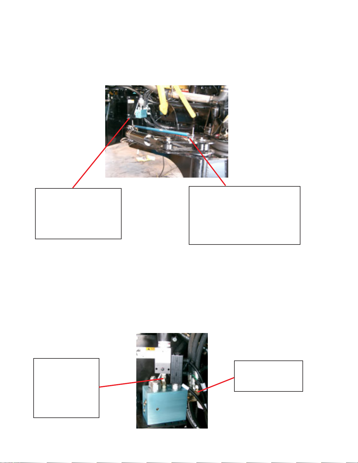
MOUNTINGTHE UNIVERSALBRACKETandSTEERING POSITIONSENSOR
Attach the universal mounting bracket on the right side of the machine using the provided 1/2” hex-
head bolts. Drill holes to fit the mounting bracket pattern and the air filter support hole pattern in a
steel plate. Figure 1 shows the bracket mounted to the machine with the valve attached and the
steering position sensor band-clamped to the right steering cylinder and the steering control arm.
FIGURE 1
MOUNTING THE HYDRAULIC VALVE and PRESSURE SWITCH
Position the hydraulic valve on the universal bracket over the top of the proper hole pattern. Secure
the valve to the bracket using the provided metric bolts and lock washers. Note: It may be neces-
sary to drill additional holes in the mounting bracket if the valve is not in an accessible posi-
tion.
Removetheelbow fitting from the pressure switch and attachthe switch to thePS-portonthe valve by
turning the solenoid connection so the switch just fits on the valve. Secure the switch by tightening
the remaining swivel fitting on the valve. (Shown in Figure 2)
Control valve is mounted
to a steel plate that must
be made to fit 3 existing
holes on the machine’s air
filter support bracket.
Steering Position Sensor mounted to
right side steering cylinder and the
control arm of the wheel. Cables for
the sensor are run along the axle
with enough extra cable to
accomadate for different axle widths.
Elbow fittings route
the hoses upward.
Pressure switch
and solenoid
connections may
need to be turned
to fit on the valve
as shown.
FIGURE 2
3
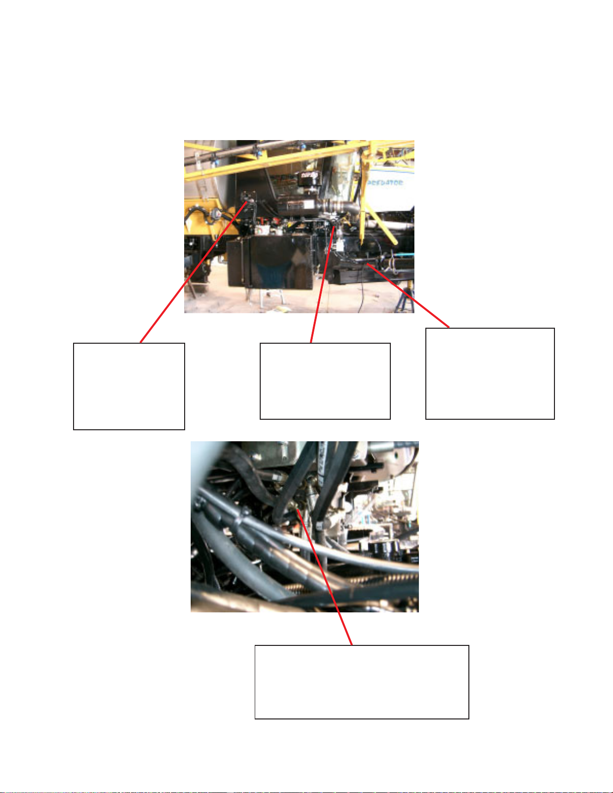
FIGURE 3
HOSE CONNECTIONS and ROUTING
New hoses should be run so they follow the approximate routing of the old hoses. This keeps crops
and debris from dragging on the hoses during operation. Run the new hoses from the valve upward
using supplied 90-degree elbow fittings and route the hoses underneath the cab toward the steering
orbital. (Shown in Figures 2, 3 and 4)
Valve control cable
is routed into the
cab through the
electrical connec-
tion bulk head.
Hoses from the valve
are run upwards from
the valve and under-
neath the cab.
Cables for the steering
position sensor are
secured to existing
hoses on the right side
of the machine.
All tees are placed on the steering orbital.
Existingtank,boom lock, rightandleftsteer-
ing lines are attached to one side of their
respective tees.
FIGURE 4

4
PRESSURE HOSE
Remove the existing pump to orbital hose and connect the provided pressure line with the 90-degree
elbow end to the pump. Route the hose along the frame underneath the cab to the P-port on the
hydraulic valve. Attach a 3/4” jic 90-degree adapter fitting to the P-port on the hydraulic valve and
connect to the Pressure hose. (Shown in Figure 5)
New pressure hose connects
to the pump using the 90o
swivel end.
FIGURE 5
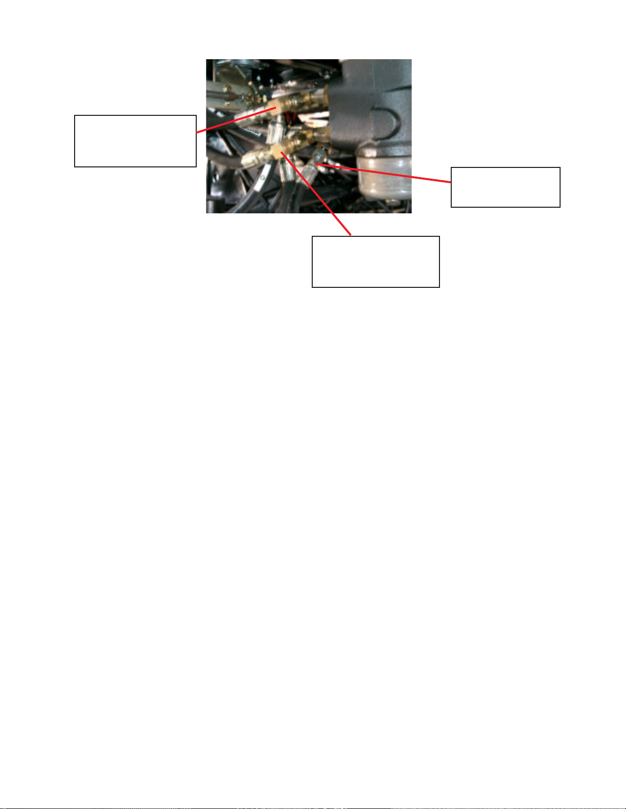
EXCESS FLOW HOSE
Attach a 90-degree elbow adapter fitting to the valve and connect the 3/4” JIC straight end of the
Excess flow hose to the hydraulic valve. Connect the 9/16” JIC straight end of the hose to the open
pressure port on the steering orbital. NOTE: The machine may have a boom lock function attached
to a tee on the pressure port of the orbital. If a tee is on the orbital, attach the Excess flow hose to the
tee, leaving the boom lock hose connected to the other side of the tee. (Shown in Figure 6)
5
Left Steer hose with
tee and elbow fitting
Boom lock hose
Right steer hose with
tee and elbow fitting
FIGURE 6
TANK PORT TO ORBITAL HOSE
Disconnect the existing line from the orbital to the tank. On the orbital, attach a tee fitting and a 9/16”
JIC fitting end of the Tank Port to Orbital hose. Re-connect the existing tank line. Attach a new Tank
Port to Orbital line to the open port on the tee fitting. On the hydraulic valve, attach a 90-degree 9/16”
JIC fitting and connect the remaining loose end of the Tank to Orbital hose to the elbow fitting.
A-PORT TO LEFT STEER HOSE
Remove the hose attached to the left steer port of the orbital. Install a 9/16” JIC tee fitting on the
orbital and re-attach the original left steer hose. On the open port of the tee fitting, attach a 90-degree
9/16” JIC elbow. Connect one end of the “A-Port to Left Steer” hose to the elbow. Attach another 90-
degree 9/16” JIC elbow to the B-Port on the Steering Control Valve. Connect the remaining loose end
of the “A-Port to Left Steer” hose to the elbow fitting. (Shown in Figure 6)
B-PORT TO RIGHT STEER HOSE
Remove the hose attached to the right steer port of the orbital. Install a 9/16” JIC tee fitting on the
orbital and re-attach the right steer hose. On the open port of the tee fitting, attach a 90-degree 9/16”
JICelbow. Connectoneend of the B-Port to Right Steerto the elbow. Attach another 90-degree 9/16”
JIC elbow to the B-Port on the Steering Control Valve. Connect the remaining loose end of the B-Port
to Right Steer hose to the elbow fitting.
NOTE: It is important to trace the hoses so that the pressure and tank hoses are not accidentally
swapped for each other. This will cause valve failure. If the Left and Right Steer hoses are swapped,
the machine will steer in opposite direction. If the machine does steer in opposite directions, the DIN
connectors on the left/right coil stack can be switched to correct the steering.
Table of contents
Popular Utility Vehicle manuals by other brands


Landoll
Landoll 330C Operator's manual

Stiga
Stiga TITAN 740 DC Instructions for use

Linhai
Linhai Landboss LH800U-2D Owner's/operator's manual

probst
probst VM-301-KJ-GREENLINE operating instructions

Thomas
Thomas PROTOUGH 900 Owner/operator and parts manual

HOMCOM
HOMCOM 341-028 Operating instructions and assembly manual


