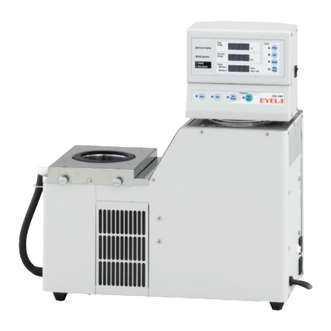
EYELA FDU-1110 User manual

Instruction Manual
Tokyo Rikakikai Co., Ltd.
FREEZE DRYER
Model FDU-1110(220V)
Model FDU-2110(220V)
R02
This manual contains important matters to maintain the functions and to use this product safely.
Keep this manual with care near the product for quick reference.
Important
Be sure to read “Safety Precautions”
carefully before use.

1. Signal Words for Warnings
This product has a certain section that may cause
unexpected injury if contacted in a way other than
specified during operation, or misused.
However, if you know such risks in advance, you
can avoid most of accidents.
Therefore, important safety information on the
matters to be noted is defined as follows and
indicated with the following alert symbols and
signal words. Be sure to follow these
instructions and use the product safely.
Alert Symbols
Signal Words Definition
WARNING Indicates a potential hazardous situation in which
mishandling will result in death or serious injury of the user.
CAUTION Indicates a potential hazardous situation in which
mishandling will result in minor or moderate injury of the user
or damage to the property.
Though we have given enough considerations to almost possible hazards during the
product use, it is still very difficult to anticipate all of the possible hazards. Therefore,
precautions described in this manual may not cover these hazard completely.
However, if you follow the instructions in this manual, you can operate the product and
perform your tasks more safely.
Be sure to use the product with special care to avoid accidents and product failure.
Safety Precautions

* If the caution label become illegible due to damage on them, replace it with the new one.
Contact us for spare labels.
2. Caution Label on the Product
The caution label that is important especially is attached to the main body of the product.
This label is located as in the figure shown below.
Follow the instruction on the label with care during the product usage.
INJURY
Do not touch
the cooling fins
with bare hands
CAUTION

Thank you very much for purchasing our product
This instruction manual describes the installation, operation, troubleshooting, maintenance and disposal
for the Freeze-dryer, Models FDU-1110 and FDU–2100.
Before using this equipment, be sure to read and understand this manual thoroughly.
5. Operation
5 - 1 Preparation for Operation
5 - 2 Operation Procedures
6. Troubleshooting
7. Maintenance/Check
7 - 1 Replacement of Consumables
7 - 2 Operation Test of Leakage Breaker
7 - 3 Replacement of Fuse
7 - 5 Cleaning and Maintenance of Product
8. Disposal of Product
1. For Safe Use of the Product
2. Description of Product
2 - 1 Application
2 - 2 Product Specifications
2 - 3 Data for Progress of Sublimation (Informative)
2 - 4 Option
2 - 5 Name of Each Part
3. Names and Functions of Operation Parts
3 - 1 Control Panel
3 - 2 Safety Function
4. Installation
4 - 1 Installation Environment
4 - 2 Installation Conditions
4 - 3 Installation Procedures
4 - 4 Connection of Utility
1
2
2
3
4
8
9
12
14
14
15
16
Trap Barrier
Air Inlet Barrier Vacuum Joint Pipe
Trap Cover
Vacuum Hose
NOTE Check attached parts inside the cold trap and main body.
Introduction
Contents
17
21
30
33
34
34
35
36
For FDU-1110 &
FDU-2110
QTY
Main Body
2
3
Manifold-Base Holder
4
5
PMH-Base Holder
1 1
1
1
1
Trap Barrier
Parts Names
6
Trap Cover
1
1Air Inlet Barrier
Fuse (3.15 A)(Spare)
1
7
8
1
Vacuum Joint Pipe
Vacuum Hose (Inner 18DIA)1
Nos.
10
7 - 4 Control of Vacuum Pump
Oil 34
Before assembling the product, check the types and quantities
of the component parts in the package.
Items in Package
Fixing
Screw
Manifold-Base Holder PMH-Base Holder
Guarantee 112
User’s Manual 111
Fixing Screw 29

For Safe Use of the Product
1
Since this product is not constructed as an explosion-proof equipment, handle the product with
special care for safety.
Never touch the cooling fins with bare hands during maintenance.
Sharp edges of the fins may hurt user’s hands.
Do not touch the cooling fins with bare hands
Be careful of vaporization of specimen such as organic solution and
others which contain flammable material.
Use extreme caution about vaporization of flammable material such as
organic solvent and others. If any solvent not trapped enters into the
vacuum pump, it can be ignited and burnt.
Cooling Fins
-1 -
Pre-freeze the container for specimen.
Never start the vacuum pump before inner walls of Cold Trap
has been cooled enough.
Install the container only when the trap has been vacuumed completely.
Replace the oil in the vacuum pump regularly.
WARNING
CAUTION

Description of Product
2
2-1 Application
2-2 Product Specifications
This product is usable for drying dilution or solution
such as protein or enzyme. Moreover, the product can be
used for drying biological specimens such as
extracted solution, urine, blood serum and others.
-2 -
Pirani Vacuum Gauge
Digital Display: 0.0 to 533.3Pa
Output of Recorder *2 Temp. on trap: 1C/1 mV Vacuum: 1 Pa/1 mV
Power Supply Input *4
Rated Power Supply AC220 V±5%, single phase, 50/60 Hz
Model No.
Refrigerating Machine
Plug Socket
Weight
Product Name
Refrigerant
Room Temperature Range
Freeze Dryer
FDU-2110
Trap Cooling Temp.
Amount of Dehumidification
Trap Ice-melting Function
Dimension of Trap (mm)
Vacuum Gauge
Ice-melting function using hot gas
Inner diameter: 200, height: 300
-80C
3 liters/each time
500 W x 2
R404A, R23
5 to 35C
700(W) x 550(D) x 930(H)
Approx. 140 kg
5.5A, 2.4 kVA
Cooling System Vessel cooling system
100 V AC, Max. 3 A
Displacement of Vacuum Pump 100/120 L/min(50/60 Hz)or more (option)
Other Functions Control of vacuum pump, display for availability of freeze dry
Indication accuracy at 0.4 to 4.0 Pa ±2.0 Pa
at 4.1 to 10.0 Pa ±3.0 Pa
at 10.1 to 15.0 Pa ±4.0 Pa
at 15.1 to 40.0 Pa ±7.0 Pa
-45C
4 liters/each time
600 W
R404A
Approx. 100 kg
7.7A, 1.7 kVA
FDU-1110
*1. The values are based on the following conditions: Room temperature at 20 °C, no load
*2. Contact Tokyo Rikakikai about the connecting-cord specified for the recorder in FDU Series with no charge.
*3. Projections are not included in outer dimensions.
*4. Capacity of plug socket is not included in the value of rated power supply input.
Do not modify the product. Use the
product for the intended purpose only.
If you modify the product or use it for
purposes other than the intended,
it may result in electric shock or equipment failure.
WARNING
Performance
Functions
Ratings Components
Outer Dimensions *3

2-3 Data for Progress of Sublimation (Informative)
Conditions
■Model FDU-1110
6 pieces of flask for specimen, which contain water of 500 cc (pre-frozen) are mounted on the trap.
And amount of sublimation is calculated backward based on remaining amount of water in flasks
along with time passage.
Input voltage: AC220 V , 50 Hz
Room temperature: 20 °C
■Model FDU-2110
8 pieces of flask for specimen, which contain water of 375 cc (pre-frozen) ) are mounted on the trap.
And amount of sublimation is calculated backward based on remaining amount of water in flasks
along with time passage.
Input voltage: AC220 V , 50 Hz
Room temperature: 20 °C
Progress of sublimation depends on conditions in use such as room temperature, capacity
and shape of specimen container (round-bottom flask or bottle), characteristic and amount of
specimen, and condition of pre-freezing..
Amount of
sublimation
(L)
10 20
1
2
3
Period(hour)
222 6 8 12 14 16 18423
0024 25
FDU-2110
Models FDU-1110 and FDU-2110
FDU-1110
-3 -

2-4 Option
■Manifold for Test Tube, Ampul, and Vial Container
■Dry Chamber
Performs freeze-drying using vial container or petri dish.
■Confining Dry Chamber
The top shelf can be confined after freeze-drying is completed.
The rest of the shelves can be used as dry chamber.
Models Code Nos.
PMH-12
PMH-24 119790
119810
Models Code Nos.
119730
DRC-1N
DRC-2L
Models Code Nos.
■Manifold for Flask
T-shaped manifold made of stainless material. 4 ports for
mounting specimen-container are provided for Model PMH-4, and
8 ports for PMH-8. Several specimens can be freeze-dried at the
same time using multiple port for specimen container.
Models Code Nos.
PMH-4
PMH-8 119820
119830
■Port for Round-bottom Flask
Round-bottom flask made of stainless material. 9 ports for
mounting specimen-container are provided for Model PMH-1000.
Inside of manifold is washable.
Models Code Nos.
PMH-1000 197440
* To use this device incorporating into
the product, remove the base legs.
-4 -
BSC-2L BSC-3L Base Leg
Base Leg
DRC-2L Base Leg DRC-3L Base Leg
PMH-4 PMH-8
PMH-24
PMH-1000
PMH-12
DRC-1N Base Leg
DRC-3L 119750
119770
BSC-2L
BSC-3L 119790
119810
T-shaped manifold made of stainless material. 12 ports for
mounting specimen-container are provided for Model PMH-12,
and 24 ports for PMH-24. Several specimens can be
freeze-dried at the same time using multiple port
for specimen container.
* Appropriate adaptors are required to use ampul and
test tube respectively.
* To use this device incorporating into
the product, remove the base legs.

■Cock B, Test Tube, Ampul, etc.
1
2 3 4
5
6
7
8
9
-5 -
Cock B
Vacuum Cock Body B
Vacuum Cock B
Specifications Code Nos.
Parts Names
Nos. 119930
144480
144490
1
2
3
Adapter for Ampul
Sealing
QTY
For 8
For 6120520
120530
145610
1
1
5
Liner B 143960
10
B-type Adapter for Test Tube 120510
143970
143980
143990
144000
Test Tube for Rim 10 x 75 (3 mL)
12 x 75 (4 mL)
12 x 90 (5 mL)
12 x 105 (6 mL)
12 x 120 (7 mL)
13 x 75 (5 mL)
13 x 90 (6 mL)
13 x 100 (7 mL)
15 x 85(8 mL)
15 x 105 (10 mL)
15 x 150 (15 mL)
16.5 x 10⁵ (12 mL)
16.5 x 165 (20 mL)
18 x 165 (24 mL)
18 x 180 (27 mL)
21 x 200 (42 mL)
144010
144020
144030
144040
144050
144060
144070
144080
144100
144110
144120
144090
100
100
100
100
100
100
100
100
100
100
50
100
50
50
50
50
1
120210
Ampul Eggplant Type(1 mL)
Pencil-type with round bottom (1 mL)
Flat Bottom (2 mL)
120220
120221
120230
120240
120250
120260
120270
120280
10
10
20
20
20
20
20
20
20
1
1
1
4
5
6
7
8
9
Pencil-type with flat bottom (1 mL)
Flat Bottom (5 mL)
Flat Bottom (10 mL)
Round Bottom (2 mL)
Round Bottom (5 mL)
Round Bottom (10 mL)

-6 -
Flask for Specimen 50 mL
100 mL
200 mL
300 mL
500 mL
1000 mL
116140
116150
116160
116170
116180
116190
1
1
1
1
1
1
Specifications Code Nos.Parts Names
Cock D
Vacuum Cock Body D
Liner A
Vacuum Cock D
Adapter for Flask
10
11
12
13
14
15
209570
233480
143950
233490
120470
144500
Nos. QTY
1
1
10
1
1
1
T 29
S
T 24
S
T 29
S
T 29
S
T 29
S
T 29
S
T 29
S
T 29
S
■Cock D, Freeze-dry Bottle, Flask, etc.
11
12
13
10
14
16 17 18
8
15
24
15
19
21
20
23
22

Specifications Code Nos.
Parts Names
Nos. 50 mL
100 mL
200 mL
300 mL
500 mL
1000 mL
116220
116230
116240
116250
116260
116270
QTY
Freeze-dry Bottle 40 mL 45
80 mL 45
120 mL 70
150 mL 70
300 mL 70
600 mL 105
900 mL 105
1200 mL 105
120050
120060
120120
120130
120140
120070
120080
120090
1
1
1
1
1
1
1
1
Freeze-dry Bottle Set 40 mL
80 mL
120 mL
150 mL
300 mL
600 mL
900 mL
1200 mL
119940
119950
119960
119970
119980
119990
120000
120010
1
1
1
1
1
1
1
1
1
1
1
1
1
1
Filter Holder 120100
Filter
Cap (for Adapter for
Freeze-dry Bottle) For 45 40/80 mL
For 70 120/150/300 mL
For 105 600/900/1200m
Adapter for Freeze-dry Bottle
120450
120460
120110
120020
120030
120040
A-type Adapter for Test Tube
16 120500
1
Multiple Serial Connection Adapter 120490
1
3
2
1
1
1
100 sheets/1 box
Flask for Specimen
17
18
19
20 1
21
22
23
24
T 24
S
T 24
S
T 24
S
T 24
S
T 24
S
T 24
S
1
-7 -
15
■Connecting Cord for the Recorder on FDU
Connecting cord specified for FDU *No charge
Model Code No.
Connecting Cord for
the Recorder on FDU 240170

-8 -
2-5 Name of Each Part
Air Inlet
Packing for Air Inlet
Air Inlet Barrier
Trap Cover
Inspection Door
on the Right
Packing for Trap
Control Panel
Ventilation Cover
Level Adjuster
Caster
Trap Barrier
Rubber Tray for Dewdrop
Fuse Holder
Plug Socket
Cold Trap
Caster
Component specified for
FDU-1110/FDU-2110
respectively
Inspection Door for Vacuum Pump
Fuse Holder
Recorder Output
(Vacuum)
Recorder Output
(Temp. in Trap)
Plug Socket
Recorder Output
(Vacuum)
Recorder Output
(Temp. in Trap)
Drain Cap
Drain Hose Fixing Parts
* Contact Tokyo Rikakikai for connecting
cord (provided with no charge) for the
recorder on FDU as necessary.
Fixing Parts
(Vibration-Proof)
Installation Female Screw
for Manifold-Base Holder

Power Switch
(Earth Leakage Breaker)
Names and Functions of Operation Parts
3
3-1 Control Panel
-9 -
Vacuum Gauge Display
Trap
Temp. ℃
Vacuum
Gauge Pa
Timer hour
Mode1
Mode2
Freeze Drying
Refrigerator
Alarm
Ref.Alarm
▼
▲Disp
Set
Reset
Run
Stop
Timer
hour.min
Trap Temp. Display
Timer Display
Freeze Drying
Ready Lamp
Refrigerator
Lamp
Alarm Lamp
Alarm Lamp
for
Refrigerator
Timer Mode Lamps
Timer Mode Select Switch
Set Key Switch
Set Key Lamp Timer Switch
DefAuto
Refrigerator
Run
Stop
Auto/Manual Select
Switch
Auto Operation
Lamp Refrigerator Switch
Refrigerator Switch Lamp
Vacuum Pump
Switch Lamp
Vacuum Pump
Switch
Vac
Pump
Defroster Switch
Defroster Switch Lamp
Trap Monitor Lamp
(AC100V only)
Timer Lamp Timer Reset
Switch
Trap Monitor
18
1
12
11
10
13
14
15
16
17 20
23
19
21
22
24
4
5
6
7
8
9
2
3

Nos. Component Names Functions
Power switch ON/OFF switch for power supply (earth leakage breaker used)
Auto Operation Lamp
Auto/Manual Select Switch
Refrigerator Switch Lamp This lamp is lighted when the Refrigerator Switch is turned ON.
Vacuum Pump Switch Lamp
Refrigerator Switch When this switch is tuned ON under Auto/Manual operation,
the refrigerator is started. In Auto operation, at the time the trap temp.
reaches –50C, vacuum pump is operated automatically.
All of the units are stopped when the switch is turned OFF.
Vacuum Pump Switch
Press this switch to switchover automatic/manual operation.
This lamp is lighted when Auto/Manual Select Switch is turned ON,
and Auto is selected.
When this switch is tuned ON under Manual operation, the power will be
supplied to the plug socket for vacuum pump. (Ref. 5-1 Preparation
for Operation) Plug the power cord of the vacuum pump into this socket.
In Auto operation, only the stoppage of the pump is feasible.
When the switch is turned OFF, Manual operation is selected.
This lamp is lighted when the vacuum pump switch is turned ON,
or the pump is started under Auto operation.
Defroster Switch
(Press for 3 min. or more for ON/OFF)
When this switch is tuned ON after the completion of freeze-drying,
cooling unit is defrosted. The vacuum pump is stopped automatically.
Defroster Switch Lamp This lamp is lighted when the Defroster Switch is turned ON.
The lamp goes off when defrosting is completed.
Trap Temp. Display Displays temperatures measured on Trap Cooling Unit.
Vacuum Display Displays Pa value of the vacuum measured on the equipment.
Timer Display Displays a time period of measurement by switching the operation mode.
Freeze Drying Ready Lamp This lamp is lighted when preset conditions of trap temperature and vacuum
are fulfilled in Auto operation, and mounting of the containers for specimen
become feasible.
Refrigerator Lamp This lamp is lighted when the refrigerator is started.
Alarm Lamp This lamp is lighted when any of vacuum failure, vacuum or
temperature sensor, or power-failure alarm is activated.
Refrigerator Alarm Lamp This lamp is lighted when the overload relay in refrigerator is activated.
Timer Mode Lamps This lamp indicates the selected mode for timer.
Mode 1: Indicates a time period for operation of vacuum pump.
Mode 2: Indicates a time period of measurement for stopwatch function
Timer Mode Select Switch This switch selects a timer display Mode1 or Mode 2.
Set Key Switch This key switch is used to enter an appropriate preset period of power
failure provided as a power-failure-reset feature (factory preset value is
5 minutes). The switch is also used for releasing the alarm lamp
and message, and termination of buzzing.
Set Key Lamp This lamp is lighted when Set Key Switch is turned ON.
-10 -
1
2
3
4
5
6
7
8
9
10
11
12
13
14
15
16
17
18
19
20

Nos. Component Names Functions
Press this switch for 5 seconds or more to reset the displayed
period for timer.
Timer Lamp
Timer Reset Switch
Timer Switch ON/OFF switch for the stopwatch feature executed by Timer Mode 2
CAUTION
*1 Press the switches for vacuum pump, refrigerator, and timer for 3 seconds or more respectively
to stop the equipment.
*2 Press the Defroster Switch for 3 seconds or more for executing ON/OFF operation.
*3 Press the Timer Reset Switch for 5 seconds or more for executing reset operation.
Trap Monitor Lamp
(AC100V only) This lamp blinks when the (optional) trap monitor sensors amount of
dehumidified liquid inside the cold trap.
(Refer to Trap Monitor in Sec. 2-4, Option)
-11 -
21
22
23
24
This lamp is lighted while the stopwatch feature executed by
Timer Mode 2 is active.

- 12 -
3-2 Safety Function
This product has the safety functions, and displays alarm messages as described in the table shown below.
When any trouble is occurred, refer to Sec. 6, “Troubleshooting” and take appropriate measures.
Safety Functions
Safety Devices Functions Causes of Activations
Earth leakage
Breaker When activated, the breaker is
turned off to cut the power supply. Electric leakage or over-current occurred
Safety Valve for
Vacuum Pump
(Leak Valve)
This valve prevents the oil contained
in the pump flows into the vacuum
system where the valve is opened,
and the system is subjected to
the air.
Activated where the operation of the pump is
interrupted by any power failure or accident
during experiment.
Activated where freeze-drying is completed, thus
Auto operation is terminated. Or defrosting is
completed.
Activated where freeze-drying is completed, and then,
the pump is stopped by manual operation.
Overload relay
in Refrigerator
High Pressure
on Refrigerator
Switch
This feature stops the refrigerator and
turns off the Defroster Switch Lamp.
Also, the power to the plug socket
is cut off.
* Once the overload relay in refrigerator is activated, cool down the refrigerator until the relay recovers.
Turn on and off the power switch to restart the refrigerator.
Recovery time for the overload relay depends on conditions in use, so that it differs 3 to 40 minutes
Ambient temperature is too high.
Refrigerator filter is clogged.
Too many specimens are mounted at once.
Refrigerator starts (operates) under overload
Fan for the refrigerator does not operate
Low power supply voltage
Fuse for
Plug Socket The fuse (rated 3.15 A) is blown
and the power to the product
is interrupted.
Self-diagnosis
feature for
Control Board
Alarm Messages Causes of Alarms
Alarm OperationsDisplays
Alarm Functions
Refrigerator
Alarm Ref.Alarm
•Trap Temp. Display blinks
measured temp. value.
Ref. Alarm Lamp is lighted, and
the buzzer is sounded for 10 sec.,
Consequently, the whole
operation will be stopped.
This switch stops refrigerator and
turns off the Defroster Switch Lamp.
Also, the power to the plug socket
is cut off.
Ambient temperature is too high.
Refrigerator filter is clogged.
Too many specimens are mounted at once.
Refrigerator starts (operates) under overload
Fan for the Refrigerator does not operate
Any device rated 3.15 A or more is connected
to the equipment.
This feature detects any abnormal
status of the control board.
Buzzer is sounded continuously
and stops the execution of control.
Failure in the temperature regulator or an abnormal
status due to noise emission is detected.
So that execution of control is stopped totally.
Ambient temperature is too high (more than 35C).
Noise affects adversely.
Holding circuit for overload
relay on refrigerator is activated.

-13 -
Alarm Messages Causes of Alarms
Alarm OperationsDisplays
Alarm Functions
Guidewire of temp. sensor
has malfunction. *1
Detection of
malfunction
in guidewire
of temp. sensor
Lit Alarm lamp is lighted, and “0000”
is indicated on the Trap Temp.
Display and the buzzer is sounded
(for 10 seconds).
Control is continued in manual
operation. In Auto operation,
the mode is switched into Manual
operation, and control is continued.
0000
Trap Temp. Display
PrEr
Vacuum Gauge Display
Lit
*1: To release an alarm message, clear the cause of alert, and then press [Set] key. The display returns to
normal indication.
*2: Turn on the power to reset the alarm.
Alarm
Alarm
Power failure
alarm
Vacuum
Error Alarm PUPm
Vacuum Gauge Display
Lit
Control Board
Error Alarm Total control is stopped, and
the buzzer is sounded continuously.
(Due to abnormal status, no
message is specified)
Automatic recovery is attempted.
Message
not specified
Alarm
Alarm
oFF
Current trap temp.
and “OFF”
are indicated in turn.
-Measured
temp.
Backup Battery
Error Alarm CPAr
Vacuum Gauge Display
Lit Alarm lamp is lighted, and “CPAr”
is indicated on Trap Temp. Display.
Then the buzzer is sounded
(for 10 seconds), and total control is
stopped.
* Elapsed time for model 1 is cleared.
* In case of power failure, total
control is stopped despite preset
period for operation recovery
time in power failure.
Alarm
Alarm of
malfunction
in guidewire
of vacuum sensor
Alarm lamp is lighted, and “PrEr”
is indicated on the vacuum gauge
display. Then the buzzer is sounded
(for 10 seconds).
Control is continued in manual
operation. In Auto operation,
the mode is switched into Manual
operation, and control is continued.
Circuit of vacuum Sensor
has malfunction. *1
Alarm lamp is lighted, and current
trap temp. and “OFF” are indicated
in turn. Then the buzzer is sounded
(for 10 seconds).
The power recovers according to
preset power-failure-recovery
settings that had been selected.
The power failed during control
,or, the power was turned off
without terminating control. *1
Alarm lamp is lighted, and “PUPm”
is indicated on the vacuum gauge
display. Then the buzzer is sounded
(for 10 seconds).
Vacuum pump is stopped solely
in Manual operation.
In Auto operation, the pump is
stopped solely, other units are
switched into manual operation,
and their control are continued.
Vacuum range of 533 Pa or more
is indicated on vacuum gauge
display once. And “Atmo”
is indicated for 30 min. or more.
*1
Backup Battery failed or runs
out
* Press [Set] key to release alarm
message. By doing this, normal
indication recovers. However,
backup function for recovery
select for power failure and
elapsed time for Model 1 do not
operate normally.
Due to noise interference or
others, abnormal status occurred
to the control Board. Automatic
recovery cannot be executed
*2

4-2. Installation Conditions
4-1. Installation Environment
30 cm
30cm
Air Inlet
Air Outlet
Model FDU-1110: Approx. 100 kg
Model FDU-2110: Approx. 140 kg
Air Inlet
(Slits)
- 14 -
Installation
4
Use extreme caution about installation
location, air-conditioning and ventilation
Since this product uses an air-cooled-type refrigerator,
heat is discharged from the air outlet. Due to this
feature, not to raise ambient temperature, provide
sufficient ventilation system for the product.
Otherwise, use the product in air-conditioned space (in
which ambient temp.: 5 to 35C) appropriately.
If ambient temperature is raised, operation efficiency
may be deteriorated, and cooling capacity may be
dropped too.
Furthermore, operation of refrigerator under hot
temperature and high pressure may result in equipment
failure.
WARNING
Keep enough space around the product
CAUTION
Be careful in carrying the heavy product
CAUTION
If the product is installed in inappropriate environment,
It may result in equipment damage in an early stage,
or, insufficient exercise of its functions
and performance.
Be careful of installation environment
CAUTION
Install this product in places such as:
●Not subject to the direct sunlight.
●Room temperature can be maintained within 5 to
35 °C.
●Well-vented, or venting is ensured.
●No flammable or ignitable substances, liquids, and
gases placed around.
●No condensation.
●Low humidity and no splash of water.
●Little dusts.
●Horizontal, stable and solid.
(Check the weight of the product during the operation.)
To keep the product’s performance, be sure
to secure the space between product and
wall or ceiling, etc. as shown in the figure on
the right.

-15 -
(1) Release the lock on the caster stopper.
Push down the lever on the caster stopper to unlock it.
Make sure that the level adjusters (2 pieces) are lifted
from the floor.
(2) Move the product to the installation location.
4-3. Installation Procedures
Caster
Caster
Rotating Part
Product is lowered
Product is lifted
Level Adjuster
Level Adjusters
* If the product is carried on uneven ground, the caster
may be damaged by excessive impact.
Lock
Unlock Stopper
Caster
(3) When the product is placed in an appropriate
location, lock the caster stopper.
(4) If the installation location has uneven level,
secure the product using level adjusters.
* Be sure to stabilize the product to a level plane,
or, place its front face higher than the rest
with the adjusters.

4-4. Connection of Utility
(1) Check the model of product, voltage of mains
supply to be connected, phase, and ampacity.
The rating of mains supply to which the
product is connected is as shown on the right.
(2) Note that no power plug is attached
to the product.
Connect the power cord to the power board
directly. Otherwise, provide the cord with the
locking plug as shown in the figure on the right.
Be sure to ground the earth conductor securely
in either case.
When connecting the power cord to
the power source, do not use split socket
or power strip.
-16 -
Connection should be made confirming
voltage, phase, capacity, type of outlet.
WARNING
Connect earthing conductor correctly.
WARNING
Do not use split socket or power strip.
WARNING
Product Model
FDU-1110
Power necessary for connection
Ampacity
10 A
Voltages
FDU-2110 AC220 V
Single phase 7 A
Power Cord
Recommended Plugs (Lock-type)
In case power plug is not attached
Wrong power connection may cause
fire or electrical shock.
To prevent electrical shock, never connect
the earthing conductor to the pipes for gas
or water.
Doing so may cause overcurrent,
and result in burnout of cables, or fire.
220 V AC
Single phase
(Catch Cap)
AC220 V
Single phase
This manual suits for next models
1
Table of contents
Other EYELA Laboratory Equipment manuals