DecalMATE MM112-003 - Operator Manual
4
SUMMARY
SUMMARY ........................................................................................................................................................ 4
1.
INTRODUCTION........................................................................................................................................ 6
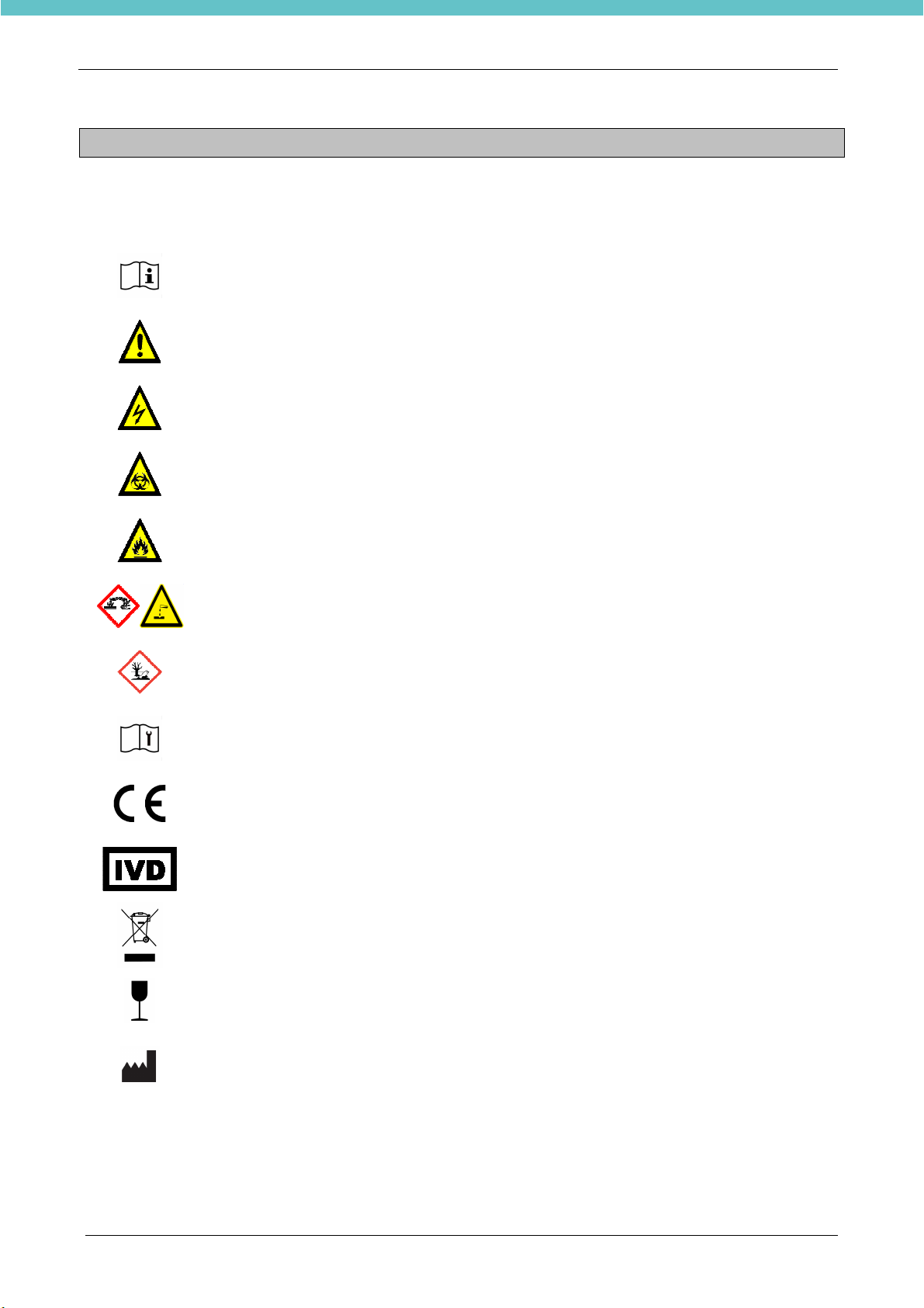
1.1.
Symbol used...................................................................................................................................... 6
1.2.
Designated uses................................................................................................................................ 7
1.3.
Technical specifications..................................................................................................................... 7
1.3.1.
Touch control terminal............................................................................................................... 8
1.4.
Transportation and storage conditions .............................................................................................. 8
1.5.
Warning information........................................................................................................................... 9
1.6.
Labelling explanation....................................................................................................................... 10
1.7.
Compatible reagents........................................................................................................................ 10
1.8.
Waste disposal of the equipment .................................................................................................... 11
1.9.
Waste disposal of reagents ............................................................................................................. 11
2.
INSTALLATION........................................................................................................................................ 12
2.1.
Space requirements......................................................................................................................... 13
2.2.
Unpacking and checking list............................................................................................................ 14
2.3.
Placement........................................................................................................................................ 16
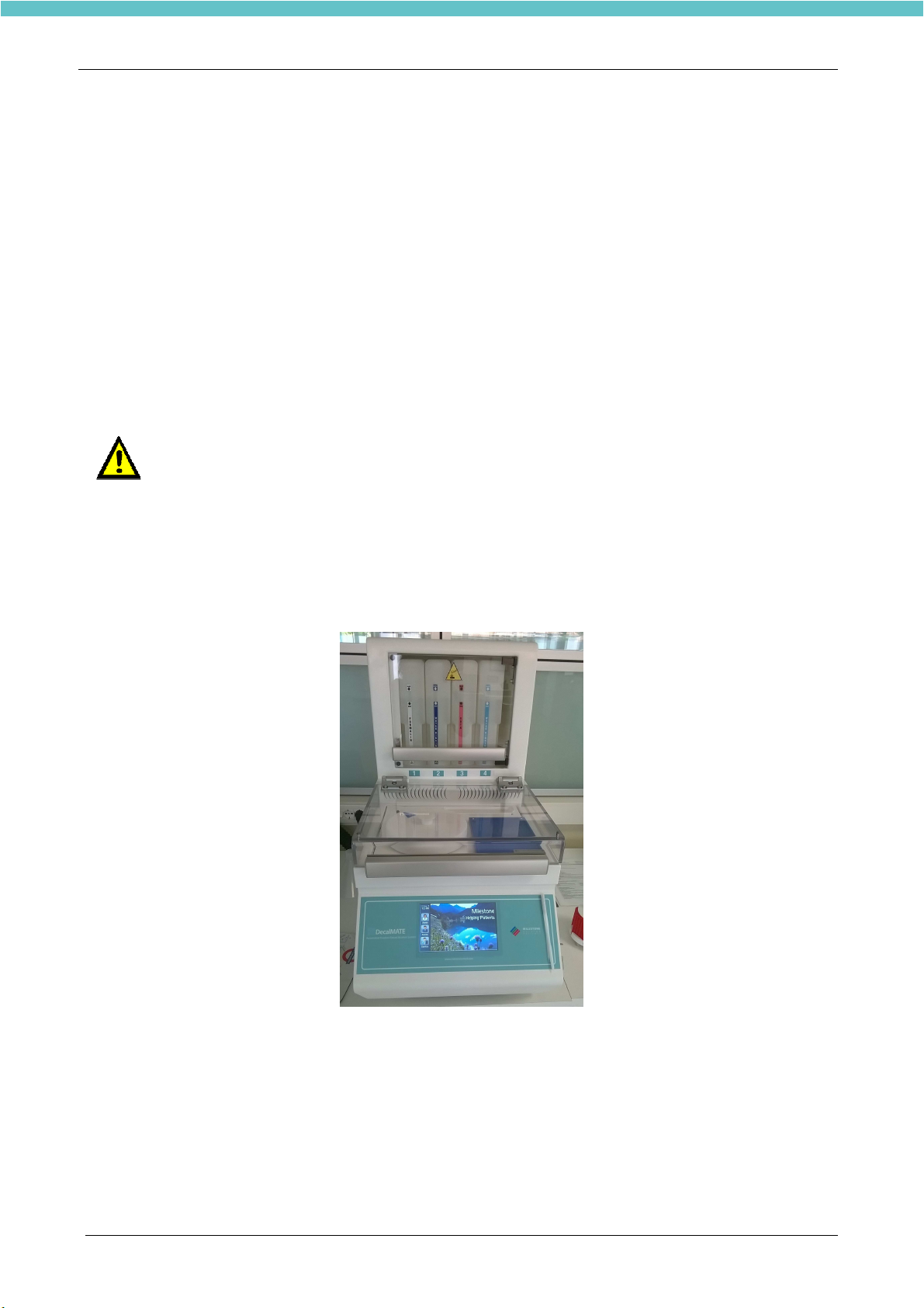
2.3.1.
Unit overview ........................................................................................................................... 16
2.4.
Fume extraction system................................................................................................................... 17
2.5.
Power supply ................................................................................................................................... 18
2.6.
Electrical installation........................................................................................................................ 18
2.6.1.
Back side connection plate...................................................................................................... 18
2.6.2.
Main power supply connection ................................................................................................ 19
2.6.3.
Power supply connection (NO UPS mode) ............................................................................. 19
2.6.4.
Power supply connection (Local UPS mode).......................................................................... 20
2.7.
Remote alarm connection................................................................................................................ 21
2.8.
Reagents.......................................................................................................................................... 22
2.9.
Log in and log out............................................................................................................................ 22
2.9.1.
Create a new user ................................................................................................................... 23
2.10.
Set system date and time................................................................................................................ 24
2.11.
Tanks............................................................................................................................................... 25
2.11.1.
Labels ...................................................................................................................................... 25
2.12.
Load DecalMATE with reagents...................................................................................................... 26
2.12.1.
Load DecalMATE with reagents.............................................................................................. 26
2.13.
Most used programs........................................................................................................................ 29
2.14.
Owner settings................................................................................................................................. 31
3.
OPERATE WITH DecalMATE.................................................................................................................. 33
3.1.
Loading cassettes into the rack....................................................................................................... 33
3.2.
Run a program................................................................................................................................. 33
3.2.1.
Run a favourite program.......................................................................................................... 34
3.2.2.
Run a standard decalcification program.................................................................................. 38
3.2.3.
Checking Status of DECAL Rate............................................................................................. 43
3.2.4.
Interval check status................................................................................................................ 45
3.2.5.
Run a program using the STEP START function.................................................................... 45
3.2.6.
Run a DELAYED PROGRAM.................................................................................................. 45
3.3.
Retrieving saved processes............................................................................................................. 46
3.3.1.
How to delete a saved process................................................................................................ 48
3.4.
Modify a program............................................................................................................................. 49
4.
REAGENTS MANAGEMENT................................................................................................................... 51
4.1.
Reagents reuse life.......................................................................................................................... 51
4.1.1.
Reagents settings.................................................................................................................... 52
4.1.2.
Recommendations for reuse life.............................................................................................. 53
4.2.
Reagents replacement procedure ................................................................................................... 54
5.
SAFETY MODE PROCEDURE................................................................................................................ 57
5.1.
Power failure.................................................................................................................................... 57
5.2.
Loading time out management........................................................................................................ 59
6.
REPORTING ............................................................................................................................................ 60
6.1.
Export processing from the terminal to the USB key....................................................................... 60
6.2.
Install and operate with the LogViewer............................................................................................ 61