manuals.online logo
Brands
  1. Home
  2. •
  3. Brands
  4. •
  5. Premier Tech Aqua
  6. •
  7. Water Filtration System
  8. •
  9. Premier Tech Aqua Ecoflo STB-570-P User manual

Premier Tech Aqua Ecoflo STB-570-P User manual

Premier Tech Aqua 1/20 Ecoflo®Polyethylene –Installation Guide Ontario
Edition: 2020-06-23
Ecoflo®Biofilter - Polyethylene
Installation Guide-Ontario
This guide contains the information required to install a Polythelyne Ecoflo®Biofilter Certified under the CAN/BNQ
3680-600 requirements. The installation must be performed by an authorized installer. A list of installers can be
provided by contacting our customer service at 1 800 632-6356.
Table of Contents
1. Technical data on the polyethylene Ecoflo®Biofilter
2. Description of system components
3. Location of components and specific instructions
4. Description of polyethylene Ecoflo®Biofilter components
5. Installation sequence
6. Storage, handling and shipping (consult the Storage, Handling and Shipping Guide on
ptzone.premiertechaqua.com)
7. Typical installations (visit ptzone.premiertechaqua.com to obtain the complete list)
1. Technical data
Component material
•Shell: polyethylene
•Cover, central support, tipping bucket, distribution plates and sampling device: polyethylene
•Filtering media: natural fiber
* See drawings on page 3.
** Weights are approximate and not binding (for handling and lifting purposes only).
models
STB-570-P/PR
Type of shell
Polyethylene
Hydraulic capacity Demand dosed option
1,755 L/d
Hydraulic capacity Time dosed option
2,195 L/d
Type of disposal
Gravity or Pumped
Type of bottom
Watertight
Length (A)*
3,380 mm (11' 1")
Width (B)*
2,000 mm (6' 7")
Height (C)*
1,850 mm (6' 1")
Inlet Height (D)*
1,260 mm (4' 2")
Inlet Height (E)*
590 mm (1' 11")
Outlet Height (Fg and Fp)*
Gravity model
38 mm (1½")
Model with integrated pump
1,240 mm (4' 1")
Weight** (including internal components and
filtering media)
Gravity model
1,190 kg (2,620 lb)
Model with integrated pump
1,200 kg (2,640 lb)
Dosing Volume
With Integrated pump : 145 L (38 US gal)
Retention Volume (between bottom of the
shell and the bottom of the filtering media)
With Integrated pump : 500 L (130 US gal)
Premier Tech Aqua 2/20 Ecoflo®Polyethylene –Installation Guide Ontario
Edition: 2020-06-23
* Weights are approximate and not binding (for handling and lifting purposes only).
2. Description of system components
2.1 Primary treatment
The primary treatment consists of a primary reactor which clarifies wastewater by letting suspended solids settle
to the bottom and retaining floating matter to avoid clogging the treatment system located downstream. An
effluent filter is installed at the outlet of the primary reactor. All primary reactors and effluent filters must comply
with local regulations.
Regardless of the septic system, opting for a primary reactor that is larger than as specified in the regulation will
contribute to improved effluent treatment performance. The Ecoflo® Biofilter can be installed with a concrete or
polyethylene primary reactor.
The effluent filter contributes to extending the useful life of any treatment system by reducing the solids in the
wastewater before it is discharged from the primary reactor. The use of an effluent filter is especially important if a
residence is equipped with a garbage disposal unit, a sewage pump or any other device that could increase the
quantity of suspended matter in the wastewater and lead to premature clogging of the treatment system. In the
case of Demand dose only, the effluent filter incorporates a flow control device.
Models
STB-730P/PR
Type of shell
Polyethylene
Hydraulic capacity Demand dosed option
2,250 L/d
Hydraulic capacity Time dosed option
2,810 L/d
Type of disposal
Gravity or Pumped
Type of bottom
Watertight
Length (A)*
4,140 mm (13' 7")
Width (B)*
2,050 mm (6' 9")
Height (C)*
1,850 mm (6' 1")
Inlet Height (D)*
1,260 mm (4' 2")
Inlet Height (E)*
580 mm (1' 11")
Outlet Height (Fg and Fp)*
Gravity Model
38 mm (1½")
Model with integrated pump
1,240 mm (4' 1")
Weight** (including internal components
and filtering media)
Gravity Model
1,405 kg (3,100 lb)
Model with integrated pump
1,415 kg (3 120 lb)
Dosing Volume
Model with integrated pump : 110 L (29 US gal)
Retention Volume (between bottom of the
shell and the bottom of the filtering media)
Model with integrated pump : 715 L (190 US gal)
Premier Tech Aqua 3/20 Ecoflo®Polyethylene –Installation Guide Ontario
Edition: 2020-06-23
2.2 Dosing tank and control unit (Time dosed biofilter only)
A dosing tank of sufficient volume must be installed downstream from the primary reactor to feed the Ecoflo
Biofilter. The dosing tank’s pump is connected to the PTA DCU-100 simplex control panel or the equivalent to
feed the Ecoflo®Biofilter 20 hours per 24-hour period. Premier Tech Aqua recommends feeding each Ecoflo®
Biofilter between 30 and 40 litres (8 and 10 US gallons) per hydraulic event.
2.3 Ecoflo®Biofilter
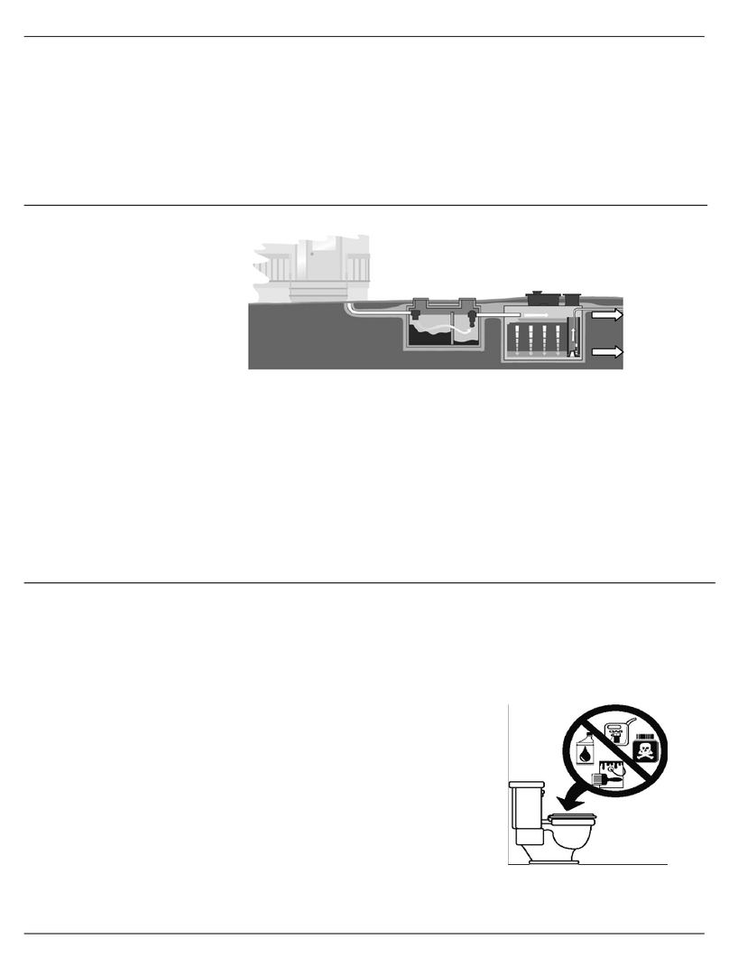
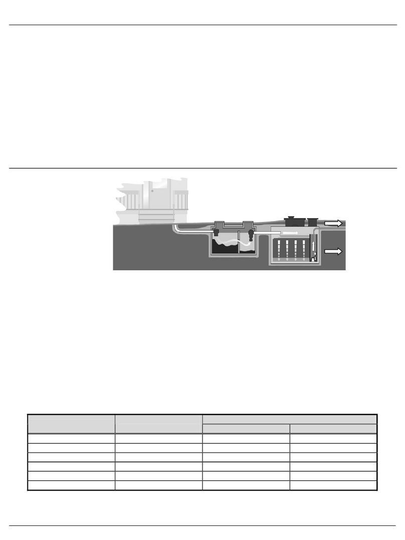
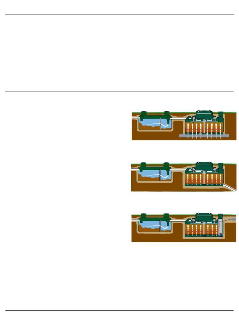
Once the primary treatment is complete, the wastewater flows from
the primary reactor to the Ecoflo®Biofilter, where it flows into a
tipping bucket that equally distributes it along the distributor plates
installed on either side of a central support. The wastewater then
trickles through a filtering media composed of natural fibers. The
organic matter contained in the wastewater is then consumed by
the microbial flora fixed onto the particles that compose the filtering
media.
Finally, the treated effluent is discharged into the environment,
either by infiltration in an absorption bed located directly under the
Ecoflo®Biofilter or release into a watercourse, provided certain
conditions are met and in accordance with local regulations.
To ensure effective treatment, there must be enough oxygen present in the system to feed the microorganisms in
the filtering media. Air enters the system through vents located on the main access cover. Depending on the
biofilter model used by the treatment system, the pumping station and/or central support allows air to circulate
between the surface and base of the filtering media. Air circulates throughout the system by way of convection
from the residence’s vent (or a standalone vent) through a feed pipe to the primary reactor.
An Ecoflo®Biofilter’s operating principle allows the system to be used continuously or intermittently without
requiring any special precautions or having any impact on the quality of the treatment. In most cases, no specific
action from the owner is required to start the system.
The Ecoflo®Biofilter model and number of units required are determined based on the number of bedrooms in the
residence or the total daily volume of domestic wastewater generated by any other type of building. It is also
determined in accordance with the surface area and existing topography and soil characteristics (nature,
permeability, depth).
There are many different Ecoflo®system models, and each model has different characteristics: type of shell used,
treatment capacity based on the number of bedrooms and presence or not of a recovery pump built into the shell.
Ecoflo Biofilter
Shell (type of)
Polyethylene
Treatment capacity
5.7 = 1,755 L/d Demand dosed or 2,195 L/d Time dosed
7.3 = 2,250 L/d Demand dosed or 2,810 L/d Time dosed
Bottom (type of)
Watertight
Discharge (type of)
Gravity or pumped
Air flow diagram
(polyethylene shell)
Premier Tech Aqua 4/20 Ecoflo®Polyethylene –Installation Guide Ontario
Edition: 2020-06-23
3. Location of components and specific instructions
3.1 Installation diagrams (demand dosed feeding)
3.2 Minimum distances to be maintained in accordance with the regulation in force
In the case of an isolated dwelling, a wastewater treatment system must be installed in a place:
•where there is no motorized traffic;
•where it is not likely to be submerged;
•that is accessible for haulage and maintenance;
•that complies with the distances in the following table:
Minimum distances to be maintained in accordance with
the regulation in force and Premier Tech Aqua specifications*
Reference point
Primary reactor
Ecoflo® Biofilter with watertight
bottom
Residence
1.5 m (5 ft.)
1.5 m (5 ft.)
Drain line
**
N/A
Property limits
1.5 m (5 ft.)
1.5 m (5 ft.)
Top of a talus
**
N/A
Water well or source
15 m (50 ft.)
15 m (50 ft.)
Tube well
15 m (50 ft.)
15 m (50 ft.)
Drinking water line
1.5 m (5 ft.)
1.5 m (5 ft.)
Swamp or pond
10 m (33 ft.)
10 m (33 ft.)
Lake or watercourse
Beyond the
shoreline limits
Beyond the
shoreline limits
Vehicle or object weighing ≥225 kg (500 lbs.)
**
4 m (13.1’)***
* The infiltration zone comprises a layer of crushed stone laid down directly under the biofilter or discharges into the environment.
** Refer to the manufacturer’s specifications.
*** Distance calculated from the cover of the Ecoflo®Biofilter.
Ecoflo®Biofilter
Pumped discharge
Primary reactor
with effluent filter
Primary reactor
with effluent filter
Ecoflo®Biofilter
Gravity discharge
Premier Tech Aqua 5/20 Ecoflo®Polyethylene –Installation Guide Ontario
Edition: 2020-06-23
3.3 Installation conditions
3.3.1 Primary reactor
The primary reactor must be installed in compliance with the following instructions:
•Both openings must be extended to the soil surface through watertight and insulated chimneys and equipped
with watertight covers;
•The depth of the backfill piled over the tank must not exceed 90 cm (36 in.);
•The installation must be 100% watertight and only receive the residence’s domestic wastewater (no
foundation, land or roof drainage);
•The primary reactor must be placed where it is not at risk of being flooded or submerged (depending on the
situation, it may be necessary to provide for drainage around the primary reactor to prevent groundwater from
reaching a level that would pose a flooding risk);
•The manufacturer’s specifications.
3.3.2 Polyethylene Ecoflo®Biofilter
The Ecoflo®Biofilter must be installed in compliance with the following recommendations and it is important to
notify all stakeholders (installer, landscaper, owner, snow removal company, etc.) of them to prevent damage to
the wastewater processing system components.
•Ensure access to the covers of your septic installation at all times. NEVER cover them with mulch, soil or a
fixed structure.
•Once your septic installation has been completed, the covers must be 50 mm (2 in.) higher than the surface of
the landscaped terrain.
•NEVER install extensions over the access of the polyethylene Ecoflo®Biofilter.
•NEVER plant trees within 2 m (6.5 ft.) of the infiltration zone.
•NEVER connect a land or foundation drainage line, gutter spout, sump or bilge pump or air conditioner drain
to your septic installation.
•NEVER pile up more than 300 mm (12 in.) of backfill on the shell.
•NEVER drive a vehicle or place objects weighing more than 225 kg (500 lbs.) within a radius of 4 m (13’ 1’’.)
from the covers of the Ecoflo® Biofilter.
•Ensure a rapid regrowth of the vegetation to prevent soil erosion.
•Ensure that the maximum seasonal groundwater level never exceeds the base of the shell.
•When dual biofilters are installed with pumped discharge, it is possible to combine a watertight-bottom
biofilter with gravity discharge and a watertight-bottom biofilter with an integrated. The base of a biofilter with
a gravity discharge must be from 25 mm (1 in.) to 75 mm (3 in.) higher than the base of a biofilter with pumped
discharge.
Also, the Ecoflo®Biofilter with a perforated bottom must be installed in a location:
•Where the soil is permeable or very permeable;
•That is never susceptible of being flooded or submerged by ground water. If that is the case, an Ecoflo
Biofilter with a watertight bottom should be used. Please contact our customer service department for further
information.
By respecting these guidelines, you contribute to the proper operation of your wastewater treatment system.
Failure to abide by these guidelines may void the warranty, at Premier Tech’s discretion
3.4 Dosing tank and control unit (Time dosed biofilter only)
The dosing tank and the control panel must be installed in compliance with the manufacturer’s specifications.
Premier Tech Aqua 6/20 Ecoflo®Polyethylene –Installation Guide Ontario
Edition: 2020-06-23
4. Polyethylene Ecoflo®Biofilter components description
Exploded view of the Polyethylene Ecoflo®Biofilter
Premier Tech Aqua 7/20 Ecoflo®Polyethylene –Installation Guide Ontario
Edition: 2020-06-23
Lids
•Access port for maintenance and inspection –main and secondary access;
•Air intake from the main lid provides proper air flow through the system;
•Secure both openings with bolted assemblies.
Insulating boards
•Thermally insulate the system;
•Guides airflow into the shell's air ducts (main access);
•Seals the system (main access).
Shell
•Encloses the system's components;
•Allows connection of water and air pipes;
•Collects the treated effluent (STB models).
Central support
•Supports the tipping bucket and one end of the distribution plates;
•Allows air circulation between bottom and top of the filtering media.
Support rails
•Support the other end of the distribution plates.
Tipping bucket
•Evenly distributes the wastewater on both sides of the filtering media;
•Creates hydraulic events required for proper distribution of the wastewater on the distribution plates and, at
the same time, contributes to the self-cleaning of the plates.
Distribution plates
•Allow even distribution of the influent on the surface of the filtering media.
Filtering media
•Consists of a natural fibre-based filtering media;
•Promotes good biomass growth which is essential to biological treatment of the wastewater;
•Physically filters the solids contained in the influent;
•Maintains adequate humidity level required for biomass viability when there is no water going through the
system for a certain amount of time.
Treated effluent collection area
•Allows proper drainage of the treated effluent;
•Allows air to circulate under the filtering media.
Pump vault / secondary access (if applicable)
•Allows air circulation between bottom and top of the filtering media;
•Allows access to the base of the system to collect a sample of the treated effluent;
•Encloses the following pumping equipment: pump, screen filter, On/Off float and alarm float (models with
integrated pump);
•Allows treated effluent to be sent towards the available disposal method (models with integrated pump).
If you have a problem, or a part is defective or missing, do not hesitate to contact
our customer service department at 1 800 632-6356.
Premier Tech Aqua 8/20 Ecoflo®Polyethylene –Installation Guide Ontario
Edition: 2020-06-23
5. Installation sequence
IMPORTANT: The installer is responsible for taking the necessary safety measures at all steps of the installation.
This includes the use of hardhats, gloves, boots, safety glasses, masks, etc.
5.1 Primary reactor
The primary reactor must be installed in compliance with the manufacturer’s specifications.
5.2 Dosing tank and control unit (Time dosed biofilter only)
Connect the primary reactor and any all other equipment to the dosing tank with pipes that meet applicable
standards. A minimum 2% downward slope must be provided to the dosing tank. The dosing tank and control
panel must always be installed in compliance with the manufacturer’s specifications. All electrical connections
must be made by a professional electrician.
5.3 Excavation, bedding and placing of the watertight bottom Ecoflo®Biofilter (STB models)
Excavate an area of approximately 3.0 m x 4.5 m (10' x 15'). Depending on soil conditions, it might be necessary
to add a layer of 150 mm (6") of either 0 to 20 mm (0 to ¾") diameter gravel void of any plant material or clean
20 mm (¾") diameter gravel surrounded by geotextile (over the excavated area). Place the shell in the center of the
excavated area. Check that the height of the installation is adequate. There are no risers available for polyethylene
Ecoflo® Biofilter models. Make sure the shell is levelled and rests on all points of the previously levelled and
compacted bed.
If you are installing a gravity discharge watertight bottom Ecoflo®Biofilter model, before going any further with the
installation, connect the effluent discharge pipe using a flexible, watertight outlet adaptor. Remove the protective
cap and punch the bulkhead of the outlet adapter. No debris resulting from that operation must be left in the
Ecoflo®Biofilter.
Connect the pipe to the Ecoflo®Biofilter. The pipe must have a constant downward slope until it reaches the
disposal area. The soil under the pipes must be properly compacted.
5.4 Extension pipe and membrane installation (STB models)
To ensure a maximum of stability, install the six (6) pipe extensions on the
existing pipes assembled on the shell. Lay the membrane on the extension
pipes on both sides of the shell. Spread and level the fill material over and under
the membranes.
Protective cap
Bulkhead to be removed
Premier Tech Aqua 9/20 Ecoflo®Polyethylene –Installation Guide Ontario
Edition: 2020-06-23
EFFLUENT PIPE
pumped discharge
EFFLUENT PIPE
gravity discharge
INLET PIPE
200 mm (8")
5.5 Initial backfill of the shell
Place backfill material around the shell up to
200 mm (8") underneath the invert of the inlet pipe.
Start with the long sides and finish with the short
sides. The backfill material must be placed with
care and not dumped (do not compact with
bulldozer).
The backfill material must be sandy, with no rocks
or stones.
CAUTION: Make sure the backfill material stays out of the shell during the backfill operation.
5.6 On site assembly
•Unscrew and remove the protective shipping material found on the main and
secondary access.
•Remove the main and the secondary access. The main access assembly includes the lid and the insulating
board. To remove the lid, unscrew the four lag screws in the four corners of the lid.
•Glue in place the elbow assembly on the water inlet pipe. Align marks to ensure that the elbow assembly is
correctly positioned. Once in place the inlet pipe must be centered with the tipping bucket. The elbow
assembly is packaged in the components box. This box is shipped with the biofilter and is located in the main
access.
CAUTION: Do not reverse the elbow. The water inlet would then be off center.
Secondary
access
Lid
Insulating board
Main access
Premier Tech Aqua 10/20 Ecoflo®Polyethylene –Installation Guide Ontario
Edition: 2020-06-23
•Attach the tipping bucket to the central support by inserting the two (2) locking catches into the central
support’s anchor slots. Bring down the opposite end to make sure the tipping bucket stays in place. Check the
state of the tipping bucket by moving it from left to right to make sure nothing is blocking its movement.
•Make sure that:
-The distribution plates are properly installed;
-The float tree and the pump are correctly positioned (models with integrated pump);
-The tipping bucket tilts correctly on both sides.
•Screw in the pump outlet adapters (models with integrated pump). These adapters can be found in the
components box (shipped within the main access of the biofilter). For the outlet, there are available two
adapters in the box of 1” and 1½”.
•Screw in place the main and the secondary access with the supplied lag screws and place the insulating
boards and lids. Secure the lid of the main access with the four lag screws and the lid of the secondary
access with the two quarter turns. The secondary access lid and insulating board are packaged in the
components box (shipped within the main access of the biofilter).
Outlet adapter
Tank adapter
Outlet pump
pipe
Locking catch
Anchor slots
Premier Tech Aqua 11/20 Ecoflo®Polyethylene –Installation Guide Ontario
Edition: 2020-06-23
5.7 Connecting the water inlet pipe (demand dose configuration)
•Connect the supply line from the septic tank to the water intake of the
Ecoflo®Biofilter, making sure that the entire length of the pipe is on a
constant downwards slope that slants towards the Ecoflo®Biofilter. Note
that the soil under the pipe must be properly compacted. The Ecoflo®
Biofilter is equipped with a standard flexible intake adaptor. Use a regular
pipe clamp to make the connection. Remove the protective cap before
connecting the inlet pipe. Do not discard the documents wrapped under
the cap: they must be handed over to the owner.
5.7.1 Connecting the water supply pipe when a pumping station is required to feed the Ecoflo®Biofilter (Time
dosing configuration)
When a pumping station is required upstream of an Ecoflo® Biofilter, the following instructions must be taken into
account:
•When a pumping station is required Premier Tech Aqua recommends sending approximately 30 to 40 L (8 to 10
US gallons) of wastewater to the Ecoflo® Biofilter every pump dosing cycle (10 tipping bucket events);
•The pumping station must be watertight (infiltration and exfiltration);
•The water supply pipe (flexible 38 mm (1½") Ø pipe) is connected to an inlet adapter which allows the
connection to the Ecoflo®Biofilter’s 100 mm (4") Ø inlet pipe. Note that the adapter is mandatory to break the
stream of water coming from the pumping station;
•An air duct must connect the pumping station to the Ecoflo®Biofilter to ensure air circulation. This air duct is
connected to the adapter, which is equipped with a tee-Y;
•Depending on site conditions, a forced air vent may be required;
•The pumping station must be accessible at all times.
When an installation consists either of two Ecoflo®Biofilters which cannot be fed by gravity or of three Ecoflo®
Biofilters, a pumping station combined with a pressurized flow divider is required. Premier Tech Aqua offers
several pressurized flow dividers. For more information on Premier Tech Aqua’s pressurized flow divider, consult
the Peripherals Section at ptzone.premiertechqua.com.
Primary
Tank
Inlet adapter
Dosing tank
Air circulation pipe
Ecoflo®Biofilter
Water supply line
Premier Tech Aqua 12/20 Ecoflo®Polyethylene –Installation Guide Ontario
Edition: 2020-06-23
5.8 Connecting the pumped discharge (models with integrated pump)
The effluent pipe from the integrated pump model must be connected to the treated effluent
disposal method (absorption disposal, watercourse, etc.) using a flexible Ø 25 mm or 38 mm (1" or
1½") pipe. This pipe must be capable to withstand a minimal pressure of 700 kPa (100 PSI) and
must also be compatible with underground applications. Now, there are two barbed Ø 25 mm (1")
and Ø 38 mm couplings (Item A) links this flexible pipe to the biofilter’s outlet (to choose the one
which better adapts to your needs). If necessary, the other end of the pipe is connected to the
pipes of the treated effluent disposal method via the coupling supplied for this purpose (Item B).
Precautionary measures against freezing must be taken if the effluent is discharged into a
watercourse. All the items can be found in the components box (shipped within the main access of the biofilter).
What you should know if you use PTA’s integrated pump:
•The maximum length of the pressurized pipe (flexible pipe) from the pump's outlet, using a 25 mm (1") Ø pipe,
depends on the head (difference in elevation between the base of the pump and the end of the pressurized
pipe). The maximum length of the pressurized pipe (flexible pipe) from the pump's outlet, using a 38 mm (1½")
Ø pipe, is limited by the volume of water that returns to the Ecoflo®Biofilter once the pump has stopped
running. The following table presents the different allowable pipe lengths:
Head (height)
7,5 m (25')
6 m (20')
4,5 m (15')
3 m (10')
1,5 m (5')
Maximum length of the Ø 25 mm (1") pipe
---
18 m (60')
21 m (70')
24 m (80')
27 m (90')
Maximum length of the Ø 38 mm (1½") pipe
30 m (100')
30 m (100')
30 m (100')
30 m (100')
30 m (100')
NOTE: The pipes must be installed in a way that they can drain properly.
WARNING: When there is a possibility of surface water accumulating on the lot, a drain pipe must be installed to
evacuate the excess water and prevent any risk of infiltration.
5.9 Final backfill of the shell
Complete the backfill. The backfill material must be
placed with care and not dumped (do not compact with
bulldozer). The backfill material must be sandy with little
or no rocks or stones. Allow space for ground cover and
make sure the lids are at least 50 mm (2") above the
surface of the landscaped lot.
Before the final backfill of the model with integrated
pump, do not forget the electrical wiring (consult next
section of the guide).
B
A
Hauteur
Length
Height
EFFLUENT PIPE
pumped discharge
EFFLUENT PIPE
gravity discharge
INLET PIPE
Maximal
groundwater
level allowed
300 mm (12")
50 mm (2")
Premier Tech Aqua 13/20 Ecoflo®Polyethylene –Installation Guide Ontario
Edition: 2020-06-23
5.10 Pump verification and electrical wiring (models with integrated pump)
Step 1 Pump verification
Make sure there is no debris (sand, stone, gravel, tie-wrap, electrical components, tape, etc.) in
the access well when the electrical wiring is complete. Visually inspect the components inside
the access well (float tree, floats, pump) to make sure they are properly installed and will work as
they should.
Step 2 Electrical wiring
The electrical wiring should be executed by an electrician. To wire the system to the residence,
two (2) in-ground double strand supply cables are required. It is preferable to protect the wires
with the appropriate piping before burying them. The wire rating must also be done by an
electrician. One of the wires will be used for the power supply line while the other one will send
the alarm float signal to the alarm box (Item C) or control panel (when required).
Waterproof electrical connectors (Item E) must be used to go through the secondary access.
IF YOUR LOCAL ELECTRIC CODE ALLOWS IT make the appropriate electrical connections using the supplied
parts (junction box (Item D), waterproof screw-thread wire connectors and electrical connectors (Item E)) located
in the components box. First, remove the connector plugs from the float and pump wires by cutting 5 cm (2") from
the end. Make 2 holes of 2 cm (13/16") in diameter in one side of the secondary access well to pass the
connectors through to the other side. Insert the wiring into the system through the 2 holes. The junction box is
located in the secondary access on the insulating board. Identify and insert the wires into the junction box as
shown in the diagram above. Use waterproof screw-thread wire connectors for the connections to ensure the
water does not affect the electrical circuit. Follow the diagram's colour code. Since the white wire of the On/Off
float is connected to the pump's black wire (live wire), wrapping the white wire in electrical tape is strongly
recommended. Close the junction box. Pass the electrical wires from the pumping unit through the groove in the
insulating board. Place the insulating board inside the access, install the junction box on top and close the lid of
the secondary access.
NOTE: Use two (2) separate circuit-breakers, one for the electrical power of the pump and the other for the alarm
box connection. Do not connect anything else on these circuit-breakers (for example: household appliance).
They must be used for the pump and the alarm box only.
The pumping unit uses 0.25 kWh per day.
Electrical
connectors
Secondary access
Junction box
Insulating board
Effluent pipe
C
D
E
Premier Tech Aqua 14/20 Ecoflo®Polyethylene –Installation Guide Ontario
Edition: 2020-06-23
Performance curve
Flow rate (L/min)
(US gpm)
Totoal head (m)
Total head (ft)
The figure on the right represents the
performance curve of the pump supplied
with the Ecoflo®Biofilter with integrated
pump. Note that this curve was obtained
with clear water, the pump might not
perform as well with wastewater. If you
have questions about the interpretation
of this curve, please do not hesitate to
contact Premier Tech Aqua.
Pump characteristics:
•0.4 HP
•6.6 Amps
•1 phase, 60 Hz, 115 V
5.11 System operation verification and warranty seals
The installed system is certified under CAN/BNQ 3680-600 (2009) and correspond to a B-IV treatment class.
After making sure the tipping bucket is fully operational and that the distribution plates are installed properly,
install the insulating board inside the main access. Seal it shut by attaching the handle of the insulating board to
the access of the Ecoflo® Biofilter using the two plastic fasteners. Finally, close the lid of the Ecoflo® Biofilter.
Note that the owner does not have to do anything in particular to start the system.
Do not forget the inspection permit, where applicable.
Premier Tech Aqua 15/20 Ecoflo®Polyethylene –Installation Guide Ontario
Edition: 2020-06-23
CHECK POINTS FOLLOWING INSTALLATION:
❑NEVER cover or bury the lids of your septic system with mulch, soil or a permanent structure. Always keep
the lids accessible.
❑The lids of you septic system must be at least 50 mm (2") above the surface of the landscaped lot.
❑NEVER install a riser on the access of a polyethylene Ecoflo®Biofilter.
❑NEVER plant a tree within 6 m (20') of the Ecoflo®Biofilter lid and within 2 m (6.5') of the absorption bed.
❑NEVER open the lids or go inside the septic tank or biofilter.
❑NEVER connect a drain pipe, roof gutter, sump pump or air conditioning drain to your septic system.
❑NEVER operate a vehicle or place objects weighing over 225 kg (500 lbs) within 4 m (13’.1’') of the lid. Pass
on this information to all those who have access to your system (landscaper, snow blower, etc.).
❑NEVER let anything accumulate on top of your septic system (for example: compacted snow). The overload
could damage the system.
❑NEVER empty the backwash of a spa or pool into your septic system.
❑NEVER empty wastewater of a recreational vehicle (camping trailer, caravan, etc.) into your septic system.
❑NEVER use automatic toilet cleaners.
❑If there is a delay in finishing the landscape after the initial installation of the system, place reference posts
and protective fences to identify the location of the Ecoflo®Biofilter. This will prevent any circulation on the
unit and help indicate the system's final level.
❑If a pumping station is installed upstream of the Ecoflo®Biofilter, an airflow duct must be connected from
the pumping station to the Ecoflo®Biofilter.
❑Households must be equipped with an air vent that is in proper working condition and complies with the
applicable standards. Premier Tech Aqua strongly recommends using a 100 mm (4") Ø pipe.
❑Hand over the package containing the Owner's Manual and the Maintenance Agreement to the customer.
This package is located inside the water intake protective cap.
❑Remind the customer to fill out and sign the Maintenance Agreement. The customer must keep the white
copy, give the yellow copy to the local regulatory body and send the pink copy to Premier Tech Aqua.
By respecting these guidelines, you are contributing to the proper operation of your wastewater treatment
system. Failure to abide by these guidelines may, at Premier Tech Aqua's discretion, render the warranty invalid.
If you have any problems, questions or comments, do not hesitate
to contact Premier Tech Aqua at 1 800 632-6356.
Premier Tech Aqua 16/20 Ecoflo®Polyethylene –Installation Guide Ontario
Edition: 2020-06-23
6. Shipping and Handling
6.1 Shipping Polyethylene Ecoflo®Biofilters from the manufacturer to the distributor
The load may vary depending on the type of trailer used. However, in order to maximize transportation, use a 53 ft
drop-deck type trailer. The following image represents an example of the 570 series mounted on a drop-deck.
3,18 m (10’ 5”) 3,92 m (12’ 10”) 4,2 m (13’ 9”)
12,8 m
(42’)
3,35 m
(11’)
11’
(3.35 m)
42’
(12.8 m)
10’ 5” (3.18 m) 12’ 10” (3.92 m) 13’ 9” (4.2 m)
Length of 2 different Ecoflo®Polyethylene models and a low bed trailer
Typical configuration for 570 models
12' 8" (3.85 m)
11' (3.38 m)
11'
(3.38 m)
42'
(12.8 m)
13' 7" (4.13 m)
Premier Tech Aqua 17/20 Ecoflo®Polyethylene –Installation Guide Ontario
Edition: 2020-06-23
Typical configuration for 730 models
•Use two (2) straps per system or group of two (2) superposed systems.
•Use three (3) straps per system or group of two (2) superposed systems for the biofilters installed at
the rear end of the trailer.
•Always position the straps according to the illustrations below.
•The systems must rest on a flat surface, free of any debris that can puncture or damage them.
•The carrier is responsible for complying with all laws and codes in effect.
•The carrier is responsible for any damage caused to the system occurring during shipment.
6.2 Shipping Polyethylene Ecoflo®Biofilters from the distributor to the installation site
•Use a trailer or vehicle with adequate loading space depending on the dimensions of the system.
•Use appropriate straps to support the systems properly and securely.
•The systems must rest on a flat surface, free of any debris that can puncture or damage them.
•The carrier is responsible for complying with all laws and codes in effect.
•The carrier is responsible for any damage caused to the system occurring during shipment.
6.3 Handling
6.3.1. Standard handling method
•Lifting rings should always be used unless a significant amount of water has infiltrated the system. In this
case, refer to Section 3.2:
Handling systems in which water has infiltrated.
Premier Tech Aqua 18/20 Ecoflo®Polyethylene –Installation Guide Ontario
Edition: 2020-06-23
•Lifting rings should always be used with lifting straps or shackles of appropriate size and capacity.
6.4 Handling systems in which water has infiltrated
If water has infiltrated the system during storage, it must be pumped out (refer to Section 5:
Pumping Procedure
).
Lifting chains must be properly secured on the protruding galvanized pipes.
•Make sure the chains or lifting straps used to move the system are strong enough to withstand the water’s
additional weight. Even if the excess water is emptied from the shell, water absorbed by the filtering media still
remains, please handle with care.
•Use equipment with adequate lifting capacity to handle the system. As specified above, the actual weight to
be handled and the dry weight indicated on the first page of this document may differ significantly due to the
amount of water in the system.
For both handling methods
•Always support the system with four (4) lifting points. Make sure the load is evenly distributed on the four (4)
lifting points (lifting rings, galvanized pipes, etc).
•When handling the system, always keep it levelled to avoid movement of the components inside the shell.
•Carefully move the system making sure everyone keeps a safe distance from the system as well as the
equipment on site.
•Handle the system gently and uniformly, sudden movements should be avoided.
•The handler is responsible for any damage caused to the system occurring while handling.
•Never handle more than one system at a time.
Premier Tech Aqua 19/20 Ecoflo®Polyethylene –Installation Guide Ontario
Edition: 2020-06-23
7. Typical Installations
The type of installation varies according to the conditions encountered in the field. Here are different types of
installations:
Type 1 –Flat site with gravity discharche
Demand dosed : Gravity feeding of the Ecoflo®
Time dosed : On demand feeding of the Ecoflo®
Primary reactor
with effluent filter
Ecoflo® Biofilter
Dosing
tank
According to
local regulation
According to
local regulation
Primary reactor
with effluent filter
Ecoflo® Biofilter
Premier Tech Aqua 20/20 Ecoflo®Polyethylene –Installation Guide Ontario
Edition: 2020-06-23
Type 2 : Flat site with pumped discharche
Demand dosed : Gravity feeding of the Ecoflo®
Time dosed : On demand feeding of the Ecoflo
If you have any questions or comments, do not hesitate to
contact Premier Tech Aqua at 1 800 632-6356.
Ecoflo® Biofilter
Ecoflo®Biofilter
Dosing
tank
Primary reactor
with effluent filter
Primary reactor
with effluent filter
According to
local regulation
According to
local regulation
The information contained in this document is based upon the latest information available at the time of publication and is
designed to provide you with a general introduction to our products. We make no warranties or representations as to its accuracy.
We are continually updating and improving our products and reserve the right to amend, add or change technical specifications
and prices for these products without prior notice. Ecoflo®is a trademark of Premier Tech Ltd. The Ecoflo®Biofilter is protected
under patents: CA2499637; US7097768; ES2285173; EP1539325 (in BE, FR). Notice issued on 2019-01-11. For up-to-date
information on patent applications and patents on this product or any portion thereof, please see our website:
patentmarking.premiertech.com (reference: 3685).
© Premier Tech Ltd., 2019

This manual suits for next models

1

Other Premier Tech Aqua Water Filtration System manuals

Premier Tech Aqua Ecoflo STB-650B User manual

Premier Tech Aqua

Premier Tech Aqua Ecoflo STB-650B User manual

Premier Tech Aqua Rewatec Fl-1 User manual

Premier Tech Aqua

Premier Tech Aqua Rewatec Fl-1 User manual

Premier Tech Aqua Conder CNSB Instruction sheet

Premier Tech Aqua

Premier Tech Aqua Conder CNSB Instruction sheet

Premier Tech Aqua Ecoflo STB-500B User manual

Premier Tech Aqua

Premier Tech Aqua Ecoflo STB-500B User manual

Premier Tech Aqua Ecoflo ST-500 User manual

Premier Tech Aqua

Premier Tech Aqua Ecoflo ST-500 User manual

Premier Tech Aqua Rewatec McRain Plus User manual

Premier Tech Aqua

Premier Tech Aqua Rewatec McRain Plus User manual

Premier Tech Aqua Prefilter Maxi Plus Installation instructions manual

Premier Tech Aqua

Premier Tech Aqua Prefilter Maxi Plus Installation instructions manual

Premier Tech Aqua Ecoflo ST-570P User manual

Premier Tech Aqua

Premier Tech Aqua Ecoflo ST-570P User manual

Premier Tech Aqua Ecoflo ST-500 User manual

Premier Tech Aqua

Premier Tech Aqua Ecoflo ST-500 User manual

Premier Tech Aqua Ecoflo Coco EC5 Series User manual

Premier Tech Aqua

Premier Tech Aqua Ecoflo Coco EC5 Series User manual

Premier Tech Aqua Ecoflo STB-570PR-DiUV User manual

Premier Tech Aqua

Premier Tech Aqua Ecoflo STB-570PR-DiUV User manual

Premier Tech Aqua Ecoflo STB-570PR-DiUV User manual

Premier Tech Aqua

Premier Tech Aqua Ecoflo STB-570PR-DiUV User manual

Premier Tech Aqua Ecoflo ST-500 User manual

Premier Tech Aqua

Premier Tech Aqua Ecoflo ST-500 User manual

Popular Water Filtration System manuals by other brands

Brita Maxtra+ Instructions for use

Brita

Brita Maxtra+ Instructions for use

Vetus FTR470 installation instructions

Vetus

Vetus FTR470 installation instructions

Austin Springs AS-WH installation instructions

Austin Springs

Austin Springs AS-WH installation instructions

Sola HD STFE Elite Series instruction manual

Sola HD

Sola HD STFE Elite Series instruction manual

Alhafidh WPHA-RO1006US6 user manual

Alhafidh

Alhafidh WPHA-RO1006US6 user manual

Astronics Trig-Tek 203M user manual

Astronics

Astronics Trig-Tek 203M user manual

SMC Networks AMD50 Series Operation manual

SMC Networks

SMC Networks AMD50 Series Operation manual

A.O. Smith Puritee+ Hot user guide

A.O. Smith

A.O. Smith Puritee+ Hot user guide

Ingersoll-Rand ARO 651412-X Operator's manual

Ingersoll-Rand

Ingersoll-Rand ARO 651412-X Operator's manual

Vestergaard LifeStraw PEAK Series user manual

Vestergaard

Vestergaard LifeStraw PEAK Series user manual

SpectraPure MPRO RO System Installation and operating manual

SpectraPure

SpectraPure MPRO RO System Installation and operating manual

KENT MAXX Instruction handbook for installation, operation and maintenance

KENT

KENT MAXX Instruction handbook for installation, operation and maintenance

Kinetico Pacifica manual

Kinetico

Kinetico Pacifica manual

Chandler Systems DROP installation manual

Chandler Systems

Chandler Systems DROP installation manual

KENT Grand Plus Instruction handbook

KENT

KENT Grand Plus Instruction handbook

Gardena FFP 5000 UVC operating instructions

Gardena

Gardena FFP 5000 UVC operating instructions

Watts Premier WP-4 BVC Installation, operation and maintanance manual

Watts Premier

Watts Premier WP-4 BVC Installation, operation and maintanance manual

ACO Grease Capture Installation and maintenance manual

ACO

ACO Grease Capture Installation and maintenance manual

manuals.online logo
manuals.online logoBrands
  • About & Mission
  • Contact us
  • Privacy Policy
  • Terms and Conditions

Copyright 2025 Manuals.Online. All Rights Reserved.