manuals.online logo
Brands
  1. Home
  2. •
  3. Brands
  4. •
  5. Kinetico
  6. •
  7. Water Filtration System
  8. •
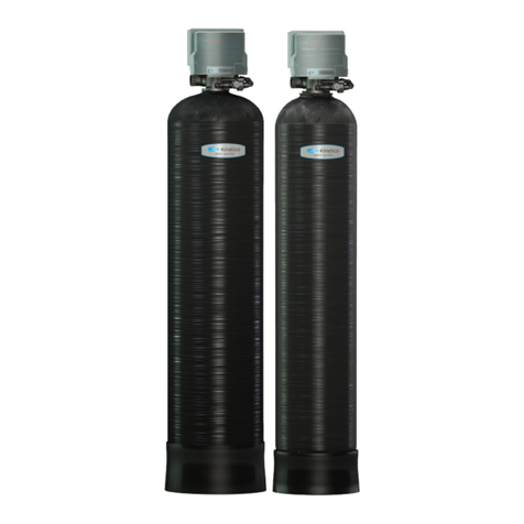
  9. Kinetico Pacifica User manual

Kinetico Pacifica User manual

1
MANUAL
EQUIPMENT
REVERSE OSMOSIS
ADVANCED REVERSE
OSMOSIS SYSTEM
DIRECT FLOW
ÍNDICE P
1
2
3
4
User manual
Technical manual
Sanitization manual
Data sheet
4
8
14
19
ADVANCED REVERSE
OSMOSIS SYSTEM
DIRECT FLOW
User manual
0. MAIN FEATURES
CLICK
QUICK CONNECTIONS
AND MAXIMUM SECURITY
FILTER CONTROL
AUTOMATIC WARNING
OF MAINTENANCE
DOUBLE
FLOW
HIGHER FLOW
OF WATER DISPENSED
SOLENOID
VALVE
IMMEDIATE CONTROL
SECURITY MESH
DIRECT
ACCESS
EASE OF ACCESS
AND MAINTENANCE
AQUASTOP
AUTOMATIC SYSTEM
LEAK DETECTION
QUALITY
CONTROL
CONDUCTIVITY
CONTROL
DIRECT
FLOW
PRODUCTION DIRECT
OSMOTIC WATER
LED
STATUS
STATUS
INDICATIONS
SOUND
WARNINGS
OUND
WARNINGS
HIGH PERFORMANCE
MOTOR
HIGH PERFORMANCE
MOTOR
PRESSURE
CONTROL
PROTECTION AGAINST
PRESSURE LOSS
HIGH
EFFICIENCY
RECOVERY
IN THE PRODUCTION
EXCLUSIVE
MEMBRANE
ORIGINAL
MEMBRANE
Keep this manual, which includes the service
book and warranty sections, in order to
provide you with better after-sales service.
USER MANUAL
FOR REVERSE OSMOSIS EQUIPMENT
ELECTRONIC
ADAPTER
GREATER SECURITY
AND EFFICIENCY
BLOCKING
FOR SECURITY
TO GUARANTEE
WATER QUALITY
5
1. INTRODUCTION
Congratulations. You have purchased an excellent piece
of equipment for domestic water treatment.
This unit will help you improve the features of your
water.
2. WHAT IS OSMOSIS?
Natural or direct osmosis is the most common in natu-
re, since semi-permeable membranes are part of the
vast majority of organisms (for example, plant roots, or-
gans of our own body, cell membranes, etc...)
When two solutions of different concentration of salts
are separated by a semi-permeable membrane, a flow
of water naturally occurs. Water from the solution of
lower concentration to the solution of higher concen-
tration. This flow continues until the concentrations on
both sides of the membrane are equal.
When it comes to investing this process and achieve a
flow of water with a lower concentration of salts from
one with a higher concentration, a sufficient pressure
of the higher concentration water must be exerted on
the membrane, to overcome the tendency and natural
flow of the system. This process is what we call Inver-
se osmosis. Currently, reverse osmosis is one of the
best methods to improve the characteristics of water,
through a physical system (without the use of chemical
products).
The water to be purified exerts pressure on the se-
mi-permeable membrane, so that part of it will manage
to cross the pores of the membrane (osmotized water),
while the rest of the water (rejected or with a high con-
centration of salts) will be diverted towards the drain
(Fig. 1).
3. ADVANCE WARNINGS
ATTENTION: Read carefully the warnings des-
cribed in the corresponding section
of the Technical Manual.
ATTENTION: These equipments ARE NOT POTA-
BILIZ res of water In the event that the water to
be treated comes from a public supply (and therefore
complies with current legislation), these equipments
will substantially improve water quality
Water treatment equipment needs periodic mainte-
nance carried out by qualified technical personnel, in
order to guarantee the quality of the water produced
and supplied.
3.1. USE OF THE EQUIPMENT
• When you are going to be away for more than a week,
close the water inlet tap to the equipment, empty it
and disconnect it from the power supply (PUMP model).
When you return, connect the power supply to it, open
the inlet valve and the tap. Let the water run out for at
least 5 minutes before consuming water.
ATTENTION: After a prolonged period (more than
a month) in which the equipment has been found
without working or producing water, contact your dis-
tributor in order to carry out a sanitization.
Properties and maintenance.
• Extract full jugs or bottles and avoid the occasional
extraction of glasses to improve the performance of the
equipment.
ATTENTION: Special attention must be paid to the
cleaning and hygiene of the osmosis faucet, on a
regular basis and especially when carrying out perio-
dic maintenance and hygiene. To do this, use the sani-
tizing spray and single-use disposable kitchen paper.
In no case should a cloth be used to dry hands or tap.
· This appliance can be used by children aged from 8
years and above and persons with reduced physical,
sensory or mental capabilities or lack of experience and
knowledge if they have been given supervision or ins-
truction about using the appliance safely and unders-
tand the hazards involved. Children must not play with
the appliance. Cleaning and user maintenance should
not be performed by children without supervision.
3.2. RECOMMENDATIONS FOR THE CORRECT USE OF
THEDESALINATED WATER
•If you wish to supply osmotized water to any other
point of consumption (such as a refrigerator with an
ice cube dispenser, another tap, etc...), the channeling
should not be made with a metal tube, since this would
give the water a bad taste. Always use plastic tubing.
ATTENTION: The water provided by domestic os-
mosis equipment is of LOW MINERALIZATION. The
mineral salts that the body needs
are mainly provided by food, especially dairy products
and to a lesser extent by drinking water.
Osmosis membrane
Membrane
Pollution Water inlet
Bacteria Chemical Membrane Pressure Rejected
Compounds Mineral Flow Membrane
Salts Membrane
Water Flow of purified water
Purified water
Entry Pressur
Rejection: water with salts
and retained elements
User manual
• It is recommended not to use aluminum utensils to
cook with osmosis water.
4. BASIC OPERATION
The mains water to be treated enters the equipment
passing through a sediment filter and a combined
polypropylene and carbon block filter. In this filtration
stage, suspended particles, chlorine, its derivatives and
other organic substances are retained.
The passage of water into the equipment is controlled
by a cut-off solenoid valve.
The water, after being treated in the filtration stage, is
pushed towards the reverse osmosis membranes. The
equipment incorporates a pump to increase the pres-
sure, since the pressure of the water on the membrane
makes the reverse osmosis process possible.
The osmosis water comes out of the equipment pas-
sing through a granulated carbon post-filter and then
to the tap. Rejected water or water with excess salts
and other dissolved substances is directed to the drain
for disposal.
When water is no longer requested through the tap, the
equipment stops its operation by means of a maximum
pressure switch.
This equipment incorporates a minimum pressure
switch a safety system, which protects the pump from
pressure loss, stopping the equipment and preventing it
from running dry.
5. USER INTERFACE
ATTENTION: This equipment incorporates an
electronic controller that will efficiently manage
its functionality and indicating the status in which it is
in, as well as the different security systems.
The equipment’s technical sheet describes the states
in which the system can be found and the information
provided by it (pages 20-22 of this manual).
6. MAINTENANCE
In order to guarantee the quality of the water supplied
by your equipment, periodic maintenance must be ca-
rried out.
Read the corresponding section of the Technical Ma-
nual to see the recommended maintenance frequency
(p.11 of this manual).
7
7. IDENTIFICATION AND RESOLUTION OF PROBLEMS
Several possible
1. There is no water supply.
2. No power supply.
3. Leak sensor activated.
1. Partially closed or obstructed
inlet valve.
2. Filters / membrane in poor con-
dition or exhausted.
Several possible causes.
Several possible
Air in the system. Microbubbles of
air that disappear after a few se-
conds.
Several possible
1. There is no water supply.
2. No electric supply.
3. Leak sensor activated.
4. Security lock.
Several possible causes.
1. Inlet solenoid valve damaged.
2. Production check valve
damaged.
Call technical service
1. Wait for the supply to return.
2. Check the electrical supply of the house.
If the problem is not solved, call the tech-
nical service.
3. Leak sensor activated. When leak detec-
ted, dry the base of the device together
with the leak sensor. If it happens again, call
the technical service.
1. Open it fully.
2. Call technical support.
Call technical support.
Call servicetechnical.
It is not a problem. The aspect will disappear
as the air inside the equipment is eliminated.
Call servicetechnical.
1. Check the status of the of the equipment.
2. Check the general power supply. If the
problem is not solved, call the technical
service.
3. If a leak is not detected, dry the bottom
of the equipment together with the leak
sensor.
4. Call technical service.
Call servicetechnical.
1. Checkand replace.
2. Checkand replace.
1. Leaking from the
outside of the unit.
2. No Production.
3. Limited
Production.
4. Excessive
Production.
5. Unpleasant taste
and odour.
6. Whitish colour of
water.
7. Continuous dripping
noise in drain.
8. The unit does not
start up.
9. The unit stops and
starts constantly.
10. The equipment
never stops rejecting
water towards the
drain.
ISSUE POSSIBLE CAUSE SOLUTION
Read the INTERFACE section of the Technical Sheet. In the event of an anomaly, contact the TAS and proceed as
indicated: Close the inlet valve. Open the tap to depressurize the system and pull out the plug.
Close Open
Technical
1. MAIN FEATURES
APP
Water treatment
Inverse osmosis
Use
Improvement of the characteristics of drinking water (that complies with the requirements of the European Di-
rective on water of human consumption 98/83 or its national transpositions in the different member states of the
European Community).
Modifications due to reduction or contribution
• Reverse osmosis water treatment is capable of reducing concentrations of salts and other substances in high
percentages.
• Minimum reduction* of certain compounds and parameters:
Sodium: 90%.
Calcium:90%.
Sulfate:90%.
Chloride: 90%.
Total hardness: 90%.
Conductivity:90%.
* Depending on the characteristics of the water to be treated (at the membrane outlet). These values can vary in
depending on the type of post-filter that the equipment incorporates and/or regulation of the mixing valve (if it
incorporates).
2. ADVANCE WARNINGS
ATTENTION: the equipments ARE NOT POTABILI-
ZERS of water. In the event that the water to be
treated comes from a public supply (and therefore
complies with current legislation), this equipment will
substantially improve the quality of the water.
ATTENTION: In the event that the water to be trea-
ted does not come from a public supply network
or is of unknown origin, it will be necessary to carry out
a physical-chemical and bacteriological analysis of
the water to ensure its correct purification by applying
the techniques and equipment appropriate to each
need, PRIOR TO THE INSTALLATION of the equipment.
Contact your dealer in order to
TECHNICAL MANUAL
FOR REVERSE OSMOSIS EQUIPMENT
OPERATING LIMITS
EQUIPMENT WITH PUMP
Pressure (max/min): TDS
(max):
Temperature(max/min):
Hardness (max):
4 bar - 1 bar (400kPa-100kPa).
1500ppm.
38ºC - 5ºC.
15ºHF. **
ATTENTION: If you have any questions about the installation, use or maintenance of this equipment, contact
the technical assistance service (SAT) of your distributor.
to advise you on the most appropriate treatment for
your case.
2.1 CONDITIONS FOR CORRECT FUNCTIONINGTO OF
THE UNIT
• The equipment should not be supplied with hot water
(T>38ºC).
• The ambient temperature must be between 4º and
45ºC.
• For water with salinities greater than 1500 ppm, con-
sult your distributor.
9
• This equipment must not be installed lying down or tilted (2),
because the leak sensor would be disabled.
Equipment filled with water weighs more, the distribution of
weights in an abnormal position could cause the any connec-
tion element is forced, which may cause a malfunction, dama-
ge to equipment components or loss of water.
• The intended place for its installation, it must have enough
space for the appliance itself, its accessories, connections and
for carrying out convenient maintenance (3).
• Under no circumstances should the equipment be installed
outdoors. (4).
• The place and environment where the equipment and tap
are installed must maintain adequate hygienic-sanitary con-
ditions.
• The appliance must only be used with the power supply su-
pplied with the appliance.
· The appliance must only be powered by a very low safety
voltage.
• Avoid external drips on the equipment, coming from pipes,
drains, etc.
ATTENTION: The equipment must not be
Installed next to a heat source or directly receiving a
flow of hot air on them (dryer, refrigerator, etc).
• New tube sets supplied with the appliance must be
used and old tube sets must not be reused.
3.1. COMMISSIONING AND MAINTENANCE
ATTENTION: This water treatment equipment
needs periodic maintenance to be carried out by
qualified technical personnel, in order to guarantee
the quality of the water produced and dispensed.
• The consumable elements must be replaced with the
frequency indicated by the manufacturer.
• The equipment must be sanitized periodically and
prior to its commissioning.
• After commissioning, you must discard the water pro-
duced during the first 30 minutes of use.
• Only qualified personnel, with attitude and hygienic
conditions suitable, for the purpose to reduce the risk
of internal contamination of the device and its hydrau-
lic system. (For more information, contact the technical
service of your distributor).
4. UNPACKING
It is important that before installation and start-up,
check the box and condition of the equipment, in or-
der to guarantee that it has not been damaged during
transport.
• It is recommended that the water to be treated be
softened or with a maximum hardness of 15 ºHF in or-
der to obtain optimal performance of the equipment.
• In the event that the water to be treated has a hard-
ness greater than 15 ºHF, a reduction in the life of the
membrane and in the performance of the equipment
could occur.
• In the event that the supply water contains a con-
centration greater than 1.2 ppm of total chlorine, the
installation of an active carbon dechlorinator filter is
recommended to reduce the concentration of chlorine
in the water and thus protect and lengthen the life of
the equipment components.
In case the water to be treated contain:
High concentrations of iron and man-gain
(Greater than 1ppm measured in the rejection
of the machine).
Prolonged hyperchlorination over time. Sludge
or turbidity greater than 3 NTUs.
A nitrate concentration greater than 100 ppm.
A concentration of sulfates greater than
250 ppm.
• Contact your distributor to recommend the most
appropriate pretreatment for your case, and thus en-
sure the correct operation of the equipment, avoid da-
mage to components and guarantee the quality of the
water supplied.
3. EQUIPMENT INSTALLATION
• In case you have to condition the installation of the
dwelling to be able to install the equipment in the fore-
seen place, must be carried out following the national
standards for interior installations of water and electri-
cal supplies.
• These devices require an electrical outlet less than 1
meter away (1).
1
1 m
3
2
4
Technical
ATTENTION: Claims for damage during transport
must be presented together with the delivery note
or invoice to your distributor, attaching the name
of the carrier within a maximum period of 24 hours af-
ter receipt of the merchandise.
Extract the equipment and accessories from their car-
dboard packaging, removing the corresponding protec-
tions.
ATTENTION: Properly dispose of and keep plastic
bags out of the reach of children, as they can be a
danger to them.
Inside you will find: Water treatment equipment, insta-
llation accessories and documentation.
The materials used in the packaging are recyclable and
must be disposed of in the appropriate selective co-
llection containers or in the specific local center for the
recovery of waste materials.
This product cannot be disposed of toge-
ther with normal urban waste. When the
useful life of the equipment has ended, it
must be delivered to the company or cen-
tre where the device was purchased, or to
a Recycling Point or specific local center
for the recovery of materials, indicating
that It has electrical and electronic com-
ponents. The correct collection and treat-
ment of unusable devices contributes to preserving
natural resources and also to avoiding potential risks to
public health.
5. FACILIT Y
The installation of your osmosis equipment must be carried
out by sufficiently qualified personnel. Please read this
manual beforehand and consult your local dealer case of
doubt.
ATTENTION: Since the appliance to be installed
improves the quality of the water to be consumed,
all the tools to be used for assembly and installation
must be clean and in no case may they be contamina-
ted, impregnated with grease, oils or oxides. Use tools
exclusively for cutting tubes, handling the membrane,
etc. Keep them clean and disinfect them periodically.
ATTENTION: The work must be carried out with an
attitude and in adequate hygienic conditions, ta-
king extreme precautions in everything related to ma-
terials and components that are going to be in touch
with the water to be treated or consumed.
(For more information, contact your dealer).
ATTENTION: Avoid the risk of external contamina-
tion equipment due to improper handling, using
gloves, hand sanitizing gel or washing hands as many
times as necessary throughout the installation, start-
up and maintenance.
The most frequent place for the installation of the equi-
pment is usually under the kitchen sink or in an adjoi-
ning cabinet.
Install the faucet, hydraulically and electrically, to the
equipment - drain collar and inlet adapter and connect
them to the respective connectors of the equipment
(5, 6, 6.1 and 7).
ATTENTION: Some of the installation accessories may
vary depending on the model and the region in which
the equipment is distributed.
5.1. MIX KIT
• If you want to increase the pH, the conductivity and the
concentration of chlorine at the outlet, you must carry out
the installation according to the following diagram and using
the corresponding components included in the mixing kit
(consult your distributor).
• After start-up, open the tap and with the corresponding
meter for the parameter of interest, measure the water dis-
pensed by the tap and slowly and progressively open the mi-
xing valve until the desired parameter is achieved.
• The water dispensed must comply with the potability re-
quirements established by the European Directive98/83 or
corresponding national legislation that transposes it.
6
7
6 mm
 Clamp for 40mm drain.
 Adapter and inlet valve
for 3/8” connections.
See hydraulic diagram on page 21.
 S A 16mm drill bit is
recommended for
installation
5 16 mm
6.1
11
ATTENTION: if you detect that the water dispen-
sed does not comply with current national legis-
lation, perform the measurement again. If the devia-
tion persists, close the inlet valve, empty by opening
the tap and disconnect it electrically. Contact your
technical service.
• To finish, clean with single-use blotting paper inside
and at the bottom of the equipment, in order to remove
any water that could have fallen into it, as it could cause
a false alarm and block the system.
7. MAINTENANCE
ATTENTION: Some components of your equip-
ment, such as the pre-filters and the membrane,
are consumables that have a limited service life.
The duration will depend on the quality of the local wa-
ter, consumption, type of use and specific aspects of
the water to be treated, such as extreme turbidity, high
chlorination, excess iron, etc.
ATTENTION: In order to guarantee the quality of
the water supplied by your equipment, regular
maintenance must be performed.
6. START UP
6.1. FILTER RINSE
• It is necessary to eliminate the dust that the carbon in
grains of the filter that is generated during the transport
and manipulation of the equipment. This dust must be
eliminated since it could partially or completely clog the
membrane as well as cause the equipment to malfunc-
tion. To do this, first open the water inlet valve. Next,
electrically connect the device. Then press the flushing
button. The unit will perform a flushing of the filters.
6.2. EQUIPMENT SANITIZATION
• Sanitize the equipment according to the model and
procedure indicated by the manufacturer (see the Sa-
nitization Procedure). If in doubt, consult your dealer.
8
9
6.3. SYSTEM SEALS, STOP AND START
• Closing the faucet of the equipment on the worktop
and keep the equipment hydraulically or electrically
powered conducting an eye check of the system to en-
sure that there are no leaks (for about 5 min.).
Open the dispensing tap. The device should be activa-
ted and supply water. Close the tap again and check
that the equipment stops.
6.4. RINSE AND CLEAN
• O pen the faucet of the equipment and measure the
quality of the water that is being produced. With a con-
ductivity or TDS meter, check that the reduction of
salts obtained is adequate with respect to the water to
be treated (14).
12
5.2. INSTALLATION OF THE FILTERS
• Remove the protective plastic from the filters.
· Install the number 1 prefilter (PP) in position.
· Insert it inside (8) of the corresponding cartridge and
close the cap by turning it clockwise with the key above
ministered (9).
· Carry out the same procedure with the other filters
below following the sequence of numbers.
· After completing the installation of the filters, open
the inlet valve and the tap of the equipment during10
minutes.
Technical
RECOMMENDED MAINTENANCE
Prefilter 1 PP = 12 months or 1500Lts. *
Prefilter 2 PPC = 12 months or 1500Lts. *
RO membrane = 48 months or 6000 Lts. *
Prefilter K33 = 12 months or 1500Lts. *
* Lts. Litres of water produced.
Maintenance must be carried out by trained person-
nel, who must handle the equipment properly, as well
as use original spare parts to maintain the characteris-
tics, warranty, certifications and performance of the
equipment and thus preserve the quality of the water
dispensed.
ATTENTION: The use of non-original spare parts,
installation outside the limits of operation and
start-up, maintenance or inadequate use, may lead to
the loss of the guarantee, as well as the invalidation of
the certifications to which it has been applied to the
unit.
An excess of some compounds (total chlorine, turbidity,
hardness, etc…) can cause a reduction in the life of filters
and certain components. These maintenances will vary.
Your distributor will estimate the duration of the con-
sumables based on the characteristics of the water to
be treated and the expected consumption in each case.
ATTENTION: All consumables are supplied with
an individual packaging specially designed to
guarantee hygienic storage and transport conditions.
Take extreme hygienic precautions after removing the
consumables from their packaging and during handling
of the different connectors and components.
ATTENTION: Before disassembling the equipment,
have ready all the material you will need to ca-
rry out the maintenance operations (read section 5
Installation) and the necessary space for it. Work in a
properly lit place, in adequate hygienic conditions and
with enough space to carry out operations comforta-
bly.
• Change filters properly. Ensure the tightness of the
joints and the original hydraulic configuration of the
system as recommended by the manufacturer.
• Sanitize the equipment following the indications des-
cribed in the Sanitation Procedure.
• For more information, consult the technical sheet of
the equipment. If you have any other questions, consult
your dealer.
ATTENTION: Use gloves or adequate personal pro-
tection measures, if you use chemical products
during sanitization.
13

IN/FEED 3/8”
1/4”
Hydraulic scheme.
DRAIN
1/4”
RO
3/8” 1/4”
1/4” 1/4”
Sanitization procedure
1. SANITIZATION
Necessary material:
• Manual valve.
• Dosing houseing and connectors.
• Hydrogen peroxide 3% (0.5L).
• Brush.
• Single use vinyl gloves.
• Easy-rinse soap or detergent.
• Alimentary approved lubricant.
• Detector strips of hydrogen peroxide.
• Sanitizing spray.
• Paper towels.
Sanitize the equipment during start-up, when appro-
priate (whenever there is a risk of contamination of the
equipment due to handling components in contact with
water) or with the indicated periodicity. To do this, fo-
llow the steps below:
ATTENTION: The water used during sanitization
must be drinking water (from the public distribu-
tion network, complying with the corresponding pota-
bility requirements of RD 140 / 2003, directive Euro-
pean 98 / 83 or current local legislation).
• Open the tap and let the water recirculate in order to
renew the water inside the equipment.
• Close the inlet valve (1) and open the dispenser tap (2)
to reduce the pressure in the equipment.
SANITIZATION PROCEDURE
1
3 4
5
2
Closed
Open
• Change filters and flush them as indicated in the co-
rresponding section of the equipment’s Technical Ma-
nual. Sanitization must be carried out with the new
prefilters and postfilters installed and properly rin-
sed beforehand (properly removing carbon dust from
them).
• Use single (3) use latex gloves to handle sanitizing pro-
ducts.
ATTENTION: Extreme hygienic measures during
the handling of the filters, the membrane
and equipment components in contact with water.
Wear disposable gloves or wash your hands as many
times as necessary to avoid risks of contamination of
the equipment.
• To perform sanitization of the equipment, the filters
must be fitted in their housings (4).
• In case you replace a deteriorated membrane or a fil-
ter at the end of its useful life, remove the deteriorated
one for disposal and clean the inside of the housing and
the connections with a brush (which must be kept clean
and disinfected) together with soap or easy-rinsing de-
tergent (which generates little bubbles) and suitable for
cleaning surfaces in contact with food (5). Subsequent-
ly, rinse the housings and connections properly, ensu-
ring that all traces of detergent are removed.
2. TREATMENT OF THE PREFILTER, THE
MEMBRANE AND THE POSTFILTER
• Disconnect the inlet tube to the equipment marked
“feed-entrance”, and insert the dosing housing be-
tween the inlet valve and the water inlet of the equi-
pment(6). For greater convenience and ease of access
during sanitization and the opening and closing opera-
tions of the inlet valve, you can insert a manual valve in
the closed position, together with the sanitizing dosing
housing, which will perform the same functions as the
manual inlet shut-off valve to the equipment.
15
7 8 96
10
Closed
Entry
PP
prefiltration Membrane
RO GAC post
filtration
Dosing cup
Quality probe
Closed
Open
Open
Open
• Once the assembly is installed, close the new manual
inlet valve and open the inlet valve connected to the
wall adapter (7). The dosing housing must be empty.
• Pour 0.25 liters of Hydrogen Peroxide into the dosing
housing installed in the entrance of the equipment (8).
Screw the body correctly to its head.
• The manual inlet valve and the faucet must be closed.
Connect the equipment to the power supply.
• Open the water inlet valve to the equipment and the
faucet, allowing it to start up and letting the Hydrogen
Peroxide pass into it. Fill a jar with1L with tap water.
Before closing the tap and close the inlet tap again to
lower the pressure. Fill the dispenser again with 0.25l of
hydrogen peroxide and pour out 1 more litre of water.
Close the tap. At this time, the entire circuit contains
sanitizing liquid.
• After elapsed10 min has elapsed. Open the dispenser
tap (9) and let the mains water circulate for 5 minutes.
• Empty the dosing housing. Before opening it, have a
container within easy reach of where you can empty it,
as it may be full of water.
Open
PPC
pre-filtration
Sanitization procedure
• Pay special attention to sanitizing the faucet spout.
Use the sanitizing spray (or, failing that, hydrogen pe-
roxide, dosing it in such a way that it penetrates the tap
spout) and single-use blotting paper. Spray the spray on
the tap nozzle (11), rub the spout and the tap nozzle with
the disposable paper and do not touch it directly with
your hands (12).
3. RINSE
• Given that the sanitizing and rinsing does not ensure
complete removal of carbon dust from new filters or
sanitizing residues, rinse the osmosis equipment with
plenty of water after each sanitizing, circulating suitable
quality mains water for 5 minutes or more. Discard the
first 5 liters of water before consuming it.
• Proceed to rinse the pre-filter each time it is replaced
and prior to each equipment sanitization.
• Rinse the pre-filter, preferably isolated from the rest
of the equipment even before its installation.
• Do the rinse with abundant water that complies with
applicable local regulations regarding water potability
parameters.
• Fill the pre-filter slowly in order to evacuate the con-
tained air and avoid internal turbulence that would alter
the different filtration stages. When the water comes
out of the outlet opening, gradually increase the flow
rate. Extract a minimum of 4L and make sure that this
water no longer contains dust from the carbon.
• Keep the filter in the same position throughout the
process, the position it will occupy once installed.
• At the end take a kitchen paper towel, dry all the parts
that could have gotten wet and especially the Aquastop
leak detection probe (if the equipment incorporates it).
11 12
17
Data sheet
DATA SHEET
FOR REVERSE OSMOSIS EQUIPMENT
1. TECHNICAL CHARACTERISTICS
APP
Water treatment
Inverse osmosis
Use
Improvement of the characteristics of drinking water (that complies with the requirements of the European Di-
rective on water of human consumption 98/83 or its national transpositions in the different member states of the
European Community).
Modifications due to reduction or contribution
• Reverse osmosis water treatment is capable of reducing concentrations of salts and other substances in high per-
centages.
• Minimum reduction* of certain compounds and parameters:
Sodium: 90%.
Calcium:90%.
Sulfate:90%.
Chloride: 90%.
Total hardness: 90%.
Conductivity:90%.
* Depending on the characteristics of the water to be treated (at the membrane outlet). These values can vary in
depending on the type of post-filter that the equipment incorporates and/or regulation of the mixing valve (if it
incorporates).
OPERATING LIMITS
Maximum pressure switch
Inlet control solenoid valve.
Flushing solenoid valve.
Minimum pressure switch.
Electronic leak sensor.
Water quality control.
Maintenance warning
385 x 152 x 453.
12,45.
3/8”.
1/4”.
1/4”.
3/8” M-F. *****
Clamp for 40 mm
drain pipe.
EQUIPMENT WITH PUMP
Pressure (max/min):
TDS (max):
Temperature (max/min):
Hardness (max):
4 bar - 1 bar (400kPa-100kPa).
1500ppm.
38ºC - 5ºC.
15ºHF. **
Control type:
Security system:
Dimensions (A x B x C in mm):
Weight (in kg, including all accessories):
Input connection:
Drain connection:
Tap connection:
Wall adapter:
Drain collar:
1. Desalinated water¹/⁴
2. Electrical power supply
3. Input 3/8
4. Drain¹/⁴
BC
A
1
23
4
19
ESQUEMA HIDRÁULICO
PP prefilter
PPC prefilter
RO membrane
T33 postfilter
Power supply:
Power adapter:
Type of tap:
Production:
1 x sediment 2,5”
1 x combined sediment + carbon 2’5”
800 GPD. Water flow: 1,7 lpm
1 x granulated carbon 2”
24 VDC 4 A.
100-240 Vac 50 / 60 Hz
Special 1-way tap.
1,7 lpm.
(inlet water conditions: 450 µS, 15 ºHF, 17 ºC and 3 bar)
PP
PPC
RO
Válvula
flushing
Válvula
entrada
LPS
T33
HPS
Smart
faucet
P
QS
Data sheet
DISTRIBUTED BY:
IONFILTER
Aiguafreda, 8
Pol. Ind. L’Ametlla Park
08480, L’Ametlla del Valles
Barcelona - Spain
T. 902 305 310 F. +34 936 934 329
* For salinities greater than 1500ppm consult your
distributor.
** Higher hardness may reduce the life and workings
of certain components.
*** Maximum accumulation depending on the inlet
pressure.
**** Flow rates may vary by 20% depending on the
temperature, pressure and specific composition of
the water to be treated.
***** May vary depending on the model.
HYDRAULIC CONNECTION DIAGRAM
2. UNIT’S FUNCTIONING
• The mains water to be treated enters in the equipment
going through the prefiltration stage that incorporates
a sediment filter and another pp+carbon block. In this
filtration stage, suspended particles, chlorine, its deri-
vatives and other organic substances are retained.
• The unit incorporates a minimum pressure switch (LPS)
to protect the pump against mains pressure loss.
• The flow of water into of the equipment is controlled
by a cut-off solenoid valve (Si).
• The water, after being treated in the filtration stage, is
pumped towards the reverse osmosis (RO) membrane.
The equipment incorporates a pump (P) to increase the
pressure. The pressure of the water on the membrane
makes the reverse osmosis process possible.
• Before leaving the tap, the water passes by the carbon
postfilter, which improves the taste.
• Rejected water or water with excess salts and other
dissolved substances are directed to the drain for dis-
posal.
• Direct flow units control start and stops by means of a
pressure switch (HPS)
• The equipment incorporates different functional and/
or security systems, managed by a state-of-the-art
electronic module:
• Minimum pressure switch (LPS). When the system de-
tects low inlet water pressure, it will block the equip-
ment to protect the pump from running dry. This will
keep the unit blocked until the power is turned off and
back on.
• Electronic leak detection system (L). When the system
detects this situation, it blocks the equipment by emi-
tting an acoustic and light signal informing the regard.
The unit will remain blocked until the detection probe
is dry.
• Probe for measuring the conductivity of the water
produced to assess the state of the membrane and
components (Q). when dispensing water from the tap,
the system will measure the conductivity of the produ-
ced water.
• Automatic notification of filter change, in order to in-
form the user that the appropriate maintenance must
be carried out to guarantee the quality of the water
dispensed. To guarantee the quality of the water dis-
pensed, the equipment must be properly maintained,
remaining blocked, until the corresponding actions are
carried out.
1. Entry
2. Desalinated water
3. Drain
5. Food
3
412

This manual suits for next models

1

Other Kinetico Water Filtration System manuals

Kinetico Powerline PRO Series User manual

Kinetico

Kinetico Powerline PRO Series User manual

Kinetico Commercial Plus Series User manual

Kinetico

Kinetico Commercial Plus Series User manual

Kinetico SuperSoft Manual

Kinetico

Kinetico SuperSoft Manual

Kinetico K5 User manual

Kinetico

Kinetico K5 User manual

Kinetico K5 User manual

Kinetico

Kinetico K5 User manual

Kinetico 8868h User manual

Kinetico

Kinetico 8868h User manual

Kinetico Reverse Osmosis Compact Series User manual

Kinetico

Kinetico Reverse Osmosis Compact Series User manual

Kinetico K5 User manual

Kinetico

Kinetico K5 User manual

Kinetico Mach Series 2060f User manual

Kinetico

Kinetico Mach Series 2060f User manual

Kinetico Undersink 7000 User manual

Kinetico

Kinetico Undersink 7000 User manual

Kinetico Undersink 7000 User manual

Kinetico

Kinetico Undersink 7000 User manual

Kinetico TQ 172 User manual

Kinetico

Kinetico TQ 172 User manual

Kinetico premier FILTER Series User manual

Kinetico

Kinetico premier FILTER Series User manual

Kinetico WH Series User manual

Kinetico

Kinetico WH Series User manual

Kinetico K5 User manual

Kinetico

Kinetico K5 User manual

Kinetico Kube User manual

Kinetico

Kinetico Kube User manual

Kinetico Premier RO User manual

Kinetico

Kinetico Premier RO User manual

Kinetico SMF Series User manual

Kinetico

Kinetico SMF Series User manual

Kinetico Essential User manual

Kinetico

Kinetico Essential User manual

Kinetico 2025s Service manual

Kinetico

Kinetico 2025s Service manual

Kinetico MACH Series User manual

Kinetico

Kinetico MACH Series User manual

Kinetico S Series User manual

Kinetico

Kinetico S Series User manual

Kinetico PRO CP 213f OD Carbon User manual

Kinetico

Kinetico PRO CP 213f OD Carbon User manual

Kinetico ERGO RO BLUE User manual

Kinetico

Kinetico ERGO RO BLUE User manual

Popular Water Filtration System manuals by other brands

Oxyline X701 A1 quick start guide

Oxyline

Oxyline X701 A1 quick start guide

Dean Portable Filters MF90 Series parts manual

Dean

Dean Portable Filters MF90 Series parts manual

Magus BASIKA rho NS 2 Installation, operating and maintenance instructions

Magus

Magus BASIKA rho NS 2 Installation, operating and maintenance instructions

Sentera Controls FIMX8 Mounting and operating instructions

Sentera Controls

Sentera Controls FIMX8 Mounting and operating instructions

SKF Lincoln 84013 Installation instruction

SKF

SKF Lincoln 84013 Installation instruction

Water Right UltroWater Installation, operation & service manual

Water Right

Water Right UltroWater Installation, operation & service manual

ACO Oleopator P Installation guidelines

ACO

ACO Oleopator P Installation guidelines

Emerson NL4-FLC Series RE-ASSEMBLY INSTRUCTIONS

Emerson

Emerson NL4-FLC Series RE-ASSEMBLY INSTRUCTIONS

Anchor DigiPure AF-9000 Series user guide

Anchor

Anchor DigiPure AF-9000 Series user guide

AQUALUX 103646 Installation and Care Instruction

AQUALUX

AQUALUX 103646 Installation and Care Instruction

Pentair AUTOTROL MAGNUM 742 Installer manual

Pentair

Pentair AUTOTROL MAGNUM 742 Installer manual

Filters itm HYDRAULIC-100-V user manual

Filters itm

Filters itm HYDRAULIC-100-V user manual

Emco Tech Delphi IO400U owner's manual

Emco Tech

Emco Tech Delphi IO400U owner's manual

Judo PROFI JPF DN125 Installation and operating instructions

Judo

Judo PROFI JPF DN125 Installation and operating instructions

asecos UFA.025.030.XL user manual

asecos

asecos UFA.025.030.XL user manual

Axeon LT-200 user manual

Axeon

Axeon LT-200 user manual

Flocell XFM 900 Installation & operating manual

Flocell

Flocell XFM 900 Installation & operating manual

Millipore Simplicity Operating and maintenance manual

Millipore

Millipore Simplicity Operating and maintenance manual

manuals.online logo
manuals.online logoBrands
  • About & Mission
  • Contact us
  • Privacy Policy
  • Terms and Conditions

Copyright 2025 Manuals.Online. All Rights Reserved.