Premier SHEEP HOUSE Instructions for use

1 | P a g e
CONSTRUCTION GUIDE
16ft Wide
SHEEP HOUSE
Thank you for urchasing a ‘Premier’ Shee House Polytunnel.
Please take the time to carefully read through this Construction Guide before you head out into your field and begin
building your ‘Premier’ Shee House Polytunnel.
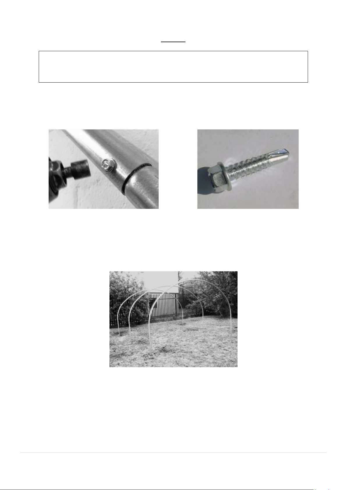
A Sheep House is not a difficult structure to construct, but the task at hand should not be taken lightly – After all, this
is a building that must stand up to extreme weather conditions year after year. This really is a two person ob.
The following is a Guide to the successful construction of your Sheep House. If you follow this Guide, you will have
many years of use with very little or no maintenance. Please use the Checklist supplied with your order, together with
this Guide, to help you identify the different parts of your Sheep House.
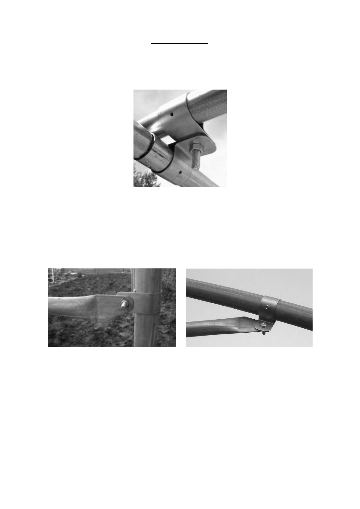
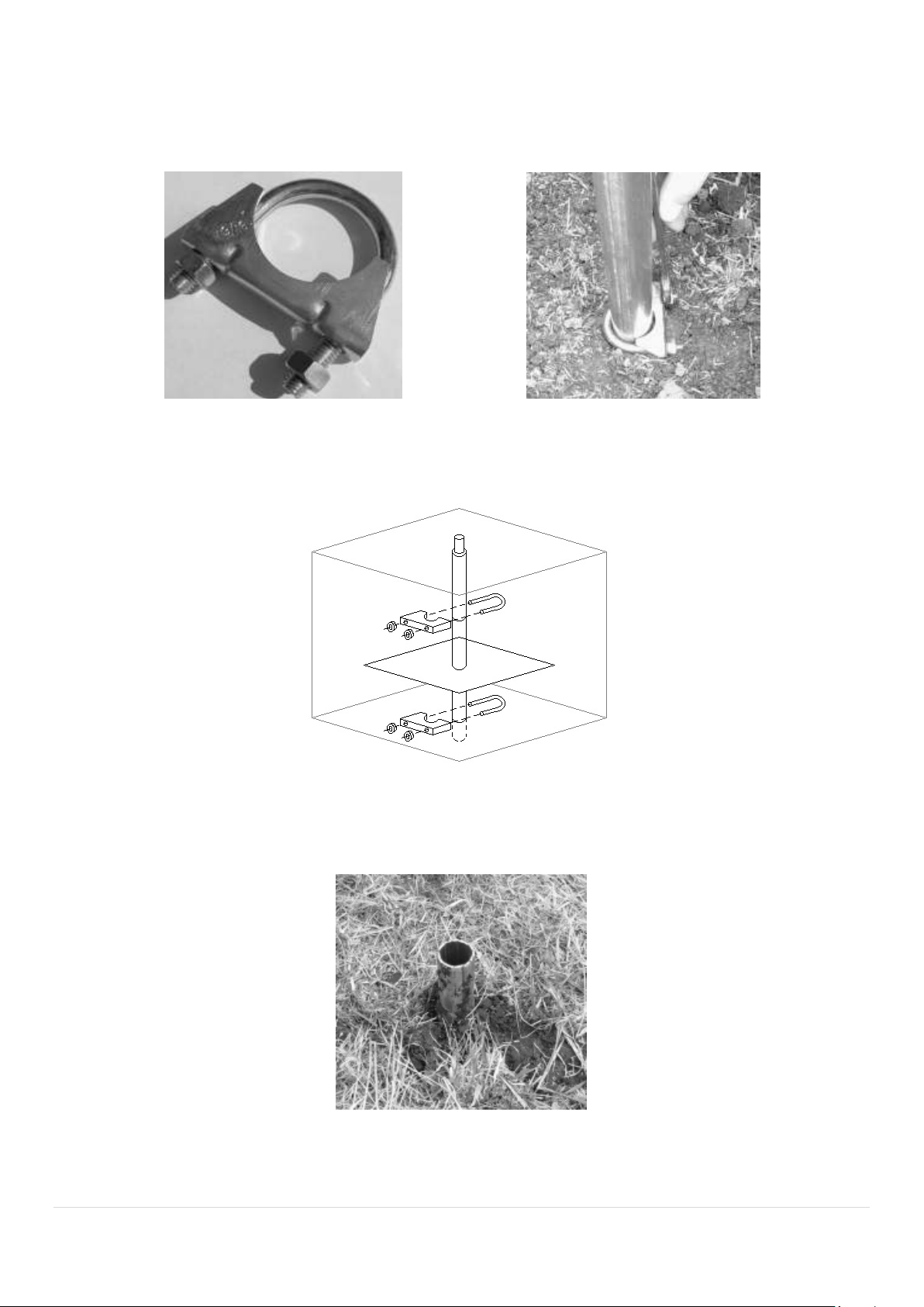
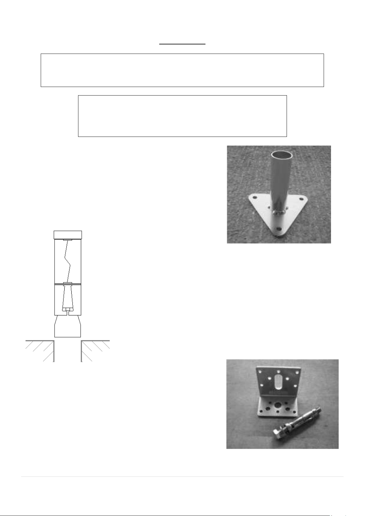
To help you identify the different steel tubes, the item codes on the Checklist relate to the diameter and length of
tube and how the ends are formed, eg;
“38/1810PP” is a 38mm diameter steel tube, 1810mm long, with plain ends.
“PS” at the end of the code would indicate the tube had one end plain and one end swaged.
“FP” would indicate the tube had one flattened and punched end and one end plain.
“FS” would indicate the tube had one flattened and punched end and one end swaged.
“FF” would indicate that both ends are flattened and punched.
“A” would indicate that the flattened ends are offset (at an angle) to each other.
“90” would indicate that the flattened ends are offset 90° to each other.
“B” would indicate that one of the flattened ends is bent to an angle.
Construction Videos
We have a full collection of online construction videos on our YouTube
channel.
Visit: https://www.youtube.com/c/PremierPolytunnels
Or scan the QR code opposite.
7 Day Construction Hel line
–
01282 811250
If you are unsure or confused about any aspect of construction, do not
hesitate to contact us.
Premier Polytunnels are proud to be the ONLY polytunnel supplier to offer
an out of hours Construction Helpline, available until 9pm, 7 days a week.

2 | P a g e
CONTENTS
SECTION PAGE
Introduction 3
Use of P Clips 4
Site 5
Foundation Tubes and Anchor Plates 6, 7 & 8
Base Plates 9
Hoops 10
Triple Ridge Kit 11 & 12
Corner Stabilisers 13 & 14
End Frames 15, 16 & 17
Timber Base Rails 18 & 19
Timber Side Rails and Ventilation Net 20
Forming a Rebate for the End Frame 21
Final Fix 22
Anti Hot Spot Tape 23
Covering the Sheep House 24, 25, 26, 27 & 28
TOOLS REQUIRED
***WARNING: PRODUCTS MAY CONTAIN SHARP EDGES.
ALWAYS WEAR GLOVES***
Here is a list of tools required to complete the construction of your polytunnel:
Tape measure Spade Large hammer Claw hammer
Spirit level 2x 13mm spanner Marker pen Battery drill
9mm drill bit 5mm drill bit Wood saw
String line Sharp knife Timber drift (small offcut of timber)
Large step ladders/Platform

3 | P a g e
INTRODUCTION
“Picture this....”
Below is a simple outline of what you should end up with once you have completed your pro ect and is something to
bear in mind while constructing your Sheep House.
A Sheep House is a series of hoops placed in line on Foundation Tubes or Base Plates.
A Ridge tube is suspended under the hoops at the centre point and runs the full length of the Sheep House.
Two additional Side Ridges are suspended under the hoops where the outer leg of the hoop oins the inner hoop.
Four diagonal tubular Stabilisers are placed one at each corner.
Two diagonal Roof Stabilisers are placed at each end to brace the roof of the Sheep House.
A timber End Frame with a 10ft opening is fixed central at each end.
Base Rails are placed around the frame at ground level.
Side Rails are placed around the frame 1m above the base rail.
Ventilation net is placed between the base and side rails
Polythene is placed over the framework and fixed around the End Frame. The polythene cover is then fixed to the Side
Rails.

4 | P a g e
USE OF ‘P’ CLIPS
The image below demonstrates the double ‘P’ Clip method used to fix the Triple Ridge.
The following images show how a Corner Stabiliser or any tube flattened and punched at the end attaches to a ‘P’ Clip.
NOTE: ‘P’ Clips should always be placed around a hoop so that the leg of the P is to the inside of the polytunnel – That
is to say, as far away from the polythene cover as possible.
***PLEASE NOTE: When assembling your olytunnel, no screws, bolts, ends of tubes, etc, should rotrude beyond
the hoo s as these will cause damage to your cover***

5 | P a g e
SITE
Your construction site should be clear and reasonably level from side to side. Approximately 6 inch out of level across
the width of the tunnel can be taken up by ad usting the Foundation Tubes of your Sheep House (Fig1).
Fig1
A slope down the length of the structure does not have to be taken into account as your Sheep House can be built
straight onto this slope with the framework placed at the vertical (Fig2).
Fig2

6 | P a g e
FOUNDATION TUBES and ANCHOR PLATES
Check List
code of parts required: 50/600PS
–
AP
6
0
–
50APC
Please use the Parts Check List supplied with your order, together with this Guide, to help you
identify the different parts of your polytunnel and confirm the quantities.
***IMPORTANT – Protect the ends of tubes from damage when driving them into lace by using a timber drift
(a small offcut of timber)***
All measurements are taken from the centre of the Foundation Tubes.
Foundation Tubes are driven into the ground at each end of each hoop.
Choose a corner of your Sheep House to be a fixed point from which all measurements will be taken and mark the
point with a peg or paint (it is advised that this fixed point is the highest corner of the structure on any sloping site).
Measure the length of your chosen Sheep House and mark this point. (All measurements are to the centre of the tube).
Mark out the remaining corners. The measurements for these will be the width and length of your Sheep House.
To check for square, measure from corner to corner (Fig 3)
– This measurement should be the same, but if not, simply
ad ust the marks until correct.
Fig3
Mark out the position for the remaining holes down the
length at 6ft spacing.
Dig a hole 20 inches square x 16 inches deep at all of the
marked points (Fig4).
Fig4

7 | P a g e
At the previously mentioned fixed point drive a Foundation Tube into the bottom of the hole until ust the swaged end
is left above ground level (Fig5).
Fig5
Set the three other corner Foundation Tubes, making sure all measurements are correct, checking for square and
checking that they are level across the width.
Drive in the rest of the Foundation Tubes at 6ft spacings along the length, using a string line to check the tops of the
tubes are at the right level and are inline.

8 | P a g e
Now all the foundations are knocked in, place an anchor plate clamp (Fig6) around the each of the foundation tubes
at the bottom of the holes (Fig7).
Fig6 Fig7
Slide an anchor plate over the tubes to rest on the clamps and tighten another clamp on top of the plates to hold in
position (Fig8).
Fig8
Place the soil back in the holes and heel down flat with the ground level (Fig9). Re-check all measurements.
Fig9

9 | P a g e
BASE PLATES
Check List code of parts required: 50BP
–
10LB
–
DPBPK
Please use the Parts Check List supplied with your order, together with this Guide, to help you
identify the different parts of your polytunnel and confirm the quantities.
Tools required:
Hammer drill 14mm masonry bit
16mm masonry bit 17mm spanner or socket
If you are placing your sheep house on a concrete base you will require
Base Plates (Fig10) which replace Foundation Tubes.
Please use the same method of measuring as for Foundation Tubes.
Fig10
When securing Base Plates to the ground, drill three 16mm holes (80mm deep
minimum) into the footing through the three Base Plate holes.
Insert the loose bolt sleeves into the holes until flush with the ground. Please make
sure to insert the sprung end of the sleeve first (Fig11).
Bolt the Base Plates onto the ground by tightening the loose bolts through the
holes on the Base Plates and into the sleeves.
Fig11
End Frame posts are secured at the base with an Angle Bracket (Fig12).
These require a 14mm hole to be drilled into the footing (70mm deep
minimum). Bolt these brackets down as you would Base Plates but with
only one loose bolt.
The End Frame posts then bolt to this bracket using the bolt supplied with
the Base Rails.
Fig12

10 | P a g e
HOOPS
Check List code of parts required: OH1618
–
IH1
6
PS
–
IH1
6
PP
–
5.5SDS
Please use the Parts Check List supplied with your order, together with this Guide, to help you
identify the different parts of your polytunnel and confirm the quantities.
Hoops come in four sections – two outer legs and two inner hoops. These sections should be slotted together on a flat
base and the oints held together using a self drill screw located approximately 40mm away from the oint (Fig13).
Fig13 Self Drill Screw
Lift the hoops into position on the foundations. The swaged half of the inner hoop should be kept to the same side of
the structure (left side or right side). Make sure the screws on the end hoops face the inside of the Sheep House
(Fig14).
Fig14
***Please note: Self drill screws should be held in the nut driver rovided or can be held directly into a drill chuck.
They will drill their own hole and ta themselves into osition.
Do not over-tighten***

11 | P a g e
TRIPLE RIDGE KIT
Check List code of parts required: 38/1830PP
–
38/1900PS
–
50P
–
38P
–
5.5SDS
–
38EC
Please use the Parts Check List supplied with your order, together with this Guide, to help you
identify the different parts of your polytunnel and confirm the quantities.
The centre Ridge bar is supplied in 6ft sections. One ridge starter with plain ends and one or more ridge extensions
with one swaged end.
Place a ‘P’ Clip around the top centre of each hoop. The central oint can be used as a guide.
On the end hoops the leg of the P should be to the inside edge of the hoop and should face down the length of the
Sheep House.
Place a ‘P’ Clip around one end of the ridge starter. Bolt this ridge starter up to the ‘P’ Clip on one of the end hoops
(Fig15).
Fig15
Ad ust the ridge starter until the end is located half way through the end hoop (Fig16).
Fig16
With the ridge starter suspended from the hoop slide a ridge extension into the starter. Place a ‘P’ Clip around the
ridge starter/extension wherever it crosses a hoop and bolt up to the ‘P’ Clip on the hoop. Do not tighten this bolt and
nut until a later stage.

12 | P a g e
Keep adding ridge extensions and ‘P’ Clips whenever they cross a hoop until you reach the opposite end of the Sheep
House. Bolting them up but not tightening.
Once the full centre Ridge has been suspended loosely, measure the spacings for the hoops using the end with the
ridge starter as the starting point. Ad ust the ‘P’ Clips along the Ridge until all the hoops are at 6ft spacings (Fig17).
Fig17
Ad ust the ‘P’ Clips on the hoops so that the Ridge runs in a straight line down the length, as close to centre as possible.
Once happy with the positions, tighten all the bolts and nuts and secure the ‘P’ Clips onto the Ridge and the hoops
using self drill screws.
Secure the ridge sections together using self drill screws located approximately 2cm away from the oins.
Fit a plastic end cap in each end of the Ridge.
Com leted centre ridge.
Tri le Ridge Kits:
These side Ridge bars are identical to the centre Ridge and should be assembled using the same
method. These side Ridges should be located close to where the outer legs meet the inner hoop.

13 | P a g e
CORNER STABILISERS
Check List code of parts
required: 38/2400FFA
BLACK & WHITE
–
50CSK
Please use the Parts Check List supplied with your order, together with this Guide, to help you
identify the different parts of your polytunnel and confirm the quantities.
These tubes are placed to form a triangle at each corner of the Sheep House (Fig18).
Fig18
Stabilisers are right and left handed for opposite corners of the Sheep House and have their flat ends offset to
accommodate the curve of the end hoop – The ‘RH’ pair are painted WHITE at the end and the ‘LH’ pair are painted
BLACK to differentiate between them.
Note: Right and left hand should be viewed from the outside of the Shee House looking at the end.

14 | P a g e
Place a ‘P’ Clip around the second to end hoop with the leg of the P towards the inside edge of the hoop and pointing
towards the end hoop. This ‘P’ Clip should be located 9 inches up from the ground. Bolt one end of a Corner Stabiliser
to this ‘P’ Clip but do not tighten (Fig19).
Fig19
Place a ‘P’ Clip around the end hoop, again with the leg towards the inside edge and pointing towards the second
hoop. Bolt the Corner Stabiliser to this ‘P’ Clip but do not tighten.
Check the ‘P’ Clip on the second to end hoop is still located 9 inches up from ground level, if it has moved then simply
slide the clip up or down the hoop until back in position. Tighten this ‘P’ Clip and secure with a self drill screw making
sure the head of the screw does not protrude past the hoop.
Using a spirit level to check the end hoop for vertical, slide the ‘P’ Clip up or down the hoop until in the correct position.
Tighten and secure the ‘P’ Clip using a self drill screw making sure the head of the screw does not protrude past the
hoop (Fig20).
The predrilled holes in the ‘P’ Clip may not be in a suitable location for the self-drill screw, but the screw will make its
own hole in a place suitably clear of the Polythene.
Fig20
Repeat this process at each corner of the Sheep House.

15 | P a g e
END FRAMES
Check List code of parts required: 16/18SHFK
–
CDFF
–
50NAIL
–
50DP
–
DPBPK (hard standing only)
– 38/750FF90B – 38P – M875 – DPBPK (hard standing only)
Please use the Parts Check List supplied with your order, together with this Guide, to help you
identify the different parts of your polytunnel and confirm the quantities.
4 inch x 2 inch timber is used for the End Frames. The 4 inch face of all the timbers, which make up the End Frame,
should face outwards.
Place a string line across the outside of the end hoop ust above ground level; this will act as a guide to keep the End
Frame in line with the hoop at the base.
Lay the 3.05m long length of 4 inch x 2 inch timber along the ground and centralise it between the end hoop legs.
Make a note of the measurement from the leg of the hoop to the end of the lintel (approximately 900mm).
At each end of the lintel dig a hole, a minimum of 12 inches deep. Hold a 3.6m length of timber vertical with one end
placed in the hole (with the 4 inch face of the timber facing outwards). Check that the measurement you noted earlier
is maintained from the hoop leg to the INSIDE edge of this post. Check the timber for vertical and mark under the
hoop – cut the timber on this mark.
Re-set the timber post in the hole and using a ‘P’ Clip – with the leg of the P down the back of the post – bolt in position
but do not tighten. Back fill the hole keeping the post vertical and in line with the end hoop (Fig21).
***Please Note: When lacing the Shee House on a hard standing base, Angle Brackets should be used to
secure the bottom of the osts (see Fig12 on age 9)***
Double check the post for vertical and ad ust the ‘P’ Clip along the hoop if necessary before securing to the hoop with
a self drill screw.
Fig21

16 | P a g e
Your first post is now in position from which the rest of the End Frame is constructed. Repeat the previous operation
with the second post but leave it hanging loose in the hole with the ‘P’ Clip unsecured (Fig22).
Fig22
Using the 3.05m long timber lintel as a gauge, place this between the posts at the base. Ad ust the loose post into
position touching the gauge and in line with the end hoop. Back fill the hole.
The timber lintel is now lifted to your desired height between the posts.
Drill a 5-7mm hole through the side of the fixed post in line with the centre of the lintel. Drive a 6 inch nail through
the pre-drilled hole and into the end of the lintel.
Using a spirit level, keep the lintel level horizontally between the two posts. Ad ust the loose second post along the
hoop until tight up to the lintel. Drill a 5mm hole through the post and drive a 6 inch nail through the post and into the
lintel (checking at all times that the lintel is level horizontally). Tighten and secure the ‘P’ Clip on the loose post and
place a nail plate over each side of each oint (Fig23).
Fig23

17 | P a g e
A Lintel Stabiliser angles down from the centre Ridge to the centre of the lintel (Fig24).
Fig24
Place a ‘P’ Clip around the centre Ridge and loosely bolt the Lintel Stabiliser to it.
Slide the ‘P’ Clip along the Ridge until the angled end of the Stabiliser meets the lintel. Drill a 9mm hole through the
hole on the Stabiliser and the timber lintel. Bolt the Stabiliser to the lintel with an M8 x 75 cup square bolt through the
drilled hole (Fig25).
Fig25
Ad ust the ‘P’ Clip along the Ridge until the lintel doesn’t bow in or out of the polytunnel. Tighten and secure the ‘P’
Clip with a self drill screw.
Repeat this process at the opposite end of the Sheep House.

18 | P a g e
TIMBER BASE RAILS
Check List code of parts required: 31536TIM
–
50SRC
–
50TCB
–
NP
–
40NAIL
Please use the Parts Check List supplied with your order, together with this Guide, to help you
identify the different parts of your polytunnel and confirm the quantities.
3 inch x 1½ inch timber is used for the timber Base Rails.
This timber rail goes around the outside of the Sheep House framework at ground level and finishes at the posts of
the End Frames (Fig26).
Fig26
The rails which make up the sides of the Sheep House are placed end to end and fixed at each hoop.
At each intermediate hoop a ‘saddle clamp’ is used to fix the timber rails to the hoop (Fig27).
At the corners a corner bracket should be placed around the hoop and the timber rails bolted through this bracket
(Fig28).
Fig27 Fig28

19 | P a g e
These side timbers should be left overhanging by at least 2 inches at each end. Wherever a oint in the rail occurs, a
nail plate should be nailed across the oint on the inside (Fig29).
Fig29
Cut a length of timber to fit across the front of each End Frame post and butt up to the overhanging side timber.
To attach the end timber to the End Frame post, drill a 9mm hole through the end timber and post and bolt in place
with a 75mm cup bolt with a washer under the nut on the inside (Fig30).
If the structure is being placed onto hard standing then drill the 9mm hole through the Angle Bracket on the inside of
the post and through the end timber. The 75mm bolt then fixes the end timber, post and Angle Bracket together.
Fig30
At the outer corners, bolt the timber to the corner bracket (Fig28 on age 19).
Nail a 3 inch nail through the side timber and into the end timber and cut off the overhang.

20 | P a g e
TIMBER SIDE RAILS and VENTILATION NET
Check List code of parts required: 31536TIM
–
193824BAT
–
50NAIL
–
NP
–
40NAIL
–
50SRC
–
50TCB
– 1NET
Please use the Parts Check List supplied with your order, together with this Guide, to help you
identify the different parts of your polytunnel and confirm the quantities.
Timber Side Rails are identical to timber Base Rails and should be fixed using the same method (see ‘Timber Base Rail’
section on page 18) but placed 1m from the ground on the straight side of the Sheep House leg (Fig31).
Fig31
The Ventilation Net should be trapped between the timber Side
Rail and the rebate batten, along the top edge of the Side Rail
(leaving some excess at each end) from post to post (Fig32).
Fig32
Once you have formed the rebate all the way around from post to post it is necessary to cut off (at an angle) any rebate
that protrudes at the corners (Fig33).
Fig33
Table of contents
Other Premier Farm Equipment manuals