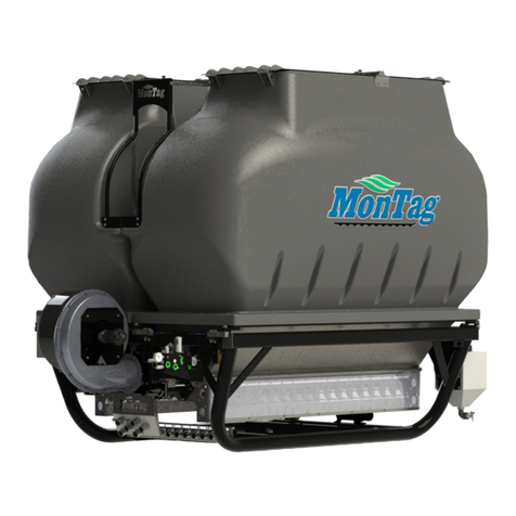
Montag GEN 1 User manual

Gen 1 Operations Manual
P003167- Effective 1-1-2020 thru current
Read manual before operating Montag equipment
MONTAG MANUFACTURING, INC.
3816 461ST AVE
EMMETSBURG, IA 50536
www.montagmfg.com
PH 712-852-4574


3
1. Introduction / General Information ........................................................................................... 5
1.1 Introduction ..........................................................................................................................................5
1.2 Hydraulic Requirements .......................................................................................................................5
.......................................................................................................................................5
1.3.1 Dry Fertilizer Meter - GEN 1 ........................................................................................................5
...........................................................................................................................5
.................................................................................................................6
.................................................................................................................7
1.7 Gen 1 - Rate Capacity Chart ................................................................................................................8
1.8 Warranty Information ............................................................................................................................9
2. Safety ........................................................................................................................................ 10
2.1 Section Overview................................................................................................................................10
2.2 Safety ................................................................................................................................................10
2.2.1 Keep All Guards In Place...........................................................................................................11
2.2.2 Stay Away From Rotating Augers .............................................................................................11
.......................................................................................................11
2.2.4 Avoid Hot Parts ..........................................................................................................................12
2.2.5 Avoid High Pressure Hydraulic Fluid .........................................................................................12
2.2.6 Avoid Flying Object Injuries .......................................................................................................12
2.2.7 Avoid Loss Of Control ................................................................................................................12
2.2.8 Avoid Tipping Cart......................................................................................................................13
2.2.9 Clearance ..................................................................................................................................13
2.2.10 Maintenance ............................................................................................................................13
2.2.11 Hazards From Modifying Your Fertilizer Applicator..................................................................14
2.2.12 Safety Warning Label Locations .............................................................................................14
2.2.13 Safety Warning Labels.............................................................................................................15
2.2.14 Safety Decal Care....................................................................................................................18
2.2.15 Tire Safety................................................................................................................................18
2.2.16 Lighting And Marking ...............................................................................................................18
2.3 Highway And Transportation Operation..............................................................................................18
3. Assembly.................................................................................................................................... 20
3.1 Gen 1 System Assembly ....................................................................................................................20
3.1.1 Install Gen 1 On Cart (Without Optional Weigh Bars) ...............................................................20
3.1.2 Install Gen 1 On Cart (With Optional Weigh Bars) ....................................................................20
3.1.3 Install Step and Platform Assembly ..........................................................................................22
3.1.4 Install Lights...............................................................................................................................23
3.1.5 Install Air Pressure Gauge.........................................................................................................23
3.1.6 Install Row Reducer Installation (Optional)................................................................................23
4. Connect Cart To Implement...................................................................................................... 24
4.1 Connect Cart To Implement................................................................................................................24
4.1.1 Connect Cart (Standard Cart With Ball Hitch) ...........................................................................24
4.1.2 Connect Cart (Standard Cart With Knuckle Hitch).....................................................................24
4.1.3 Align Cart ...................................................................................................................................25
4.2 GEN 1 System ...................................................................................................................................25
4.2.1 Connect Hydraulic Hoses ..........................................................................................................25
4.2.2 Connect Air Hoses.....................................................................................................................26
4.2.3 Connect Customer Supplied Controller .....................................................................................28
4.2.4 Operations .......................................................................................................................................28
4.2.5 Fill Fertilizer Tank.............................................................................................................................28
5. Disconnecting From Implement............................................................................................... 30
5.1 Disconnect From Implement - GEN 1.................................................................................................30
5.1.1 Disconnect GEN 1 System ........................................................................................................30
5.1.2 Disconnect Cart From Implement..............................................................................................30

4
6. Troubleshooting ........................................................................................................................ 31
6.1 Troubleshooting GEN 1 ......................................................................................................................31
6.1.1 GEN 1 Troubleshooting Chart....................................................................................................31
6.1.2 Eliminating Auger Obstructions (GEN 1 Only)...........................................................................35
6.1.3 Clearing Air Passages (GEN 1 Only).........................................................................................36
7. Routine Maintenance ................................................................................................................ 38
7.1 Section Overview................................................................................................................................38
7.2 End Of Season Inspections ................................................................................................................38
7.3 Lubrication ..........................................................................................................................................38
7.4 Inspect Caulk Seal Between Meter And Tank (GEN 1 Only) ..............................................................38
8. Storage ....................................................................................................................................... 39
8.1 Storing The GEN 1 System ................................................................................................................39
9. Service And Repair.................................................................................................................... 40
9.1 Fan .....................................................................................................................................................40
9.2 Fan Drive Motor..................................................................................................................................41
9.3 Auger Bearings ...................................................................................................................................42
9.4 Replacing Load Cells On GEN 1I ......................................................................................................42
10. Parts ........................................................................................................................................ 43
10.1 Replacement Parts ...........................................................................................................................43
11. Appendix .................................................................................................................................. 44
11.1 Controller Calibration Chart - GEN 1 ................................................................................................44
Calibration Information - GEN 1..........................................................................................................44
..........................................................................45
11.3 Hydraulic Schematics - GEN 1 One Section ....................................................................................47
11.4 Hydraulic Schematics - GEN 1 Two Section.....................................................................................48
11.5 Electrical Connectors ........................................................................................................................49

5
1.1 INTRODUCTION
Read and understand this manual before using your fertilizer applicator, and follow all of the safety instructions. Keep all
manuals in a safe place inside your tractor at all times.
Some components on your fertilizer applicator may have separate instruction manuals. Where this manual indicates
that you should read another manual, and you do not have that manual, contact your dealer or Montag Manufacturing for
assistance.
Information provided in this manual was current as of the issue date. Montag Manufacturing reserves the right to make
design changes without further notice or liability.
1.2 HYDRAULIC REQUIREMENTS
The following tractor hydraulic capacity requirements apply for any dry fertilizer application.
Model Rows Hydraulic Capacity Hydraulic Pressure Minimum Hydraulic Hose Size
Pressure Return Case Drain
GEN 1 16 gpm (61 lpm) 2500 psi (172 bar) ½ inch ¾ inch ½ inch
GEN 1 16 18 gpm (68 lpm) 2600 psi (179 bar) ¾ inch ¾ inch ½ inch
GEN 1 20 gpm (76 lpm) 2850 psi (197 bar) ¾ inch 1 inch ½ inch
1.3 SPECIFICATIONS
1.3.1 DRY FERTILIZER METER - GEN 1
Model Maximum Rated Capacity Minimum Rated Capacity Hose Size
Standard Meter
8 Row Standard 500 lbs. /Acre @ 5 mph* 50 lbs. /Acre @ 5 mph* 2 inch
12 Row Standard 500 lbs. /Acre @ 5 mph* 50 lbs. /Acre @ 5 mph* 2 inch
16 Row Standard 500 lbs. /Acre @ 5 mph* 50 lbs. /Acre @ 5 mph* 2 inch
18 Row Standard 400 lbs. /Acre @ 5 mph* 50 lbs. /Acre @ 5 mph* 2 inch
High Output Meter
8 Row High Output 800 lbs. /Acre @ 5 mph* 100 lbs. /Acre @ 5 mph* 2½ inch
12 Row High Output 800 lbs. /Acre @ 5 mph* 100 lbs. /Acre @ 5 mph* 2½ inch
16 Row High Output 800 lbs. /Acre @ 5 mph* 100 lbs. /Acre @ 5 mph* 2½ inch
18 Row High Output 500 lbs. /Acre @ 5 mph* 100 lbs. /Acre @ 5 mph* 2½ inch
24 Row High Output 500 lbs. /Acre @ 5 mph* 100 lbs. /Acre @ 5 mph* 2½ inch
* Capacities are based on fertilizer weighing 64 lbs./cubic ft. and 30” row spacing with standard hose length equipped with
cart.
1.4 MACHINE IDENTIFICATION
#21593, #21643 to Current
Gen 1 serial tag is located on the motor side of the fan.
My serial number is
1. IntroductIon / General InformatIon

6
Published 02/04/2021
*Calculated using 64 lb/ft3product density [1.025 kg/L]
†Calculated using 64 lb/ft3product density, 30 in row spacing, and 5 mph [1.025 kg/L, 76 cm row spacing, and 8 km/h]
‡Unloaded, dry weight
§Hydraulic capacity and pressure dependent on row configuration.
185 CuFt (
6 Ton) GEN 1
Base Unit with a white bin on a Montag
Auto
-
Steer Cart shown above. Other color options include gray
and yellow (see image below). Bins have two fill inlets. All units
use the Montag G
EN 1 particulate metering technology.
66TToonnGGEENN11SSppeecciiffiiccaattiioonnss
Row Configurable:
8, 12, 16, 18, & 24 rows
2
Section Configurable for 16, 18, & 24 row meters
Product Capacity:
185 ft3[5,239 L] / 5.92 ton [5,371 kg]*
Rate Capacity
†:
STD
H.O.
Rows
lb/ac
kg/ha
Rows
lb/ac
kg/ha
8-16
50-500
56-560
8-16
100-800
112-897
18
50-400
56-448
18-24
100-500
112-560
Weight
‡: 1,800 lb [817 kg]
Overall Height:
85.4 in [216.9 cm]
Overall Length:
107.9 in [274.1 cm]
Overall Width:
102.8 in [261.1 cm]
Product Fill Height: 77.
8 in [197.6 cm]
Product Fill Inlet Size: 7
.56 ft2[0.70m2]
Product Outlet
Hose Size:
STD - 2.00 in [5.08 cm]
H.O. - 2.50 in [6.35 cm]
Req.
Hydraulic Capacity§:
16-20 gpm [61-76 Lpm]
Req. Hydraulic Press
ure§:
2,500-2,850 psi [172-197 bar]
Configurable
with any Montag 6, 9, or 12 ton
Auto-Steer Carts
MMOONNTTAAGGMMAANNUUFFAACCTTUURRIINNGG
3816 461
st Avenue, Emmetsburg, IA 50536
1.5 GEN 1 - 6 TON SPECIFICATIONS

7
Published 02/04/2021
*Calculated using 64 lb/ft3product density [1.025 kg/L]
†Calculated using 64 lb/ft3product density, 30 in row spacing, and 5 mph [1.025 kg/L, 76 cm row spacing, and 8 km/h]
‡Unloaded, dry weight
§Hydraulic capacity and pressure dependent on row configuration.
9
Ton GEN 1 Base Unit with a gray bin on a Montag Auto-
Steer
Cart shown above. Other color options include
white
and yellow
(see image below). Bins have two fill inlets. All units use the
Montag G
EN 1 particulate metering technology.
99TToonnGGEENN11SSppeecciiffiiccaattiioonnss
Row Configurable:
8, 12, 16, 18, & 24 rows
2
Section Configurable for 16, 18, & 24 row meters
Product Capacity:
280 ft3[7,929 L] / 8.96 ton [8,128 kg]*
Rate Capacity
†:
STD
H.O.
Rows
lb/ac
kg/ha
Rows
lb/ac
kg/ha
8-16
50-500
56-560
8-16
100-800
112-897
18
50-400
56-448
18-24
100-500
112-560
Weight
‡: 2,200 lb [998 kg]
Overall Height:
108.8 in [276.4 cm]
Overall Length:
126.9 in [322.3 cm]
Overall Width:
103.3 in [262.4 cm]
Product Fill Height:
101.2 in [257.0 cm]
Product Fill Inlet Size: 7
.56 ft2[0.70m2]
Product Outlet
Hose Size:
STD - 2.00 in [5.08 cm]
H.O. - 2.50 in [6.35 cm]
Req.
Hydraulic Capacity§:
16-20 gpm [61-76 Lpm]
Req. Hydraulic Press
ure§:
2,500-2,850 psi [172-197 bar]
Configurable with Montag 9 or 12 ton
Auto-Steer Carts
MMOONNTTAAGGMMAANNUUFFAACCTTUURRIINNGG
3816 461
st Avenue, Emmetsburg, IA 50536
1.6 GEN 1 - 9 TON SPECIFICATIONS

8
Montag Gen 1 Rate Capacity Chart
Speed Max. Rate Speed Max. Rate Speed Max. Rate Speed Max. Rate Speed Max. Rate Speed Max. Rate
10 290 10 400 10 440 10 180 10 250 10 275
8360 8500 8545 8225 8310 8340
6480 6665 6725 6300 6415 6455
4720 41000 41095 4450 4625 4685
10 180 10 250 10 275 10 145 10 200 10 220
8225 8310 8340 8180 8250 8275
6300 6415 6455 6235 6330 6360
4450 4625 4685 4360 4500 4545
Speed Min. Rate Speed Min. Rate Speed Min. Rate Speed Min. Rate Speed Min. Rate Speed Min. Rate
10 18 10 25 10 27 10 910 13 10 14
823 832 835 812 816 818
630 642 646 615 621 623
445 463 469 423 432 435
Gen 1 MMaaxxiimmuummRate by Speed (30" Row)
Gen 1 HO Meter (8-16 rows) Gen 1 STD Meter (8-16 rows)
Urea
(46
lb/ft
3
)MAP
(64
lb/ft
3
)Potash (70
lb/ft
3
)Urea
(46
lb/ft
3
)MAP
(64
lb/ft
3
)Potash (70
lb/ft
3
)
Gen 1 MMiinniimmuummRate by Speed (30" Row)
Gen 1 HO Meter
Gen 1 STD Meter
Urea
(46
lb/ft
3
)
MAP
(64
lb/ft
3
)
Potash (70
lb/ft
3
)
Gen 1 HO Meter (18 & 24 rows)
Gen 1 STD Meter (18 & 24 rows)
Urea
(46
lb/ft
3
)
MAP
(64
lb/ft
3
)
Potash (70
lb/ft
3
)
150
250
350
450
550
650
750
850
950
1050
1150
4 5 6 7 8 9 10
Max. Rate (lb/ac)
Speed (mph)
Maximum Rate by Speed
Gen 1 High Output (2.5") Meter
Urea (8-16 Rows) MAP (8-16 Rows) Potash (8-16 Rows)
Urea (18-24 Rows) MAP (18-24 Rows) Potash (18-24 Rows)
100
150
200
250
300
350
400
450
500
550
600
650
700
45678910
Max. Rate (lb/ac)
Speed (mph)
Maximum Rate by Speed
Gen 1 Standard (2") Meter
Urea (8-16 Rows) MAP (8-16 Rows) Potash (8-16 Rows)
Urea (18-24 Rows) MAP (18-24 Rows) Potash (18-24 Rows)
5
15
25
35
45
55
65
4 5 6 7 8 9 10
Min. Rate (lb/ac)
Speed (mph)
Minimum Rate By Speed
Gen 1 High Output (2.5") Meter
Urea MAP Potash
0
5
10
15
20
25
30
35
45678910
Min. Rate (lb/ac)
Speed (mph)
Minimum Rate By Speed
Gen 1 Standard (2") Meter
Urea MAP Potash
www.montagmfg.com Published 2/4/2021
1.7 GEN 1 - RATE CAPACITY CHART

9
1.8 WARRANTY INFORMATION
MONTAG MANUFACTURING, INC.
LIMITED WARRANTY FOR NEW MONTAG EQUIPMENT
What this Limited Warranty Covers - Montag Manufacturing, Inc. (“Montag”) warrants equipment manufactured by it to
be free from defects in material and workmanship for the warranty period.
What this Limited Warranty Does Not Cover - Montag is not responsible for, and this limited warranty does not cover:
caused by normal wear and tear, (4) unauthorized repair or adjustments, (5) reimbursement for work completed by an
unauthorized service center, (6) other equipment, crops, or property with which Montag equipment comes into contact,
(7) components manufactured and warranted by other manufacturers such as tires and hydraulic equipment, (8) loss
of time, loss of use, towing charges, or other incidental or consequential damages, or (9) to equipment which has been
damaged as the result of, misuse, abuse, lack of proper protection during storage, accident, failure to follow the operating
contingencies beyond Montag’s control.
Warranty Term and Coverage - This limited warranty provides coverage for three years from the date the equipment is
What Montag Will Do – (1) Montag will provide telephone consultation with a trained representative regardless of the
location of the equipment. (2) For equipment located in the general geographic area served by a Montag dealer, Montag
of business. (3) Equipment that requires service or repair at the Montag manufacturing facility or at an authorized Montag
dealership must be transported or shipped to and from the Montag manufacturing facility or Montag authorized dealership
To Get Warranty Service – To get warranty service the owner must (1) report the defect to an authorized dealer and
request repair within the warranty term, (2) present evidence of the warranty start date, and (3) make the product available
to the dealer within a reasonable time. The owner can also contact Montag by U.S. Mail at 3816 461st Ave. Emmetsburg,
Iowa 50536; by telephone at (712)-852-4572; by facsimile at (712)-852-4574; or by e-mail at [email protected]
Limitation of Implied Warranties and Other Remedies –
representations or promises as to the quality, performance or freedom from defect of its equipment covered by this
limited warranty. IMPLIED WARRANTIES OF MERCHANTABILITY AND FITNESS FOR A PARTICULAR PURPOSE TO
THE EXTENT APPLICABLE, SHALL BE LIMITED IN DURATION TO THE APPLICABLE PERIOD OF WARRANTY SET
FORTH IN THIS LIMITED WARRANTY. THE OWNER’S ONLY REMEDIES IN CONNECTION WITH THE BREACH OR
PERFORMANCE OF ANY WARRANTY ARE SET FORTH IN THIS LIMITED WARRANTY. IN NO EVENT WILL MONTAG
OR ANY MONTAG DEALER BE LIABLE FOR INCIDENTAL OR CONSEQUENTIAL DAMAGES. (Note: Some states do
have other rights which vary from state to state.
No Dealer Warranty – The selling dealer makes no warranty of its own and the dealer has no authority to make any
representation on behalf of Montag, or to modify the terms or limitations of this warranty in any way.

10
2.1 SECTION OVERVIEW
2.2 SAFETY
This Owner’s Manual covers the particulate metering system produced by Montag Manufacturing. Before operating or
servicing the fertilizer applicator, you must read, understand and follow the instructions and safety warnings in this manual.
Your fertilizer applicator may not be equipped with some of the optional equipment shown in the illustrations in this manual.
Montag Manufacturing urges the consumer to make safety the highest priority when using this machine. Do not attempt
is impaired.
This equipment is dangerous to children and persons unfamiliar with its operation. The operator should be a responsible
adult familiar with farm machinery and trained in this equipment's operations. Do not allow persons to operate or
assemble this unit until they have read this manual and have developed a thorough understanding of the safety
precautions and of how it works.
The safety information in this manual is denoted by the safety alert symbol:
This symbol means ATTENTION! BECOME ALERT! YOUR SAFETY IS INVOLVED!
The level of risk is indicated by the following signal words.
Indicates an imminently hazardous situation that, if not avoided, will result in death or serious
injury. This signal word is to be limited to the most extreme situations typically for machine
components which, for functional purposes, cannot be guarded.
Indicates a potentially hazardous situation that, if not avoided, could result in death or serious
injury, and includes hazards that are exposed when guards are removed. It may also be used to
alert against unsafe practices.
Indicates a potentially hazardous situation that, if not avoided, may result in minor or moderate
injury. It may also be used to alert against unsafe practices.
Indicates a situation that could result in damage to the machine or other property.
2. Safety

11
2.2.1 KEEP ALL GUARDS IN PLACE
Remove guards only for adjustment and maintenance, install immediately when task is completed. Do not operate meter
Severing hazard.
Rotating fans and shafts can sever digits.
Always keep all guards and shields in place.
2.2.2 STAY AWAY FROM ROTATING AUGERS
Severing hazard.
Rotating augers can sever digits.
Remove chain from auger drive sprocket before touching
metering augers.
2.2.3 KEEP RIDERS OFF EQUIPMENT
may result in death or serious injury. Never climb on equipment while equipment is moving. Keep children away from
equipment at all times.
Never climb onto cart when it is not attached to an implement. Cart could tip, which may result in death or serious injury.
Crushing hazard.
Riders can fall from equipment, resulting in death or serious injury.
Never allow riders on the equipment.
Never climb on cart not attached to implement.

12
2.2.4 AVOID HOT PARTS
Burn hazard.
Do not touch hot hydraulic surfaces.
Do not work on hydraulic system when it is hot.
2.2.5 AVOID HIGH PRESSURE HYDRAULIC FLUID
Always relieve hydraulic system pressure before performing any work on the system. Use a piece of cardboard or paper,
not your hand, to check for leaks.
Relieve pressure before disconnecting hydraulic lines.
Makesurehydraulicuidconnectionsaretightandallhydraulichosesandlinesare
in good condition before applying pressure to the system. Use a piece of paper or
cardboard, NOT BODY PARTS, to check for suspected leaks. Wear protective gloves
and safety glasses or goggles when working with hydraulic systems. DO NOT DELAY!
If an accident occurs, see a doctor familiar with this type of injury immediately Any
uidinjectedintotheskinoreyesmustbetreatedwithinafewhoursorgangrenemay
result.
2.2.6 AVOID FLYING OBJECT INJURIES
When fan is running, debris can be thrown from the air outlet, causing injury or possible loss of sight.
Projectile hazard.
Do not stand in front of air outlet while fan is operating.
2.2.7 AVOID LOSS OF CONTROL
Danger of loss of control when transporting cart.

13
Remove all product from tank before transporting on roads. With empty tanks, maximum
speed for cart on roads is 20 mph.
2.2.8 AVOID TIPPING CART
If stairs and platform are installed on rear of dry tank, cart can tip over if people climb on stairs with cart disconnected from
implement, resulting in death or serious injury.
Crushing hazard.
Do not climb on tank stairs or platform when cart is disconnected from implement.
2.2.9 CLEARANCE
Collision hazard.
Know the height, width and length of the equipment.
Always be aware of clearances.
2.2.10 MAINTENANCE
Crushing hazard.
Good maintenance is your responsibility. Poor Maintenance is an invitation to trouble.
With careful inspection and routine maintenance, costly downtime and repairs can be
avoided.
Some parts and assemblies can be quite heavy. Before attempting to unfasten any part
or assembly, arrange to support it by means of a hoist, blocking, or by using an adequate
arrangement to keep it from falling, tipping, swinging, or moving in any manner which
may hurt somebody or damage the equipment.
Always use lifting equipment that is adequately rated to do the job. Never lift equipment
over people.
Be certain all moving parts on attachments have come to a complete stop before
attempting to perform maintenance.

14
Always use the proper tools or equipment for the job at hand.
After servicing, be sure all tools, parts, and service equipment are removed.
Before performing inspections, service or maintenance:
• Parktheequipmentonrm,levelsurface.
• Placetractortransmissioninpark,turntractorengineoandremoveignitionkey.
• Verify service locks are properly engaged or lower tool bar and lower row units to
the ground or pavement.
2.2.11 HAZARDS FROM MODIFYING YOUR PARTICULATE METERING SYSTEM
Before making any alteration, contact your dealer or Montag Manufacturing and describe the alteration you are
contemplating. Altering may void the manufacturer’s warranty. Montag Manufacturing does not accept any liability for
injury or damage.
2.2.12 SAFETY WARNING LABEL LOCATIONS - GEN 1
Fan Housing
Top Of Tank

15
2.2.13 SAFETY WARNING LABELS
Label A
2. Safety
Auger Motor
Label B

16
Label C
Label D

17
Label E
Label F
To protect against death or serious injury, all labels must be on the machine and must
be legible.
If any of these labels are missing or cannot be read, call Montag Manufacturing at 1-712-

18
2.2.14 SAFETY DECAL CARE
• Keep safety signs clean and legible at all times.
• Replace safety signs that are missing or have become illegible.
• Replaced parts that displayed a safety sign should also display the current sign.
• Safety signs are available from your Distributor or Dealer Parts Department or the factory.
How to Install Safety Signs:
• Be sure that the installation area is clean and dry.
•
• Remove the smallest portion of the split backing paper.
•
• Slowly peel back the remaining paper and carefully smooth the remaining portion of the decal in place.
• Small air pockets can be pierced with a pin and smoothed out using the piece of decal backing paper.
2.2.15 TIRE SAFETY
•
in serious injury or death.
•
•
or mount tires.
•
placed on the equipment.
• The rims and tires should be mounted on the cart with the valve stem to the outside. Be sure you have proper tire
2.2.16 LIGHTING AND MARKING
• It is the responsibility of the customer to know the lighting and marking requirements of the local highway authorities and
at night or during periods of limited visibility.
• Lighting kits are available from your dealer or from the manufacturer.
2.3 HIGHWAY AND TRANSPORT OPERATIONS
• Adopt safe driving practices:
• Keep the brake pedals latched together at all times. NEVER USE INDEPENDENT BRAKING WITH MACHINE
IN TOW AS LOSS OF CONTROL AND/OR UPSET OF UNIT CAN RESULT.
• Always drive at a safe speed relative to local conditions and ensure that your speed is low enough for an emergency
stop to be safe and secure. Keep speed to a minimum.
• Reduce speed prior to turns to avoid the risk of overturning.
• Avoid sudden uphill turns on steep slopes.
• Always keep the tractor or towing vehicle in gear to provide engine braking when going downhill. Do not coast.
• Do not drink and drive!
• Comply with state and local laws governing highway safety and movement of farm machinery on public roads.
•
highway during daylight and nighttime transport. Various safety lights and devices are available from your dealer.
•
laws should be checked for all highway lighting and marking requirements.
•
•
•
etc.
• Be observant of bridge loading ratings. Do not cross bridges rated lower than the gross weight at which you are
operating.
• Watch for obstructions overhead and to the side while transporting.

19
•
length and weight of the equipment when making turns, stopping the unit, etc.
•
hillsides.
•
• Maneuver the tractor or towing vehicle at safe speeds.
• Avoid overhead wires or other obstacles. Contact with overhead lines could cause serious injury or death.
•
• Allow for unit length when making turns.
• Operate the towing vehicle from the operator’s seat only.
• Never stand alongside of unit with engine running or attempt to start engine and/or operate machine while standing
alongside of unit.
• Never leave running equipment attachments unattended.
• As a precaution, always recheck the hardware on equipment following every 100 hours of operation. Correct all
problems. Follow the maintenance safety procedures.

20
3.1 GEN 1 SYSTEM ASSEMBLY
3.1.1 INSTALL GEN 1 ON CART (WITHOUT OPTIONAL WEIGH BARS)
Prevent death or serious injury.
Dry fertilizer metering unit weighs approximately 2200 lbs (998 kg).
Use adequate lifting and support devices.
1. Carefully position unit onto cart, with meter frame fully
other.
Note: Install U-bolts facing up, with nuts on top. If U-bolts are
installed facing down, and need to be removed for any reason,
tank unit disassembly may be required.
2.
of metering unit between unit bracket (A) and cart bracket
(B) as shown, with lock nuts on top. Tighten lock nuts until
they each contact the plate.
3. Alternate tightening nuts on each leg of U-bolt in 25 lb/ft
(34 Nm) increments until each nut is tightened to 75 lb/ft
(102 Nm) of torque. Then tighten each nut to 95 lb/ft (129 Nm) of torque. Avoid over tightening either side.
3.1.2 INSTALL GEN 1 UNIT ON CART (WITH OPTIONAL WEIGH BARS)
1. Position weigh bars (A) on cart brackets at each corner with
arrows on ends of weigh bars pointing down. Ends of bars
with arrows must be farthest from cart center frame (B).
2.
bolts (C), through two bolt holes closest together, and ¾
inch lock nuts. Do not tighten at this time.
Prevent death or serious injury.
Fertilizer metering unit weighs
approximately 2200 lbs (998 kg).
Use adequate lifting and support devices.
3. Position unit with fertilizer tank onto cart, with unit bolt holes
aligned with bolt holes in four weigh bars.
4.
corner through frame brackets and weigh bars. Tighten
bolts to 220 lb/ft (271 Nm) of torque.
3. aSSembly
Table of contents
Other Montag Farm Equipment manuals
Popular Farm Equipment manuals by other brands

Blue Diamond
Blue Diamond MOLDBOARD PLOW 440012 Operation and maintenance manual

woodmizer
woodmizer Sawmill Safety, Operation, Maintenance & Parts Manual

DALBO
DALBO CULTITRAIL 500 manual

Tube-Line
Tube-Line BF5000SL Operator's manual

Generac Power Systems
Generac Power Systems Powerwagon owner's manual

Metalcraft
Metalcraft TFA11 quick start guide