Lipco HSA 10 User manual


Instructions
Hydraulic shaker HSA 10
2 - 28
220018-00-EN BA HSA 10 / 28.09.2019
1. Introduction
Dear Customer,
We thank you for having chosen a LIPCO hydraulic shaker HAS 10.
We hope that you will be happy with your choice.
In order that your LIPCO hydraulic shaker HAS 10 will serve you well
for many years, we ask you to pay close attention to the operating
instruction, which you will find in this manual. This will help you to pre-
vent breakdowns and accidents resulting from non-observance of the
operating instructions, for which our company will not accept respon-
sibility.
This Instruction and Maintenance Manual is to be considered as an
integral part of the machine itself and therefore it must always accom-
pany the machine when it is sold, even in the event of its sale to third
parties.
If you keep this manual in a safe place and in good condition, you -
and whoever must use the machine - will always be able to have a
complete reference on hand.
Note:
The illustrations, descriptions and specifications in this manual are not
binding. LIPCO reserves the right to make modifications without no-
tice.

Instructions
Hydraulic shaker HSA 10
3 - 28
220018-00-EN BA HSA 10 / 28.09.2019
2. Content Page
1. Introduction 2
2. Content 3
3. Designated use 4
4. Warning signs attached to the machine 5
5. General safety regulations 6
6. Accident prevention 7
7. Technical details –standard equipment 9
8. Technical details –special equipment 9
9. Technical data 10
10. Attachment to tractor 12
11. Attachment of the universal joint shaft 14
12. Operating HSA 10 16
13. Driving on public roads. 19
14. Lubrication chart 21
15. Maintenance 22
16. Machine storage 24
17. Machine disposal after end of lifetime 24
18. Notices 25
19. Warranty 26
20. EC declaration of conformity 27

Instructions
Hydraulic shaker HSA 10
4 - 28
220018-00-EN BA HSA 10 / 28.09.2019
3. Designated use
The LIPCO hydraulic shaker HSA 10, when connected to a tractor, is
designed for hydraulic shaking of fruit and other crop trees.
Any other use for purposes other than those described here is not ac-
cording the designated use. Do not held the manufacturer liable for
damage resulting from such use; the risk for such use lies entirely with
the user.
Operating the unit within the limits of its designated use also means
following the instructions for operation, transport and maintenance de-
scribed by the manufacturer.
Persons who are familiar with the unit and informed about possible
risks must carry out any work, maintenance and repair on the LIPCO
hydraulic shaker HSA 10.
Please observe the relevant accident prevention regulations as well
as the other generally recognized maintenance, safety, industrial med-
icine and road traffic rules and instructions.
The manufacturer cannot held liable for damage resulting from unau-
thorized modifications of the LIPCO hydraulic shaker HSA 30.
•Note for use on public roads
Before driving on public roads and paths, make sure that the com-
bination of tractor and LIPCO hydraulic shaker HSA 10 or other
combined equipment complies with the applicable traffic regula-
tions (maximum gross weight, maximum axle loads, lights, warn-
ing signs, etc.). It may be necessary to transport the LIPCO hy-
draulic shaker HSA 30 on a flatbed truck.
•Note
The LIPCO hydraulic shaker HSA 10 is also referred to in this op-
erating manual only as HAS 10.

Instructions
Hydraulic shaker HSA 10
5 - 28
220018-00-EN BA HSA 10 / 28.09.2019
4. Warning signs attached to the machine
Before starting operation, the personnel must have
read the operating and safety instructions and must
observe them.
For maintenance and repair work, switch off the engine
and pull the key.
When operating the hydraulic lift, stay outside the lift-
ing range of the three-point suspension.
Do not exceed the prescribed speed (540 rpm) when
operating the unit!
Never reach between the rotating universal joint shaft.

Instructions
Hydraulic shaker HSA 10
6 - 28
220018-00-EN BA HSA 10 / 28.09.2019
5. General safety regulations
The operation of any machine, which is controlled by means of hy-
draulic or mechanical movements is associated with certain risks.
For this, please follow the safety regulations below:
•To get the maximum benefit with the HAS 10, it must be always in
perfect condition. Maintenance or repair work may only be per-
formed by trained personal.
•Spare parts must at least comply with the specified, technical re-
quirements, defined by LIPCO.
•This is only guaranteed by using LIPCO original spare parts!
•Note:
When attaching the HSA 10 to the tractor, no persons are allowed
to stay between tractor and HAS 10!
Moving the tractor towards HAS 10, may knock the machine,
which is still sitting on his supports.
•Secure the unit carefully before lying down beneath the unit for
repair or control purposes!
No persons or additional material are allowed on HAS 10 during
operation or during driving on public roads!
•In case of loss of hydraulic oil, it is strongly recommended to stop
the work immediately and to repair the damage first.
•Before each use, make sure that on tractor and HAS 10, joint shaft
protection and other safety devices are properly installed and fully
functional. Replace any damaged or missing component carefully
before operating the machine!
•Prior to maintenance or repair operations, make sure that the ma-
chine is switched off!
•The operator is responsible for compliance with applicable acci-
dent prevention regulations, in addition to the generally recog-
nized safety, occupational health and traffic safety regulations!

Instructions
Hydraulic shaker HSA 10
7 - 28
220018-00-EN BA HSA 10 / 28.09.2019
6. Accident prevention
Most accidents that occur during work, maintenance or transport of a
machine are due to non-observance of the most elementary rules of
accident prevention.
Therefore, it is important that all persons involved with use of the ma-
chine are aware of it and comply with following rules:
•Before starting any operation, read the instruction manual and
note safety information!
•Before each use, check tractor / machine 3-point linkage, chains,
suspension of shaking arm as well as hydraulic hoses and oper-
ating elements that they are in properly condition.
•Switch-off PTO drive and tractor prior to any repair, maintenance
or cleaning operation!
•Driving on public road, shaker unit must be in adequate safe po-
sition!
•Drive slowly with shaking unit in working position!
•Operate the shaking head only, when the tractor is standing still!
•Never climb on the machine during any operation!
•Never remove any safety protection!
Note:
•Never enter working area during PTO drive shift in operation.
Accident risk in case of contact with PTO drive shaft.
For your personal safety, never wear loose clothing like scarves…
•Prior to any operation, check PTO dive shaft length / overlapping.
Possibly a length adjustment will be required.
•Operate the machine only at the specified speed (max. 540 rpm)!
Instructions
Hydraulic shaker HSA 10
8 - 28
220018-00-EN BA HSA 10 / 28.09.2019
•Operate machine only with PTO drive unit fully protected, i.e. uni-
versal joint shaft completely covered and additional protection on
tractor and HAS 10. Make sure that the universal joint shaft con-
nections are securely locked!
•Attach the safety chain to avoid turning of PTO drive shaft protec-
tion during operation!
•The operator is responsible for compliance with applicable acci-
dent prevention regulations, in addition to the generally recog-
nized safety, occupational health and traffic safety regulations!
•Note:
Because of the maximum allowable additional tractor load, please
refer to adequate information, given by tractor manufacturer!
Lifting the HAS 10 with tractor’s 3-point linkage will increase trac-
tor’s axle load!
•Note:
Check especially the instructions of the tractor manufacturer about
the maximum allowable slope angle with attached machines /
load.
This concerns driving parallel to the slope or downslope.
Any operation not adapted to local conditions can cause serious
personal injuries or material damages because of tilting of the
combination of tractor + HAS 10.

Instructions
Hydraulic shaker HSA 10
9 - 28
220018-00-EN BA HSA 10 / 28.09.2019
7. Technical details –standard equipment
Technical description:
•Frame with double-coat paint RAL 3002 (red)
•Parking supports
•Shaking pole can pivot to left and right
•Adjustable suspensions of shaking pole (from 1 to 4 suspension
points)
•Monoblock 4 x double-action for horizontal, vertical adjustment
and gripper for clamping
•Pressure control valve with manometer for infinitely variable ad-
justment of the contact pressure on the gripper jaws
•Shaking is started electrically
•Hydraulic upper guide rod (fitting length depends on tractor)
•Universal joint shaft
Please indicate gripper size (large or small) with purchasing or-
der.
Standard version is available with 2 or 3 telescoping arms.
Please note price difference.
8. Technical details –special equipment
•Axle, wheels included 195 R-14C
•Shunting aid (not approved for road use)
•Turning mechanism
•Hydraulic overrun brake
•Backfitting of the hydraulic overrun brake
•Proper hydraulic
•Cover for telescope
•Electrical operation including 4 function control box and 4 m ca-
ble
•Wireless control including 4 function control box
•Lighting kit 12V (road traffic act), detachable, with magnet panel

Instructions
Hydraulic shaker HSA 10
10 - 28
220018-00-EN BA HSA 10 / 28.09.2019
9. Technical data
Trunk diameter (small gripper)
0,1 m bis 0,43 m
Trunk diameter (large gripper)
0,1 m bis 0,55 m
Range on back side
5,60m with 2 cylinders, each
cylinder 1000mm stroke
Optional version
6,60m with 3 cylinders, each
cylinder 1000mm stroke
Hydraulic swivel range
35 °
Manual swivel range
180 °
Set-up values:
Gripper pressure adjustable
0 - 180 bar
Hydraulic pump
110 l
Maximum allowable pressure
150 bar
Switching on shaking operation
Standard –via PTO sahft
Special edition:
electric operation via sole-
noid valve
Instructions
Hydraulic shaker HSA 10
11 - 28
220018-00-EN BA HSA 10 / 28.09.2019
Version
Weight
(kg)
required
power (kW)
Gripper design
HSA 10 with 2 telesco-
pic arms
640
32
0,1 –0,43 m
660
32
0,1 –0,55 m
HSA 10 with 3 telesco-
pic arms
780
32
0,1 –0,43 m
800
32
0,1 –0,55 m
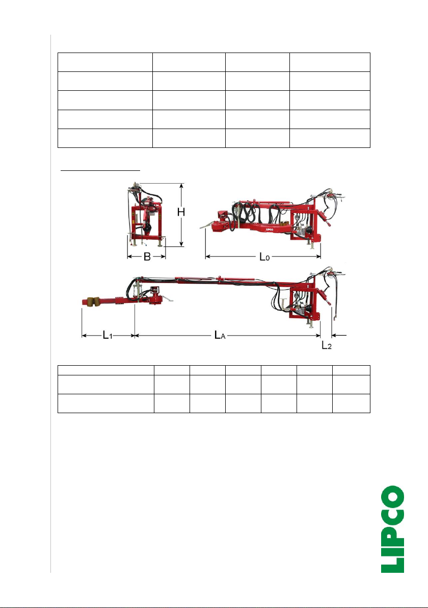
Main dimensions:
L1
L2
LA
L0
H
B
HSA 10 with 2 telescopic
arms
1450
500
4400
3360
1710
1000
HSA 10 with 3 telescopic
arms
1450
500
5400
3540
1710
1000
Instructions
Hydraulic shaker HSA 10
12 - 28
220018-00-EN BA HSA 10 / 28.09.2019
10. Attachment to tractor
•Approach cautiously with the tractor to the back side of HAS 10.
Position lower link.
•Insert mounting bolts through the suspension of the lower link and
secure with linch pin. Tighten lower link.
•Fasten upper link with upper link pin.
•Lift HAS 10 with tractor and move / secure all supports in upper
position.
•Store supports in suitable location for later re-use.
Note !
Lower links of the tractor may only be plugged be-
tween the mounting brackets of the HSA.
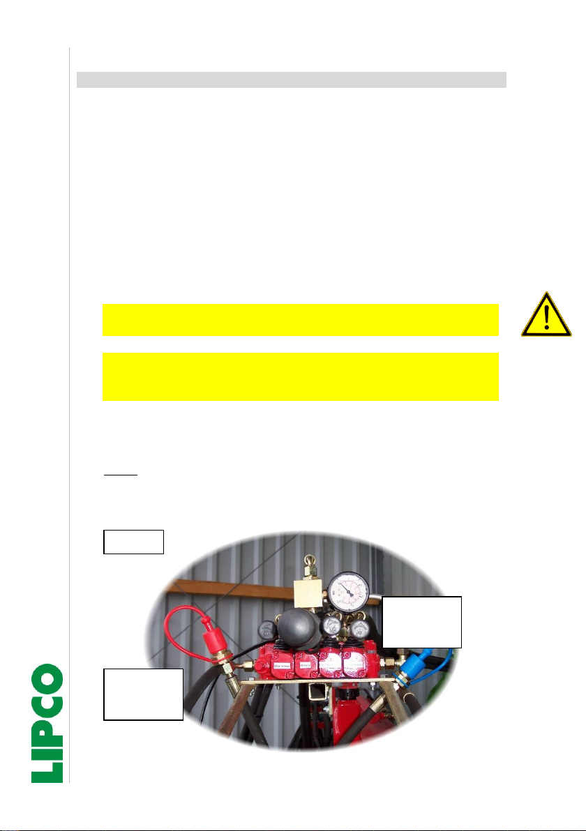
Note !
When connecting the hydraulic lines to the tractor,
make sure that the pressure- and return line (pres-
sure-less) are properly connected. (see Fig. 1)
•Prior to connecting the hydraulic hoses, clean the coupling ele-
ments on tractor- and machine side properly.
•Note:
Any dirt within the hydraulic circuit will damage the sealing of hy-
draulic valves and hydraulic motor.
Fig. 1
Return line
blue protec-
tive cap
Pressure side
red protective
cap

Instructions
Hydraulic shaker HSA 10
13 - 28
220018-00-EN BA HSA 10 / 28.09.2019
Note:
Depending on category (CAT 1 / CAT 2) of tractor
reductions will be required for upper link.
Instructions
Hydraulic shaker HSA 10
14 - 28
220018-00-EN BA HSA 10 / 28.09.2019
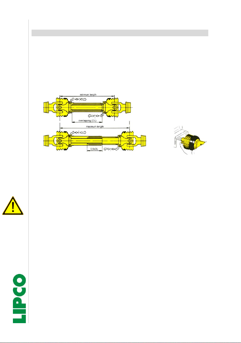
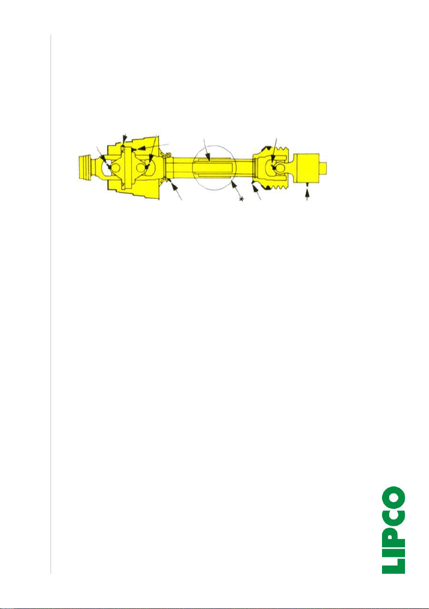
11. Attachment of the universal joint shaft
•Prior to connecting or detaching the universal joint shaft, always
make sure to switch off the power take-off shaft and motor and to
remove the ignition key!
•Press pin and push the universal joint shaft onto the power take-
off shaft until the pin locks into place! (Fig. 2)
Fig. 3
Fig. 2
•After connecting HAS 10 to the tractor, check the length of the
universal joint shaft.
•Note!
Aim for maximum overlap. Minimum overlapping is 0.5xOL = 50%
of maximum overlapping OL. (See Fig. 3)
•When connecting to a different tractor, check the length again!
•When the machine is not in use, locate the universal joint shaft in
the support provided for this purpose.
•When connecting the universal joint shaft to the machine, make
sure that the protective cover covers completely the universal joint
shaft guard in all operating positions!
•For your personal safety, replace damaged or worn protective de-
vices immediately.
Instructions
Hydraulic shaker HSA 10
15 - 28
220018-00-EN BA HSA 10 / 28.09.2019
•Prior to any operation, lubricate universal joint shaft, then following
every 8 hours during operation. Check also free movement!
•During winter season, lubricate protection tubes to avoid freezing.
Locations see lubrication chart. (Fig. 4)
Fig. 4
•Connect safety chains for the universal joint shaft guard so that a
enough swiveling area for the universal joint shaft is possible in all
operating positions. Do not use safety chains for suspending the
universal joint shaft!
•For your personal safety, replace worn or damaged safety parts
immediately.
•Connecting the universal joint shaft to the tractor, check, that the
protection hood on both sides is covering both ends of the univer-
sal joint shaft completely.
•If HAS 10 is not in use, then locate the universal joint shaft in the
adequate hook.
Instructions
Hydraulic shaker HSA 10
16 - 28
220018-00-EN BA HSA 10 / 28.09.2019
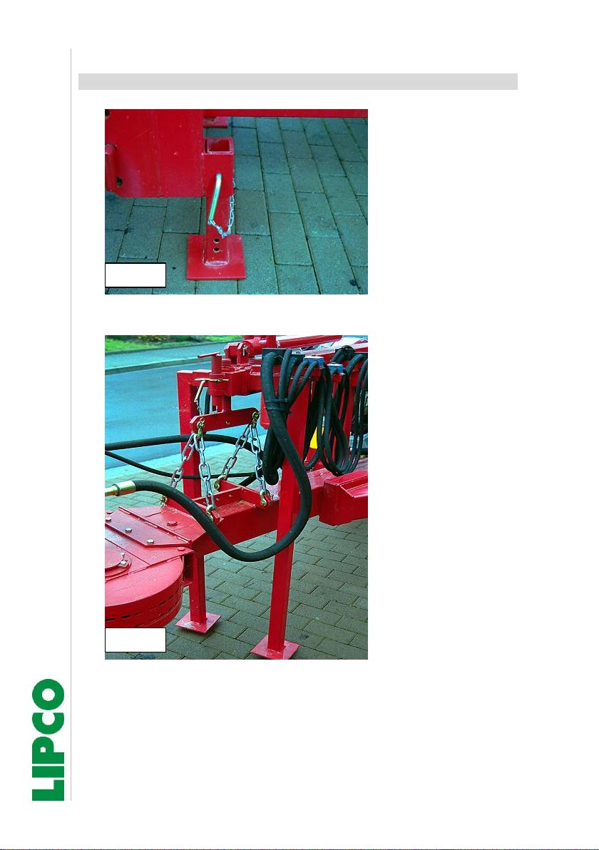
12. Operating HSA 10
•Lift shaker using
tractor hydraulics;
push up the front
parking supports
(Fig. 5) to highest
position and secure
them!
•Remove rear sup-
ports. (Fig. 6)
Fig. 5
Fig. 6
Instructions
Hydraulic shaker HSA 10
17 - 28
220018-00-EN BA HSA 10 / 28.09.2019
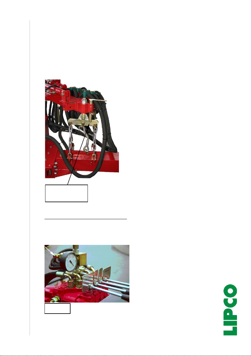
•Set the hydraulic control lever on the tractor to "Pressure".
•Remove transport safety pin.
•On control block of shaker:
Push “Open gripper”
turn the shaker bar manually
by 180° and lock the safety
bolt. The shaker is now ready
for use.
•Move the gripper up to approx.
1.5 m to the trunk and stop.
•Actuate the "Extend" control
lever until the gripper is at the
same level as the trunk.
•Then carefully turn left until the
trunk is in the centre of the grip-
per
•“Close gripper”. Start the
shaking process by switching
on the PTO shaft. Hold control
lever (“Close gripper”) in po-
sition.
•Changing the gripper pressure:
The gripper pressure is factory set to 130 bar. Depending on the
sensitivity of the tree, the pressure can be increased by adjusting
the pressure relief valve (Fig. 7).
Fig. 7
One-man-
handling
Instructions
Hydraulic shaker HSA 10
18 - 28
220018-00-EN BA HSA 10 / 28.09.2019
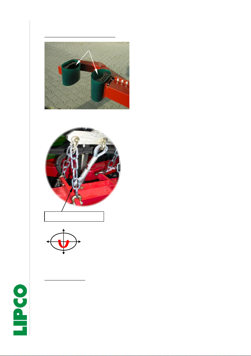
Notes for shaking process:
•In order to avoid damage to
the bark, the shaking rod
must always be placed at
approx. 90° to the trunk or
branch.
•When using the HAS 10, it
is also necessary to lubri-
cate several times a day be-
tween the rubber jaws and
the green rubber band with
a food-safe grease (Vase-
line or milking grease).
•When shaking branches,
the 4 support chains are un-
hooked so that the shaking
rod is held by the wire rope
alone.
•Only short shaking periods:
If the fruits fall badly, repeat
this if necessary or shake
the tree crosswise by swiv-
elling the shaking rod.
•Special edition:
The shaking process is started via an electric on-off valve. For this
special edition, hold control lever (“Close gripper”) also in posi-
tion.
Lubication
Support chains
Shaking directions
Instructions
Hydraulic shaker HSA 10
19 - 28
220018-00-EN BA HSA 10 / 28.09.2019
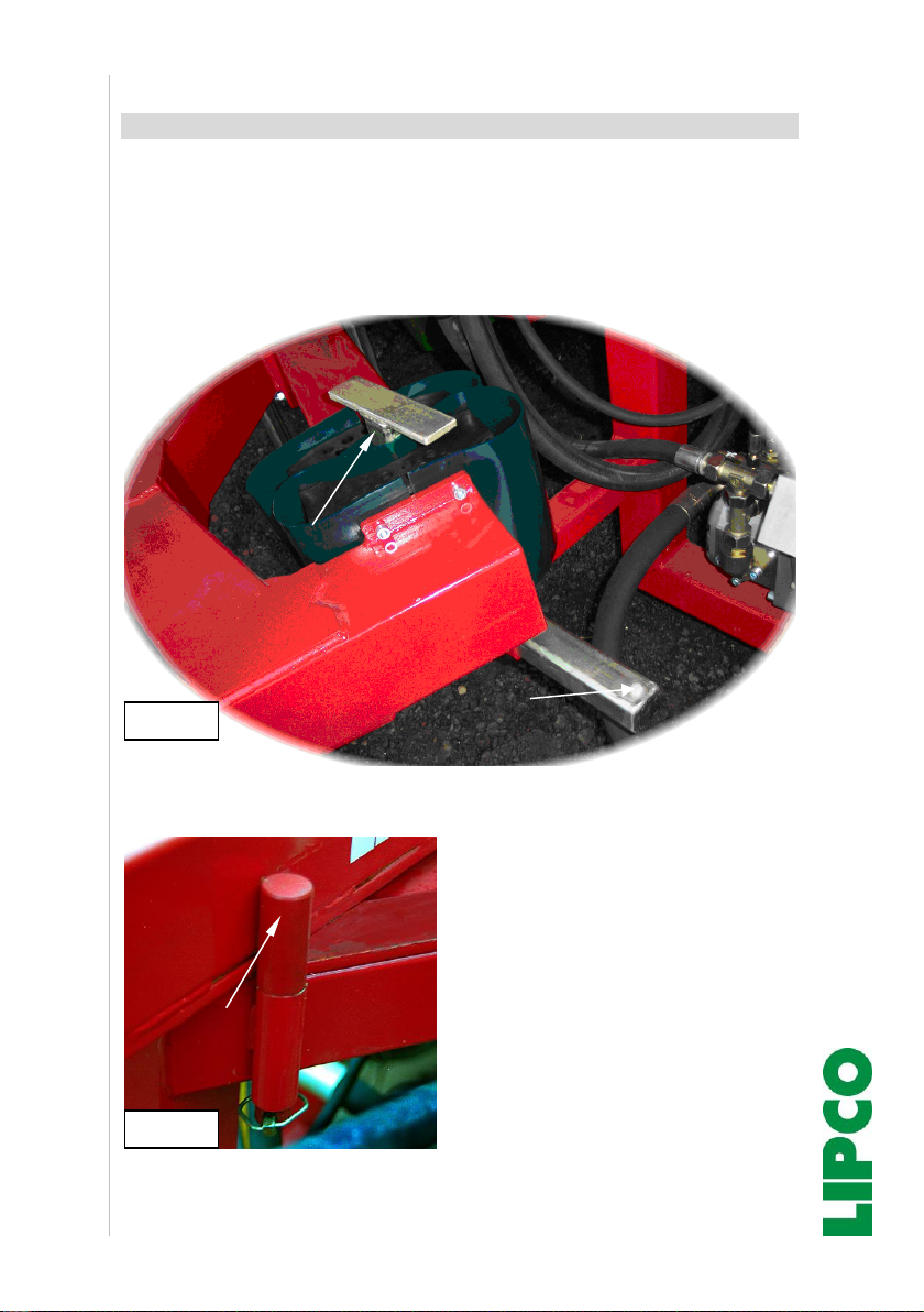
13. Driving on public roads.
When transporting the device on public roads, the shaking rod must
always be fixed in the transport bracket (Fig. 8). The transport locking
bolt (Fig. 9) must also be fitted. All chains must always be hooked in
during transport on public roads.
•The transport bracket is
equipped with a polyamide
screw with a predetermined
breaking point. If the square
tube (transport lock) is pulled
out by incorrect operation,
only the fixed polyamide
screw will be damaged.
•No other screws may be used
as replacements. Only use
the original screw recom-
mended by LIPCO!
Fig. 9
Transport locking
pin
Fig. 8
Transport bracket
Polyamid screw
Instructions
Hydraulic shaker HSA 10
20 - 28
220018-00-EN BA HSA 10 / 28.09.2019
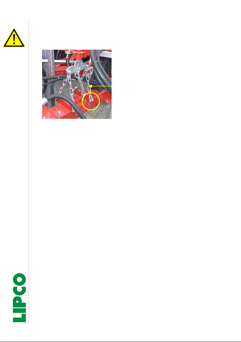
During driving on public roads, all 4 safety chains must always be
hooked in and secured.
Safety chains 4x
Safety pins 6x
Fig. 10
Table of contents
Other Lipco Farm Equipment manuals


