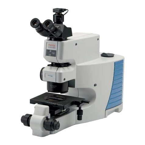
premiere SMZ-05 User manual

STEREO ZOOM MICROSCOPES
Model SMZ-05, Binocular
Model SMZ-07, Trinocular

Contents
1..Before use...................................................................... 3
2..Structure ........................................................................ 4
3..Operation ....................................................................... 5
4..Specifications................................................................. 8
5..Troubleshooting ............................................................. 9

1 B e f o r e u s e
1-1 NOTICE
Thank you for purchasing this Premiere®Stereo Zoom Microscope. For best results
with your instrument, please read this user’s manual thoroughly.
Models SMZ-05 & SMZ-07 Stereo Zoom Microscopes are virtually identical in most
specifications except bottom lighting and SMZ-07 features a third eyepiece tube
which allows a camera attachment (available separately). Unless otherwise noted, the
instructions apply to either version. Details specific to the Trinocular Model SMZ-07
are noted in the instructions.
1) Microscope ought to be placed in a dry and clean place. Do not expose the
microscope to direct sunlight. Avoid high temperature and violent vibration.
2) As microscope is a precision instrument, handle with care, avoiding impact or
abrupt movement during transportation.
3) To keep the image clear, do not leave fingerprints or stains on the surfaces of the
lens.
1-2 GENERAL MAINTENANCE
1) All lenses must be kept clean. Fine dust on the surface of the lens should be blown
off with hand blower or wiped off gently with a soft lens tissue. Fingerprints or oil
should be wiped off with lens paper moistened with a small amount of alcohol.
2) To clean the outer surfaces (especially the plastic surfaces), use only mild
detergent.
3) After use cover the microscope with the dust-cover provided and store it in a clean,
dry place free from moisture.
1-3 UNPACKING
Your microscope is packed in custom fitted protective foam within its cardboard
carton. It is strongly advised to retain all packing materials in the event your
microscope ever needs to be stored or transported. This packaging is designed to
provide the maximum protection when shipping your microscope.

2 S t r u c t u r e
2-1 SMZ-05 Study the diagram to become familiar with the parts of the instrument.
Eyeguards
Eyepiece
Diopter adjusting ring
Head
Illumination
Zoom control knob
Focusing
Lamp lock-screw
Objective lens
Glass stage
Positioning
Knob (on
pole)
Clip Power
cord
socket
Base
Top variable light control
Fuses
Bottom light control
(variable on SMZ-05 only) Power Switch
Figure 1

Figure 1
2-2 ASSEMBLY
1) Remove base with pole from foam packing and place on stable surface (tabletop or
desk) removing all plastic covering. If the head support slides on the pole, tighten the
positioning knob along the back securely to hold it approximately midway on the
pole.
2) You will notice a screw knob fitted into the ring which will hold the head assembly.
Loosen this screw if necessary so that it is flush with the inside of the ring.
3) Fit the head assembly (containing eyetubes and objectives) into the ring and tighten
the screw knob to hold the head in place. Note: this screw knob can be inserted into
any of the three positions as desired to hold the head in place.
4) Insert the illumination device ①in the bracket with the
protrudent side toward the lock-screw②and tighten the
lock-screw into the socket in the illumination device.
(Fig.2)
5) Put the plug into the socket of the pillar stand③.
6) Remove covers from eyetubes and insert eyepieces.
7) Attach the power cord to the socket in the base and plug
in to power supply.
3 O p e r a t i o n
3-1 The glass stage
1) Use the depression in the base to lift the glass stage when
necessary.
2) Setting the clips on the edge of the glass stage plate will help
hold it in place. (Fig.3)
3) Use care to avoid damage to the glass plate.
Figure 3
3-2 Adjust the tension of the focusing mechanism
1) If you want to adjust the tension of the focusing arm, you can
hold one of the focusing knobs and turn the other one to attain a
comfortable setting. The increase or decrease of tension relies on
the direction turned. The clockwise direction is tight,
counter-clockwise is loose.
2) The suitable amount of tension will make the focusing more
comfortable and prevent the focusing bracket from slipping down
by its weight during observation. (Fig.4)
Figure 4
Figure 2
FFigure

3-3 Place the specimen
Note: In general use the user has flexibility with the stand; the head assembly can be raised
or lowered on the pole to accommodate various sized specimens and the entire head
assembly can be rotated 360°on the pole as needed.
1) Set the specimen on the center of stage plate. If necessary, clamp the specimen with the clips.
2) Remove (unscrew) the lens cap over the objective lens.
3) Turn on the power switch located at the back of the base.
4) Using the knob on side of the base, turn on the overhead light.
3-4 Adjust the interpupillary distance
Adjust the eyepiece housing along the direction of arrowhead (Fig.5)
until the eyepieces are a comfortable distance for viewing.
3-5 Adjust the focus
1) Turn the zoom control knob to the maximum magnification
(4.5).
2) Turn the diopter adjusting rings to zero (raised to highest
point).
3) Observe the specimen through the right eyepiece and make
the image clear by turning the focusing knob.
4) Rotate the zoom control knob to the minimum magnification.
5) Observe the specimen through the right eyepiece and make the
image clear by turning the right diopter adjusting ring ②.
(Fig.6)
6) Repeat steps (1), (3), (4) and (5) until the right adjusting ring
is most precise.
7) Repeat step (4) and make the image clear as observed through
the left eyepiece by turning the left diopter adjusting ring ①.
(Fig.6)
Important Model SMZ-07 Trinocular
If no image is visible through the left eyepiece, push in the silver
pole to the left of the head. (Fig. 7)
Once both eyepieces have a clear image in focus, you can adjust
the magnification power as desired without refocusing.
Pole
Figure 7
Figure 6
Figure 5

3-6 Eyepiece guards
1) For user who does not wear glasses, the use of the rubber eyepiece guards will help avoid
glare from any incidental lighting in the room. Fit the rubber eyeguards over the eyepieces
with the deeper edge to the outside of observer’s face.
2) For user who wears glasses, do not install the eyeguards.
3-7 Using Trinocular feature Model SMZ-07
With Model SMZ-07, you can alternate use of the binocular observation with trinocular use of
the third eyetube by installing an eyepiece (not included) or video or digital camera attachment
(sold separately) into the third eyetube. Unscrew the cover from the tube socket and install the
third tube by screwing the tube into place. To obtain the image through this third tube you must
slide out the silver pole to the left of the head. (It is normal for the left eyepiece of the binocular
head to be dark at this point.) Be sure to slide the pole out completely until it stops (approx. ¾”).
(see Fig.7) Refer to manufacturers’ instructions for use of camera with the stereo zoom scope.
3-8 Adjusting the brightness of the lamps
Turn the variable control light knob①according to the sign
marked on the base, turning clockwise to increase the brightness,
counter-clockwise to dim. (Fig.8) Note: Model SMZ-07 is
equipped with a Fluorescent lamp in the bottom light and is not
adjustable.
3-9 Replacing the lamps
Note: Before replacing the lamps, turn off and disconnect the
power.
1) Slide the clips aside and carefully remove the glass stage plate.
(Fig.9)
2) ①Gently remove the lamp from the socket. (Allow a hot bulb to
cool before removing.)
3) Put a new lamp into the socket, be sure it is inserted completely.
Do not touch the new bulb with bare hands as body oils may damage
it.
4) Replace the stage plate. (Fig.10)
3-10 Replacing the fuse
1) Remove the fuse tube with a screwdriver and then pull the fuse
out of the tube ①.(Fig. 11)
2) Replace the fuse and remount it in the fuse holder. (Fig.11)
Figure 9
Figure 10
Figure 11
Figure 8

4 S p e c i f i c a t i o n s
4-1 SMZ-05/SMZ-07
Eyepiece
Standard
configuration
Auxiliary objectives
0.5X
1.5X
2X
Working
distance100mm
Working
distance165mm
Working distance
45mm
Working distance
30mm
Magnification
Field
of
view
Magnification
Field
of
view
Magnification
Field
of
view
Magnification
Field
of
view
10X/20
7X
28.6
3.5X
57.1
10.5X
19
14X
14.3
45X
4.4
22.5X
8.9
67.5X
3
90X
2.2
15X/15
10.5X
21.4
5.25X
42.8
15.75X
14.3
21X
10.7
67.5X
3.3
33.75X
6.7
101.25X
2.2
135X
1.7
20X/10
14X
14.3
7X
28.6
21X
9.5
28X
7.1
90X
2.2
45X
4.4
135X
1.5
180X
1.1
4-2 The base electronic specification of SMZ series
Model
Parts
SMZ-05
SMZ-07
Power supply
110V-50/60Hz, 220V-50Hz
110V-50/60Hz, 220V-50Hz
Transformer
Input: 220/110VAC
Output: 12V DC/45W
Input: 220/110VAC
Output: 12V DC/45W
Illuminator
Top light
12V/15W halogen lamp
12V/15W halogen lamp
Bottom light
12V/15W halogen lamp
7W fluorescent lamp
SMZ-05 & SMZ-07 are equipped with standard 110V and American style 3 prong
plug. Alternate voltage (220V) and plug style is available upon request (special order).

5 Troubleshooting
Trouble
Cause
Remedy
1. Double images
Interpupillary distance is not
correct
Readjust it
Diopter adjustment is not correct
Readjust it
Magnification of each eyepiece
is not the same size
Mount the same size
eyepiece
2. Dirt appears in the field of view
Dirt on the specimen
Clean the specimen
Dirt on the surfaces of eyepiece
Clean the surface
3. Image is not clear
Dirt on the surfaces of the
objectives
Clean the objectives
4. Image is not clear while the focus
changing
Diopter adjustment is not correct
Readjust the diopter
Focus is not correct
Readjust the focus
5. The focusing knob is not smooth
The focusing knob is too tight
Loosen it to a suitable
position
6. The image is obscured because of
the head slipping down by itself
during observation
The focusing knob is too loose
Tighten it to a suitable
position
7. Incision image appears in the field
of view
The pole is not in correct
position
Pull or push it to the
correct position
8. Eyes tire easily
Diopter adjustment is not correct
Adjust the diopter
Brightness of light is not correct
Adjust the brightness
9. Bulb does not work when the
switch is on.
No power supply
Check the connection with
the power supply
The bulb was not inserted
correctly
Insert it correctly
Bulb is wrong
Replace with a new one
10. Bulb is burned out suddenly
Use the wrong bulb
Replace with a correct one
The voltage is too high
Control the voltage
Eg: use voltage regulator
11. Brightness is not enough
Using the wrong bulb
Replace with a correct one
The voltage is too low
Increase the input voltage
12. The bulb flickers or the
brightness is unstable
The bulb will burn out soon
Replace with a new one
The bulb was not inserted
correctly
Insert it correctly

(21/2)
C & A Scientific Co., Inc.
7241 Gabe Court ● Manassas ● Virginia ● 20109
The manufacturer warrants this instrument to be free from defects in material and workmanship
under normal use for five years from the date of purchase (one year for electrical components).
It does not cover damage resulting from abuse or misuse, repairs or alterations performed by
other than authorized repair technicians, or damage occurring in transit. If you have questions
concerning this product or warranty, contact the dealer from whom it was purchased. For
warranty service, microscope should be well packed to avoid damage in transit, preferably in
original box and packing. Include your complete return address and telephone number as well
as a description of the difficulty, date and place of purchase, and ship to the address below. It
will be repaired or replaced at no charge and returned. If misuse, alterations, accident or
abnormal conditions of operation caused failure, an estimate for repairs will be provided for
your approval prior to work being performed.
Premiere®Microscope Service
7241 Gabe Court
Manassas, VA 20109
(703) 330-1413
This manual suits for next models
1
Table of contents
Other premiere Microscope manuals
