Thermo Scientific Nicolet Continuum User manual


Thermo Fisher Scientific Inc. provides this document to its customers with a product purchase
to use in the product operation. This document is copyright protected and any reproduction of
the whole or any part of this document is strictly prohibited, except with the written
authorization of Thermo Fisher Scientific Inc.
The contents of this document are subject to change without notice. All technical information in
this document is for reference purposes only. System configurations and specifications in this
document supersede all previous information received by the purchaser.
Thermo Fisher Scientific Inc. makes no representations that this document is complete, accurate
or error-free and assumes no responsibility and will not be liable for any errors, omissions,
damage or loss that might result from any use of this document, even if the information in the
document is followed properly.
This document is not part of any sales contract between Thermo Fisher Scientific Inc. and a
purchaser. This document shall in no way govern or modify any Terms and Conditions of Sale,
which Terms and Conditions of Sale shall govern all conflicting information between the two
documents.
For U.S. Technical Support, please contact:
Thermo Fisher Scientific
5225 Verona Road
Madison WI 53711-4495 U.S.A.
Telephone: 1 800 532 4752
E-mail: [email protected]
World Wide Web: http://www.thermo.com/spectroscopy
For International Support, please contact:
Thermo Fisher Scientific
Telephone: +1 608 273 5017
E-mail: support.madison@thermofisher.com
World Wide Web: http://www.thermo.com/spectroscopy
© 2000-2011 Thermo Fisher Scientific Inc. All rights reserved.
Adobe and Acrobat are either trademarks or registered trademarks of Adobe Systems, Inc. in the
United States and/or other countries. All other trademarks are the property of Thermo Fisher
Scientific Inc. and its subsidiaries.
269-239701, Rev A

Contents
Nicolet Continuµm Microscopes.............................................................1
Questions and concerns .....................................................................2
About this manual..............................................................................3
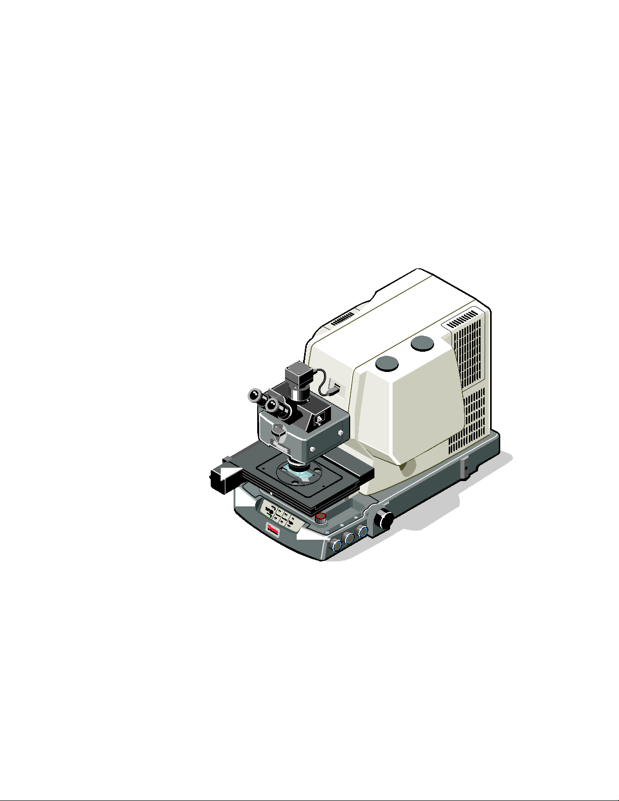
Microscope components ....................................................................4
Preparing the Microscope ........................................................................7
Turning on power...............................................................................7
Cooling the detector.........................................................................11
Installing the purge baffle ................................................................13
Initializing the stage.........................................................................14
Z-axis .........................................................................................15
XY-axes .....................................................................................18
Limiting stage travel ..................................................................22
Controlling stage movement.....................................................25
Preparing the optical components....................................................28
Adjusting the eyepieces .............................................................29
Reticle focus and diopter adjustments .......................................36
Condenser focus and alignment.................................................38
Initializing the Reflex aperture ........................................................43
Analyzing Samples ................................................................................49
Performing a reflection experiment .................................................49
Performing a transmission experiment ............................................63
Advanced Techniques............................................................................77
Polarization options .........................................................................77
Visible polarization....................................................................77
Nomarski differential interference contrast ...............................81
Infrared polarization ..................................................................89
Optical filters ...................................................................................90
Attenuated total reflection ...............................................................91
Setting up the internal Contact Alert System.............................92
Using the internal Contact Alert System .................................100
Setting up the external quantitative Contact Alert System.....108
Grazing angle reflection.................................................................116

More about the Hardware ................................................................... 123
Selecting a detector ....................................................................... 123
Using objectives and condensers .................................................. 127
Specifications and typical uses ............................................... 128
Refractive index compensation............................................... 130
Adjusting field of view and image contrast ................................ 132
Transmission irises.................................................................. 133
Reflection irises ...................................................................... 133
Masking off areas of interest......................................................... 134
Adjusting the aperture size, shape and orientation ................. 135
Using the software to adjust the aperture................................ 136
Using the manual controls to adjust the aperture.................... 138
Using autofocus ............................................................................ 141
Using auto ATR contact................................................................ 145
Troubleshooting .................................................................................. 151
Symptoms and solutions ............................................................... 151
Testing microscope performance.................................................. 168
In reflection mode ................................................................... 168
In transmission mode .............................................................. 176
Upgrading the computer, recovering from viral attacks, and
reinstalling software................................................................ 184
Index ................................................................................................... 187

Continuµm User Guide
1
Nicolet Continuµm Microscopes
Congratulations on your purchase of a Thermo Scientific Nicolet
Continuµm microscope! The Continuµm™ microscope is an
infrared microsampling system that provides the highest available IR
spatial resolution. The Continuµm design enables unlimited
sampling and mapping capability, and incorporates unprecedented
ease of use.
The on-axis infinity corrected optical design of the Continuµm
microscope provides exceptional sample viewing quality and
exceptional infrared sampling.

Thermo Scientific
2
The microscope features the TruView™ illumination system, which
allows continuous optical-quality viewing of the sample. The
Reflex™ aperture minimizes diffraction by using a single aperture to
provide aperturing before and after the sample.
You should be familiar with the operation of your spectrometer and
system software before using the microscope. The microscope was
designed to be used with either OMNIC™ Atlµs™ or OMNIC
software. µView™ software is also available for video management
during visible and discrete point microanalysis. For complete
information on using these packages, see the on-line Help system or
other documentation that came with the software. In this manual, we
will refer to OMNIC Atlµs commands. If your system is not
equipped with OMNIC Atlµs, see the instructions for collecting data
that came with your spectrometer.
The Continuµm microscope must be installed as part of a Thermo
Scientific spectrometer system and can be used only after it is
properly connected to the spectrometer.
The Microscope Safety Guide that came with your microscope
contains important safety information. This guide is available in
several languages. Contact our local office for information about the
languages that are available. To prevent personal injury and damage
to equipment, read the guide and follow the safety precautions
contained in it whenever you use the system.
Questions
and concerns
In case of emergency, follow the procedures established by your
facility. If you have questions or concerns about safety or need
assistance with operation, repairs or replacement parts, you can
contact our sales or service representative in your area or use the
information at the beginning of this document to contact us.

Continuµm User Guide
3
About
this manual
This manual explains how to use the system to collect and process
FT-IR spectra after a Nicolet™ Series spectrometer and Nicolet
Continuµm microscope are installed. Included is basic information
about using OMNIC Atlµs software, as well as chapters on how to
operate the microscope. (If you did not purchase OMNIC Atlµs
software, see the documentation that came with your spectrometer
for information about using OMNIC to collect data.)
A Continuµm microscope is used for illustration purposes. The
following conventions are used in this manual to draw your attention
to important information:
This symbol tells you that you can find more information in the
on-line help and tutorials. To access help or a tutorial, click the Help
menu in OMNIC.
This symbol tells you that you can find more information in this
manual or other printed documentation that came with your
instrument.
Note Notes contain helpful supplementary information.
Notice Follow instructions labeled “Notice” to avoid damaging the system
hardware or losing data.
Caution Indicates a potentially hazardous situation which, if not avoided,
may result in minor or moderate injury. It may also be used to alert
against unsafe practices.
Warning Indicates a potentially hazardous situation which, if not avoided,
could result in death or serious injury.
Danger Indicates an imminently hazardous situation which, if not avoided,
will result in death or serious injury.

Thermo Scientific
4
Microscope
components
The following illustrations identify the microscope controls and
components.

Continuµm User Guide
5
Front panel

Thermo Scientific
6
Control panel (on left side)

Continuµm User Guide
7
Preparing the Microscope
This chapter explains how to prepare a Continuµm microscope for
data collection. It includes information about:
•Turning on the power
•Cooling the detector
•Initializing the microscope stage and, if necessary, limiting stage
travel
•Preparing the optics
Notice The computer and microscope components of your system should
always be powered on before the spectrometer. To ensure that all the
features of your microscope are available, allow at least 20 seconds
to elapse between the time that you power on the computer and
microscope components and powering on the spectrometer.
Turning on power
Always power on the components in your microscope system in the
order that follows.
1. Microscope
2. Stage controller (systems with optional motorized stages only)
4. Illuminators
5. Computer, monitor, printer and other computer peripheral
devices
6. Spectrometer
Notice To ensure that all system components can communicate, be sure that
the microscope has been powered on for at least 20 seconds before
you power on the spectrometer.

Thermo Scientific
8
If you are turning on the microscope for the first time or the
microscope has been off for several hours and you are going to
perform precision mapping experiments, allow one hour following
power on for its temperature to stabilize before continuing. If you are
going to collect routine spectra, the system is ready for use as soon
as you power on.
Before you turn on the microscope power, it is a good idea to verify
that the illuminator controls are in the OFF position. Rotate the
controls counterclockwise until they click into the OFF position.
Then move the power switches to the ON position.
“I” = On
“O” = Off

Continuµm User Guide
9
The power switches are located:
•On the control panel on the left side of the microscope.
•On the front panel of the optional stage controller.
•On the computer, monitor, printer and other peripheral devices.
•On the spectrometer power supply.

Thermo Scientific
10
Once the microscope is powered on, turn on the illuminators and
computer hardware.
•Rotate the illumination controls clockwise to the mid-point.
•For optimum performance, leave the transmission and reflection
illuminators on and set to medium intensity at all times except
when a different intensity is required for viewing.
Finally, turn on the spectrometer power. To ensure that all the
components are recognized, the spectrometer always should be the
last component in a microscope system that is powered on.

Continuµm User Guide
11
Cooling the detector
The microscope is equipped with one or two single-element
detectors. Most of these detectors must be cooled with liquid
nitrogen before use.
Caution Liquid nitrogen is extremely cold and can cause injury. A warm
laboratory dewar, funnel, and detector may cause the liquid nitrogen
to boil rapidly and spatter. When filling the detector dewar, be
careful not to contact the liquid nitrogen with your skin.
Wear protective gloves and splash-proof goggles and follow
precautions described in the material safety data sheets provided by
your liquid nitrogen vendor.
Also note that liquid nitrogen can be hazardous and create an oxygen
deficient atmosphere if handled in an insufficiently ventilated
room.
Detectors that require cooling are encased in a stainless steel dewar.
Once cooled, the detector will remain cold for about 13 hours. You
can add liquid nitrogen as needed at any time except while you are
collecting spectra.
To cool a detector:
1. Fill a laboratory dewar with approximately 750 ml (26 fluid
ounces) of liquid nitrogen.
Less liquid nitrogen may be needed if the detector was cooled
recently.

Thermo Scientific
12
2. Remove the access cover for the detector fill port you wish to
use.
3. Insert the laboratory funnel into the fill port.
The fill ports are offset, toward the front of the access port.
To prevent damage to the microscope internal components, be
sure that the neck of the funnel is inside the fill port. Damage
caused by spilled or misdirected liquid nitrogen is not covered by
warranty.

Continuµm User Guide
13
4. After you have filled the funnel once, allow the detector
dewar to cool for one to two minutes before adding more
liquid nitrogen.
Filling the detector too quickly can cause unnecessary boil off
and hazardous splatter.
5. Continue filling the funnel and allowing the nitrogen to drain
into detector dewar.
The dewar is full when liquid nitrogen no longer drains into it.
6. Allow the detector temperature to stabilize.
For best results, allow the detector to stabilize for at least 20
minutes before analyzing samples.
Installing
the purge baffle
The purge baffle protects the optical components in the microscope
from moisture in your breath. The baffle deflects your breath away
from the polarizer slot when you do not have a polarizer installed.

Thermo Scientific
14
The purge baffle should be installed at all times, unless you have a
polarizer or filter installed in the slot.
Initializing the stage
Both vertical and horizontal movement of optional motorized stages
should be initialized whenever the OMNIC Atlµs or µView
software
is installed, you change computers, and whenever you upgrade or
replace the stage. They also must be initialized any time the
microscope and stage controller are powered off.
Neither manual nor
glide stages require initialization.
Because the stage moves during the automated initialization process,
it is necessary to protect hardware components that could interfere
with the stage’s movement. Prompts that appear during the
initialization ask you to take precautions such as lowering the
condenser or removing the nosepiece.
Note Whenever the OMNIC Atlµs or µView software is installed, you
change computers, and whenever you upgrade or replace the stage,
you also need to calibrate the horizontal movement of the stage.
For more information about calibrating the X-Y movement of the
stage, find “calibrating stage
” in the Atlµs Help system Index and go
to “How to calibrate the stage”.

Continuµm User Guide
15
Z-axis
Whenever the Z-axis of the stage requires initialization, you will see
the message:
when you open the Atlµs window. This message indicates that the
system needs to initialize vertical stage movement to allow accurate
vertical positioning through the software.
Notice Always remove the nosepiece and lower the condenser completely
before you initialize the stage. Stage collision damage is not covered
by warranty.
See “Changing the condenser” and “Changing the objective” in the
“Setting up for experiments” Help book available through
Microscope Help topics in the OMNIC Help menu, if you are
unfamiliar with the procedures for removing and reinstalling the
nosepiece or lowering the condenser.
To initialize the Z-axis:
1. Remove the nose piece and lower the condenser completely.

Thermo Scientific
16
2. Choose System Configuration from the Atlµs menu in
OMNIC.
3. Click the Z-Axis button in the Microscope field.
Table of contents
Other Thermo Scientific Microscope manuals