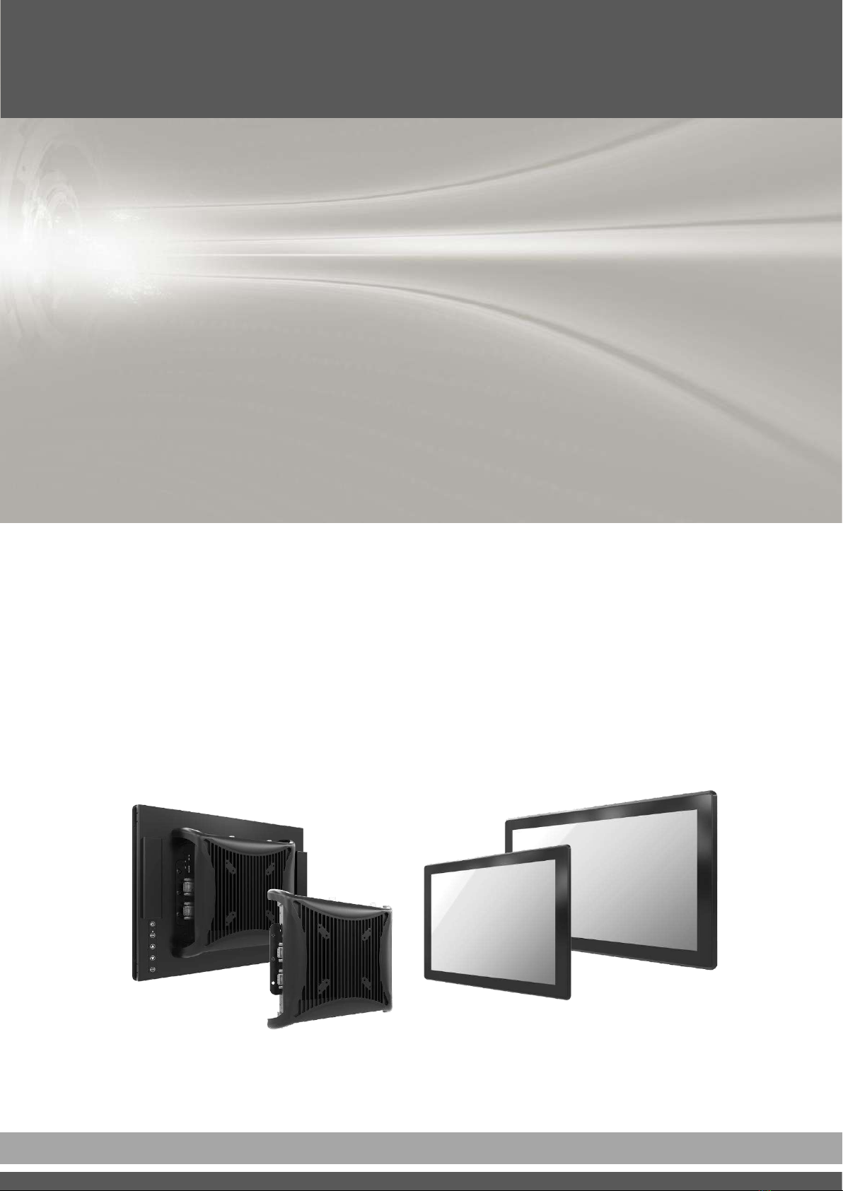
VIO-PC100-EHL lUser’s Manual
Table of Contents
2
Prefaces …………………………………………………….……………………………………………. 04
Revision …………………………………………………………………………………………..……………….……….. 04
Disclaimer ………………………………………………………..…….…….………………………….……………….. 04
Copyright Notice …………………………………….…………………….…………………………………………… 04
Trademarks Acknowledgment …………..………………………………………………………...................04
Environmental Protection Announcement …………………………….………………….……………….. 04
Safety Precautions ………………………………………….……………………………….…………….………….. 05
Technical Support and Assistance …………………………………….…………….…………….…………….06
Conventions Used in this Manual ………………………………………………………………….….………..06
Package Contents …………………………………………………………………………………………….…………07
Ordering Information …………………………………….……………………………………….……….………… 08
Optional Accessory …………...……………………………………..................................................... 10
Chapter 1 Product Introductions ………………………………………………………..… 11
1.1 Overview ……………………….………………………………..………….………………..……….. 12
Key Feature ………….……………………………………….……….…..………..…................ 12
1.2 Hardware Specification ….………………………….....…………….…………..…..………… 13
1.3 System I/O ……………………………..……………………..…………………………………..…… 17
1.3.1 PC100-EHL ………………………………….......................................……….…… 17
1.3.2 PC100-EHL-1E ……………………………..…………………………………..…………... 19
1.3.3 VESA Mounting Hole …………………..…………………………………..…………... 21
1.4 Mechanical Dimension …………………………..…………………………..………….………. 22
1.4.1 VIO-212-PC100-EHL Series ……………..…….………………..…………............. 22
1.4.2 VIO-215-PC100-EHL Series ……………..…….………………..…………............. 23
1.4.3 VIO-217-PC100-EHL Series ……………..…….………………..…………............. 24
1.4.4 VIO-219-PC100-EHL Series ……………..…….………………..…………............. 25
1.4.5 VIO-W215-PC100-EHL Series ……………..….………………..…………............ 26
1.4.6 VIO-W221-PC100-EHL Series ……………..…………………..…………............. 27
1.4.7 VIO-W224-PC100-EHL Series ……………..…….…..………..…………............. 28
Chapter 2 Switches and Connectors ……..…………………………………………..…. 29
2.1 Switch and Connector Locations ……………………………………..…….…..……..….... 30
2.1.1 Top View ……………………………………………………………………....……………… 30
2.1.2 Bottom View ……………………………………………………………………....……….. 31
2.2 Connector / Switch Definition ……………………………….……….…….………............ 32
Chapter 3 Front Panel Controls ……..……………………………………….………..…. 47
3.1 Users Controls ……………………………………..…….…..……..……………………..……….. 48
3.2 OSD Operation ……………………………….……….…….………................................... 49
3.2.1 Luminance …………………………………………………………………....……………… 49
3.2.2 Picture …………………………………………………………………………..…....……….. 49
3.2.3 Color …………………………………………………………....………………………………. 50
3.2.4 OSD Settings .………………………………………………………………..…....……….. 50
3.2.5 Setup …………………………………………………………………………..…....………….. 50
Chapter 4 System Setup ……………………..………………………………………..……… 51
4.1 Set torque force to 3.5 kgf-cm to execute all the screwing and unscrewing. 52
4.2 Installing SODIMM …………………………………………………………………………………... 52
4.3 Installing mini PCIe card / mSATA / M.2 E Key ……………….……..…………………. 53