Premium Products CBW10 General instructions

FILL IN FOR FUTURE REFERENCE
MODEL NO:___________________________________________
DATE INSTALLED:______________________________________
DEALER:______________________________________________
INSTALLATION, OPERATION, AND
MAINTENANCE MANUAL
CBW10, CBW10D, CBW20, CBW20D
CCF10, CCF10D, CCF20, CCF20D
(Addendum Included)
AUTOMATIC WATER
FILTERS
PP0131
0611
Supersedes
0610
SPECIFICATION TABLE
Units CBW10,
CBW10D
CCF10,
CCF10D
CBW20,
CBW20D
CCF20,
CCF20D
Service Flow (1) Cont. GPM 3 3 5 5
Peak GPM 8 8 10 10
Pipe Size In/Out - Inches 1” 1” 1” 1”
Operating Pressure Range PSI 30 - 125 30 - 125 30 - 125 30 - 125
Max Operating Temperature Degrees F 110 110 110 110
Mineral Tank Size (Dia. x Ht.) (2) Inches 10 x 44 10 x 44 12 x 52 12 x 52
Shipping Weight Lbs. 47.5 137 57.5 235
Overall Height Inches 52 52 60 60
Drain Flow During Regeneration(3) GPM 5.3 6.5 7.5 7.5
NOTE:
(1) Pressure drop not to exceed 15 psi.
(2) Product materials and workmanship are protected with a written warranty.
(3) Untreated water provided during all steps of regeneration.
023367

2
remier
remier
roducts
roducts
P
P
P
P
WATER TREATMENT
®Automatic Water Filters
Filter Tank
Assembly
Sanitary Drain, Floor Drain or
Laundry Tubs are acceptable.
Do not make a direct connection
to the drain. An air gap must
be present.
Cold filtered water inlet
30 p.s.i. minimum pressure
1” minimum pipe size
Maximum drain pipe
elevation above drain
port is 5 ft.
High Pressure Warning:
If feedwater pressure is known to be above
125 psi, it is strongly recommended that a
pressure reducing valve be installed at this point.
Unfiltered water to Sprinklers and any
dersired unfiltered fixtures
Ground Strap
Filter Water Outlet
Manual Outlet Valve
(optional)
110-125 Volt
Continuous Power Supply
Transformer
Manual Bypass Valve
(Normally Closed)
(optional)
Manual Inlet Valve
(optional)
Drain Port
Drain line 1/2” ID diameter
minimum size
Connection to sanitary sewer line
(optional)
Air gap device
Sanitary sewer line
Drain Trap
Drain
IL1037
Typical Water CBW Installation

3
remier
remier
roducts
roducts
P
P
P
P
WATER TREATMENT
®Automatic Water Filters
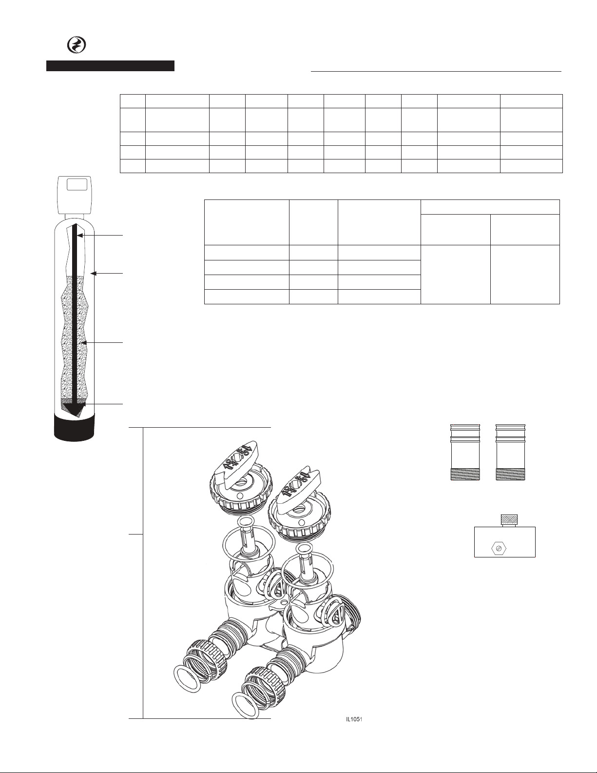
INSTALLATION FITTING ASSEMBLIES
Installation fittings connect to the control valve or the
bypass valve using nuts that only require hand tightening.
Hand tight nut connections between control valve and
installation fittings, control valve and bypass valve, and
bypass valve and installation fittings allow for ease
serviceability. Do not use a pipe wrench to tighten nuts
on installation fittings. Hand tighten only.
Split ring retainer design holds the nut on and allows load
to be spread over the entire nut surface area reducing the
chance for leakage. The split ring design, incorporated
into the installation fittings allows approximately 2
degrees off axis alignment to the plumbing system. The
installation fittings are designed to accommodate minor
plumbing misalignments but are not designed to support
the weight of a system or the plumbing.
When assembling the installation fitting package,
connect the fitting to the plumbing system first and then
attach the nut, split ring and o-ring. Heat from soldering
or solvent cements may damage the nut, split ring or
o-ring. Solder joints should be cool and solvent cements
should be set before installing the nut, split ring and
o-ring. Avoid getting primer and solvent cements on any
part of the o-rings or split rings, bypass valve or control
valve. Solvent cements and primers should be used in
accordance with the manufacturer’s instructions.
Slip the nut onto the fitting first, then the split ring
second and the o-ring last. hand tighten the nut. If the
fitting is leaking, tightening the nut will not stop the
leak. Remove the nut, remove the fitting, and check for
damage or misalignment of the o-ring.
Do not use pipe dope or other sealant on threads. Teflon
tape must be used on the threads of the 1” connection
and on the threads for the drain line connection. Teflon
tape is not necessary on the nut connection or caps
because of o-ring seals.
Do not use Vaseline, oils or other unacceptable lubricants
on o-rings. A silicon lubricant may be used on black
o-rings.
BYPASS VALVE
The bypass valve easily connects to the control valve
body using nuts that only require hand tightening. Hand
tighten nut connections between control valve and
fittings, control valve and bypass valve, and bypass valve
and installation fittings allow for easy serviceability. The
split ring retainer design holds the nut on and allows load
to be spread over the entire nut surface area reducing the
chance for leakage. The split ring design, incorporated
into the bypass, allows approximately 2 degrees off axis
alignment to the plumbing system. The bypass is designed
to accommodate minor plumbing misalignments but is
not designed to support the weight of a system or the
plumbing.
Avoid getting primer and solvent cements on any part
of the o-rings or split rings, bypass valve or control valve.
Do not use pipe dope or other sealant on threads. Teflon
tape is not necessary on the caps because of o-ring seals.
Do not use Vaseline, oil or other unacceptable lubricants
on o-rings. A silicon lubricant may be used on black
o-rings.
A. GENERAL
1. Shut off all water at main supply valve.
2. Shut off the fuel supply to water heater.
3. Open faucets (hot and cold) nearest pump or water
meter to relieve pressure and drain system.
4. Move filter into the installation position. Loosely
attach all fittings to measure for bypass valve
assembly (if used), or manual bypass valve.
5. Level the unit. (Do Not use metal shims.)
6. Cut the cold water supply line as required.
7. Install the bypass valve assembly if used.
B. PLANNING INSTALLATION
1. All installation procedures must conform to local
plumbing, electrical and sanitation codes and
ordinances.
2. It is recommended that outside faucets for lawn
service be on the hard water line, ahead of the filter,
to conserve filtered water.
3. If this isn’t practical, use the convenient integral
bypass valve assembly.
CAUTION: The inlet water temperature MUST NOT
exceed 120° F.
4. Do not locate filter where ambient temperature
drops below 40° F.
5. Allow space around the filter for ease of servicing.
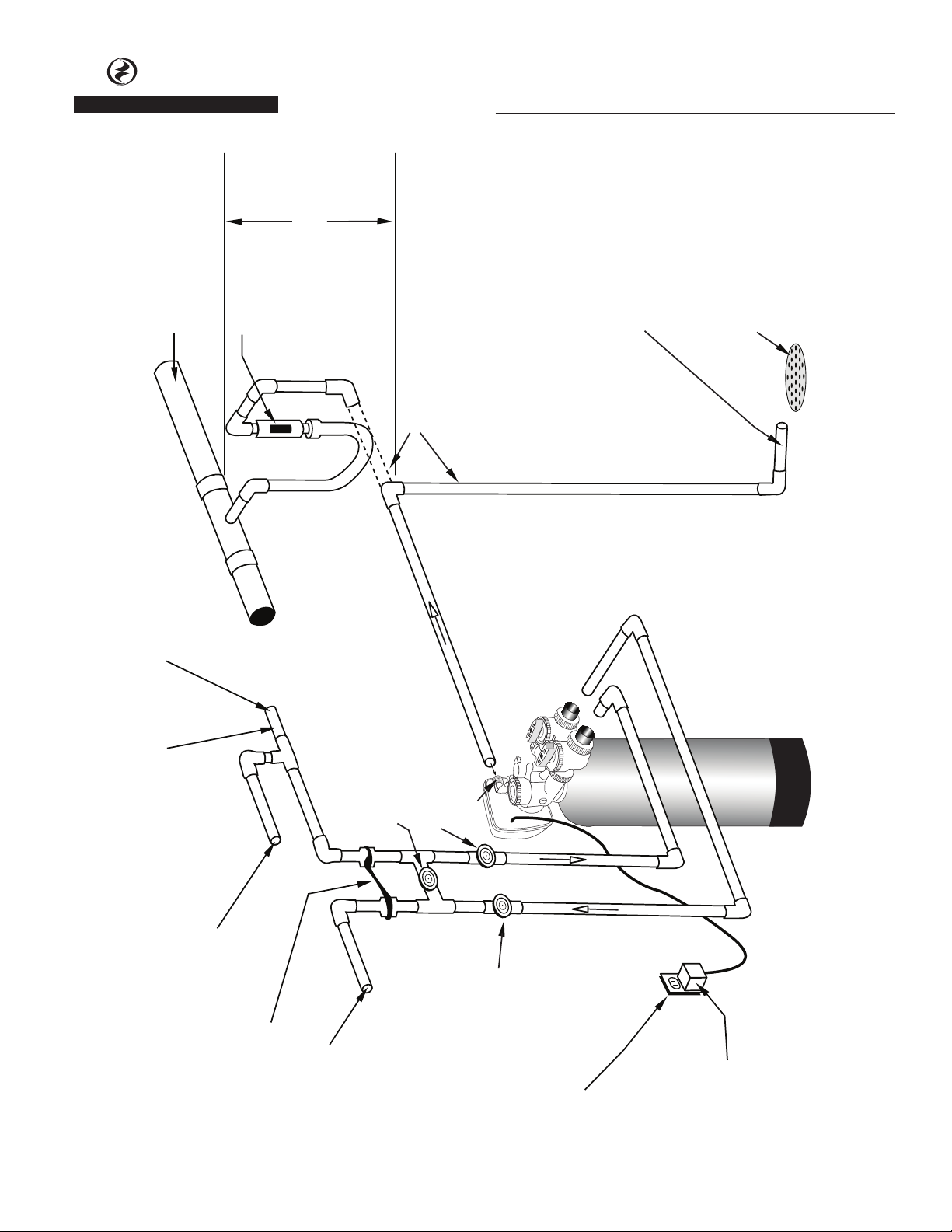
6. The filter drain lines must never be solidly connected
to the sewer line. (Always provide an air gap at the
END of the drain line). Valve drain line must not be
elevated over 5’ from the top of the filter on well
systems, and not over 8’ on municipal water systems.
7. Move the filter into position and connect to bypass
assembly (if used). The integral manual bypass option
is a connection which eliminates the need for a
3-valve manifold. This makes installation easier and
provides a more convenient method of bypassing.
8. IMPORTANT: Be sure that the water inlet line is
connected to the “inlet” side of the bypass valve or
to the inlet fitting. (Bypass valve both inlet/outlet
fittings are marked.) If water lines are reverse, (inlet/
outlet) filter mineral may be forced from the water
filter into the household plumbing system. If this

4
remier
remier
roducts
roducts
P
P
P
P
WATER TREATMENT
®Automatic Water Filters
occurs, household plumbing system must be flushed
clean.
C. CONNECT ALL FITTINGS
(refer to previous page)
CAUTION: Care must be used when working with copper
tubing. Do not allow the flame from torch to contact any
portion of the Valve assembly.
1. Attach 3/4” drain line to drain elbow with insert and
nut.
2. Do not elevate the drain line over 5’ above the top of
the valve (8’ on municipal systems) or to exceed 25’ in
length at either height.
CAUTION: An air gap must be provided upon sewer
entry. (Conform to local plumbing and sanitation
codes and ordinances).
1. Media was shipped boxed under media tank.
Carefully unscrew control valve. Be sure to “plug” the
top of the distributor tube using tape or some other
means. Do not allow filter media to enter inside of
distributor tube. (See Fig. 3)
2. Pour the separately boxed media into media tank.
3. Lubricate o-rings on control valve with silicone
lubricant. DO NOT USE PETROLEUM JELLY.
4. Lubricate bypass valve o-rings with silicone lubricant
and secure to the control valve using adapter
couplings, clips and screws.
5. Cut main supply line as required to fit plumbing to
the inlet and outlet of bypass valve. Make certain
water flow enters through the Inlet and discharges
through the Outlet of the bypass valve.
6. Attach drain line to drain line fitting. Position drain
line over drain and secure firmly. To prevent back
siphoning, be sure to have adequate air gap of at
least 2 inches.
7. Make certain bypass valve is in the “bypass” position.
Turn on power to well pump or open main supply
valve completely.
8. Plug control valve into a non-switched 115v power
source.
9. Manually stage filter to the backwash position (see
service manual).
10. Open inlet valve and allow the unit to fill SLOWLY.
This will allow air to escape from the media tank.
Once water continually flows to drain, open both
inlet and outlet valves fully.
11. Check for leaks and allow filter to backwash for at
least 10 minutes or until water flowing from drain
runs clear.
12. Allow unit to fully regenerate (see service manual).
13. Models CBW10D, CBW20D, CCF10D and CCF20D have
a dome hole/plug located in the upper dome of the
mineral tank. This is used to replenish mineral as
required. DO NOT remove dome hole plug without
first depressurizing the tank.
Distributor Tube
Media Tank
Filter Media
Gravel - preinstalled
Dome Hole (”D” suffix models only)
INSPECTION AND HANDLING YOUR FILTER
Be sure to inspect the equipment for shipping damage
and notify the transportation company if damage exists.
Handle the filter with care, as damage can result if
dropped or if the filter is set on a sharp object.
CONDUCT A THOROUGH WATER TEST
Your water should have a thorough analysis prior to the
selection of water conditioning equipment. Enter your
analysis below:
WATER ANALYSIS
IRON (fe) __________ ppm
Manganese (Mn) __________ ppm
pH __________
Tannins __________ ppm
Hydrogen Sulfide (H2S) __________ ppm
NOTE: Hydrogen Sulfide must be tested at the well site.
Failure to conduct an “on site” analysis will result in
inaccurate test results.
LOCATING EQUIPMENT CORRECTLY
The location of your filter should be selected carefully. A
variety of conditions will contribute to proper location as
follows:
1. Locate as close as possible to the source of water
supply.
2. Locate as close as possible to drain, i.e. laundry tub or
floor drain.

5
remier
remier
roducts
roducts
P
P
P
P
WATER TREATMENT
®Automatic Water Filters
3. Locate in correct relationship to other water
treatment equipment (See Figure 1).
4. Allow sufficient area around the equipment for
service.
FACTS TO REMEMBER WHILE PLANNING
YOUR INSTALLATION
1. All installation procedures MUST conform to local and
state plumbing codes.
2. If lawn sprinkling, a swimming pool or geothermal
heating/cooling are to be treated by the Chemical
Free filter, a larger model filter MUST be selected to
accommodate the higher flow rate demands.
3. IMPORTANT: Always use Teflon tape on threaded
plastic fittings. NEVER use pipe dope, as it will
deteriorate the plastic fittings.
CHECK WATER PRESSURE
Minimum water pressure required at the inlet of the
filter is 20 psi. IF PRESSURE IS OVER 100 PSI, A PRESSURE
REGULATING VALVE MUST BE INSTALLED TO REDUCE
WATER PRESSURE.
NOTE: Pressure regulating valve must be installed in
water line ahead of the air induction assembly.
CHECK PUMPING RATE OF WELL PUMP
The pumping rate of your well pump must be sufficient
to properly backwash the filter. Check backwash flow rate
required for specific filter model.
Water Pressure Low _____ psi
High _____ psi
Pumping Rate _________ GPM
Figure 1 - Standard Installation
FILTERED WATER
FILTERED
SO FT WATER
WATER
SO FTE NER
WATER
FILTER
PRESSURE
TANK
PRESSURE
SWITCH
WELL WATER
FROM PUMP
IL1039

6
remier
remier
roducts
roducts
P
P
P
P
WATER TREATMENT
®Addendum for CCF Series
Automatic Water Filters Only
BEFORE INSTALLING YOUR FILTER
INSPECTION AND HANDLING YOUR FILTER
Be sure to inspect the equipment for shipping damage
and notify the transportation company if damage exists.
Handle the filter with care, as damage can result if
dropped or if the filter is set on a sharp object.
CONDUCT A THOROUGH WATER TEST
Your water should have a thorough analysis prior to the
selection of water conditioning equipment. Enter your
analysis below:
WATER ANALYSIS
IRON (fe) __________ ppm
Manganese (Mn) __________ ppm
pH __________
Tannins __________ ppm
Hydrogen Sulfide (H2S) __________ ppm
NOTE: Hydrogen Sulfide must be tested at the well site.
Failure to conduct an “on site” analysis will result in
inaccurate test results.
LOCATING EQUIPMENT CORRECTLY
The location of your filter should be selected carefully. A
variety of conditions will contribute to proper location as
follows:
1. Locate as close as possible to the source of water
supply.
2. Locate as close as possible to drain, i.e. laundry tub or
floor drain.
3. Locate in correct relationship to other water
treatment equipment (See Figure 1).
4. Allow sufficient area around the equipment for
service.
FACTS TO REMEMBER WHILE
PLANNING YOUR INSTALLATION
1. All installation procedures MUST conform
to local and state plumbing codes.
2. All water MUST pass through the air
induction assembly, pressure tank and
the Chemical-Free Iron Filter (See Figure
1)
3. If lawn sprinkling, a swimming pool or
geothermal heating/cooling are to be
treated by the Chemical Free filter, a
larger model filter MUST be selected
to accommodate the higher flow rate
demands.
4. IMPORTANT: Always use Teflon tape on threaded
plastic fittings. NEVER use pipe dope, as it will
deteriorate the plastic fittings.
CHECK WATER PRESSURE
Minimum water pressure required at the inlet of the
filter is 30 psi. IF PRESSURE IS OVER 125 PSI, A PRESSURE
REGULATING VALVE MUST E INSTALLED TO REDUCE
WATER PRESSURE.
NOTE: Pressure regulating valve must be installed in
water line ahead of the air induction assembly.
CHECK PUMPING RATE OF WELL PUMP
The pumping rate of your well pump must be sufficient
to properly backwash the filter. Check backwash flow rate
required for specific filter model.
Water Pressure Low _____ PSI
High _____ PSI
Pumping Rate _________ GPM
INSTALLATION
INSTALLING THE AIR INDUCTION ASSEMBLY
1. Shut off all water at the main supply. On a private
well system, turn off power to the pump and drain
pressure tank. Make sure pressure is relieved from
complete system by opening nearest faucet to drain
system. SHUT OFF FUEL SUPPLY TO WATER HEATER.
2. Cut main supply line as required to fit air induction
assembly in plumbing between well pump and
pressure tank. Air induction assembly may be installed
in a vertical or horizontal position. Position air
induction assembly so that the flow adjusting screw
is accessible for adjustment by screwdriver. Install
unions to facilitate air induction assembly removal
and inspection. Be certain the Flow Arrow on air
induction assembly points toward the pressure tank
Figure 1 - Standard Installation
IRON FREE WATER
IRON FREE
SO FT WATER
WATE R
SO FTE NER
WATER
FILTER
PRESSURE
TANK
PRESSURE
SWITCH
AIR INDUCTION
ASSEMBLY
WELL WATER
FROM PUMP
IL1040

7
remier
remier
roducts
roducts
P
P
P
P
WATER TREATMENT
®Addendum for CCF Series
Automatic Water Filters Only
and pressure control switch is located on pressure
tank side of the air induction assembly (See Figure
2). Allow 8” of straight pipe on both sides of air
induction assembly.
WATER FLOW WATER FLOW
FLOW ADJUSTING SCREW
SUCTION
PORT
IL1041
Figure 2 - Air Induction Assembly
INSTALLING THE FILTER
1. Media was shipped separately. Carefully unscrew
the control valve. Be sure to “plug” the top of the
distributor tube using tape or some other means. Do
not allow filter media to enter inside of distributor
tube (See Figure 3).
Distributor Tube
Media Tank
Filter Media
Gravel - preinstalled
Dome Hole (”D” suffix models only)
Figure 3 - Media Tank Cutaway
2. Pour the separately shipped media into media tank.
3. Replace control valve on media tank. Lubricate
o-rings on control valve with silicone lubricant. DO
NOT USE PETROLEUM JELLY.
4. Lubricate bypass valve o-rings with silicone lubricant
and secure to the control valve using adapter
couplings, clips and screws.
5. Cut main supply line as required to fit plumbing to
the inlet and outlet of bypass valve. Make certain
water flow enters through the Inlet and discharges
through the Outlet of bypass valve.
6. Attach drain line to drain line fitting. Position drain
line over drain and secure firmly. To prevent back
siphoning, be sure to have adequate air gap of at
least 2 inches.
7. Make certain bypass valve is in the “bypass” position.
Turn on power to well pump or open main supply
valve completely.
8. Plug control valve into a non-switched 115V power
source.
9. Manually stage filter to the backwash position (see
service manual).
10. Open inlet valve and allow the unit to fill SLOWLY.
This will allow air to escape from the media tank.
Once water continually flows to drain, open both
inlet and outlet valves fully.
11. Check for leaks and allow filter to backwash for at
least 10 minutes, or until water flowing from drain
runs clear.
12. Allow unit to fully regenerate (see service manual).
13. Models CCF10D and CCF20D have a dome hole/plug
located in the upper dome of the mineral tank. This
is used to replenish mineral as required. DO NOT
remove dome hole plug without first depressurizing
the tank.
ADJUSTING THE AIR INDUCTION ASSEMBLY
1. Open nearest faucet until pump starts, then close
faucet.
2. Place finger lightly over SUCTION PORT (See figure 2).
A slight suction should be detected for approximately
ONE-THIRD of pumping cycle. (Do not confuse with
one-third of PRESSURE RANGE).
3. If suction duration is too short, increase by turning
FLOW ADJUSTING SCREW CLOCKWISE. To decrease
duration, turn COUNTER CLOCKWISE.
4. Repeat steps 1 through 3 until proper setting is
obtained.
NOTE: When the duration of the suction is too long, cold
water may have a “milky” appearance caused by excess
air in the system. Correct this condition by reducing the
duration of suction. This condition is commonly associated
with bladder type pressure tanks In extreme cases where
elimination of excess air prevents system from performing
satisfactorily, it may be necessary to install a standard air-
to-water type pressure tank with an air relief valve.
WATER FLOW WATER FLOW
FLOW ADJUSTING SCREW
SUCTION
PORT
IL1041
Figure 2

8
remier
remier
roducts
roducts
P
P
P
P
WATER TREATMENT
®Automatic Water Filters
D. PRESSURE TEST THE INSTALLATION
The plumbing system can now be checked for any
possible leaks
1. Open the water supply inlet valve very slowly. Once
the mineral tank is full of water, slowly open the
outlet on the bypass. Open a faucet down stream
from the filter & allow the air to escape. DO NOT
INITIATE A BACKWASH UNTIL MEDIA IS SATURATED.
2. Allow water to run until clear. CHECK FOR LEAKS!
3. Plug the unit in.
4. Make sure the power cord is plugged into a properly
grounded wall receptacle.
E. PROGRAMMING THE CONTROL VALVE
How To Set Time Of Day
The user can set the time of day. Time of day should only
need to be set initially, and after extended power outages
or when daylight saving time begins or ends and at the
time of start-up. If an extended power outage occurs, the
time of day will flash on and off which indicates the time
of day should be reset.
STEP 1U - press
SET
HOUR
.
STEP 2U - Current Time (hour):
Set the hour of the day using
or buttons. AM/PM toggles
after 12.
STEP 3U - press
SET
HOUR
button to
complete and return to display
mode.
How To Change Time of Backwash and Days
Between Backwashes
STEP 1 - From normal mode,
press
SET
HOUR &buttons
simultaneously for 3 seconds and
release.
STEP 1A - Backwash Time:
Set the clock to the hour the
backwash should occur by using the and
buttons. An arrow will point to p.m. after 12 (factory
default is 1 a.m.). Press
SET
HOUR
to go to step 1B.
STEP 1B - Setting Days Between Backwash:
Use the and buttons to set the days between
backwashes (factory default is 3 days).
Press
SET
HOUR
to return to Normal mode.
Backwash Mode
Typically a system is set to backwash at a time of low
water usage. An example of a time with low water usage
is when a household is asleep. If there is a demand for
water when the system is backwashing, untreated water
will be used.
When the system begins to backwash, the display will
change to include information about the step of the
backwash process. The system runs through the steps
automatically and will reset itself to provide treated
water when the backwash has been completed.
Manual Backwash
Sometimes there is a need to
backwash the system, sooner than
when the system calls for it, usually
referred to as manual backwash.
To initiate a manual backwash at
the preset delayed backwash time,
press and release and
simultaneously. An arrow point on
the display indicates that the system
will backwash at the preset delayed backwash time. If you
pressed the and buttons in error, pressing the
buttons again will cancel the request.
To initiate a manual backwash immediately, press and
hold the and buttons simultaneously for four
seconds. The system will begin to backwash immediately.
The request cannot be cancelled. You can manually step
through individual cycles by pressing the button until
display reaches normal mode.
Power Loss
If the power goes out for less than two hours, the system
will automatically reset itself. If an extended power
outage occurs, the time of day will flash on and off which
indicates the time of day should be reset. The system will
retain the other information entered by your plumbing
professional.
SET
HOUR
REGEN
MIN. FILL
REGEN
HOUR
TIME-HOUR
PM
DAYS TO
REGEN
3
OR
SET
HOUR
REGEN
MIN. FILL
REGEN
HOUR
TIME-HOUR
PM
DAYS TO
REGEN
1
IL1042
SET
HOUR
REGEN
MIN. FILL
REGEN
HOUR
TIME-HOUR
PM
DAYS TO
REGEN
3
IL1075
SET
HOUR
REGEN
MIN. FILL
REGEN
HOUR
TIME-HOUR
PM
DAYS TO
REGEN
3
OR
IL1074
SET
HOUR
REGEN
MIN. FILL
REGEN
HOUR
TIME-HOUR
PM
DAYS TO
REGEN
3
IL1075

9
remier
remier
roducts
roducts
P
P
P
P
WATER TREATMENT
®Automatic Water Filters
IL1043 IL1044
IL1045
DIAGNOSTIC MODE
Supply
Water Exits
Supply
Water Enters
Figure 3
Diagnostic:
The inlet handle points in the direction of flow and the outlet handle
points to the center of bypass valve, system water pressure is allowed
to the control valve and the plumbing system while not allowing
water to exit from the control valve to the plumbing.
BYPASS OPERATION
IL1046
No
Water Exits
Supply Water is shut off
from the house and the
valve
SHUT OFF MODE
Figure 4
Shut Off:
The inlet handle points to the center of the bypass valve and the
outlet handle points in the direction of flow, the water is shut off to
the plumbing system. If water is available on the outlet side of the
softener it is an indication of water bypass around the system (i.e. a
plumbing connection somewhere in the building bypasses the system).
“Untreated”
Water Exits
Supply
Water Enters
Figure 2
Bypass:
The inlet and outlet handles point to the center of the bypass, the
control valve is isolated from the water pressure contained in the
plumbing system. Untreated water is supplied to the plumbing
system.
NORMAL OPERATION
“Treated”
Water Exits
Supply
Water Enters
Figure 1
Normal Operation:
The inlet and outlet handles point in the direction of flow indicated
by the engraved arrows on the control valve. Water flows through
the control valve during normal operation and this position also al-
lows the control valve to isolate the media bed during the regenera-
tion cycle.
Bypass Valve
The bypass valve is typically used to isolate the control
valve from the plumbing system’s water pressure in order
to perform control valve repairs or maintenance. The
bypass valve is particularly unique in the water treatment
industry due to its versatility and state of the art design
features. The bypass valve incorporates four positions
including a diagnostic position that allows service
personal to work on a pressurized system while still
providing untreated bypass water to the facility or
residence. Its completely non-metallic, all plastic, design
allows for easy
access and serviceability without the need for tools.
The bypass body and rotors are glass filled Noryl and the
nuts and caps are glass filled polypropylene. All seals are
self-lubricating EPDM to help prevent valve seizing after
long periods of non-use. Internal o-rings can easily be
replaced
if service is required.
The bypass consists of two interchangeable plug valves
that are operated independently by red arrow shaped
handles. The handles identify the flow direction of the
water. The plug valves enable the bypass valve to operate
in four positions.

10
remier
remier
roducts
roducts
P
P
P
P
WATER TREATMENT
®Automatic Water Filters
IL1047
Service Tool
7
Turn counter-clockwise to remove.
Turn clockwise to install.
Item
No.
Part
No.
Description Qty
1 023406 Motor 1
2 023412 PC Board 1
3 023408 Piston Assy. 1
4 023409 Seal Assy. 1
5 023410 O-Ring Kit 1
6 127001 Mineral Fill Funnel 1
7 023362 Service Tool 1
8 023411 Transformer 110V-12V 1
IL1049
Funnel
IL1061
Transformer
6
8

11
remier
remier
roducts
roducts
P
P
P
P
WATER TREATMENT
®Automatic Water Filters
1
2
3
4
Application* Part # Description
Qty
CBW10
CBW10D
CBW20
CBW20D
Iron Removal 135514 Birm
1 Box
1 CF
2 Boxes
2 CF
Acid Neutralizer 023357 Calcite
Sediment 135518 Filter-AG
Taste & Odor 135516 Activated Carbon
Bypass Valve Less
Connectors
023328
Connectors
023329
Set of 2
IL1052
Air Inducer
CCF10 Only
021708
IL1053
Item Description CBW10 CBW10D CBW20 CBW20D CCF10 CCF10D CCF20 CCF20D
1Distributor
tube / screen 023360 023360 023488 023488 023360 023360 023488 023488
2 Mineral tank 023319 023320 023483 023491 023319 023320 023483 023491
3 Mineral * * * * 023358 023358 023358(Qty 2) 023358(Qty 2)
4 Gravel 135523 135523 023529 023529 135523 135523 023529 023529

12
remier
remier
roducts
roducts
P
P
P
P
WATER TREATMENT
®Automatic Water Filters
Table 6 - Troubleshooting Procedures
Problem Possible Cause Solution
1. Timer does not
display time of day
a. AC adapter unplugged a. Connect power
b. No electric power at outlet b. Repair outlet or use working outlet
c. Defective transformer c. Replace transformer
d. Defective PC board d. Replace PC board
2. Timer does not
display correct time
of day
a. Switched outlet a. Use uninterrupted outlet
b. Power outage b. Reset time of day
c. Defective PC board c. Replace PC board
3. Control valve
regenerates at
wrong time of day
a. Power outages a. Reset control valve to correct time of day
b. Time of day not set correctly b. Reset to correct time of day
c. Defective PC board c. Reset regeneration time
4. E1, E2, or E3
E1 - Unable to recognize
start of regeneration
E2 - Unexpected stall
E3 - Motor ran too
long, timed out trying
to reach the next cycle
position or trying to
reach home position
a. Control valve has just been serviced a. Press SET HOUR and DOWN for 3 seconds or
unplug power source jack (black wire) from
the circuit board and plug back in to reset
control valve.
b. Foreign matter is lodged in control valve b. Check piston and spacer stack
assembly for foreign matter.
c. High drive forces on piston c. Replace piston(s) and spacer stack assembly
d. Control valve piston not in home position
d. Press SET HOUR and DOWN for 3 seconds or
unplug power source jack (black wire) from
the circuit board and plug back in to reset
control valve
e. Motor not inserted fully to engage pinion,
motor wires broken or disconnected, motor
failure
e. Check motor and wiring. Replace
motor if necessary
f. Drive gear label dirty or damaged, missing
or broken gear
f. Clean drive gear
g. Drive bracket incorrectly aligned to back
plate
g. Reseat drive bracket properly
h. PC board is damaged or defective h. Replace PC board
i. PC board incorrectly aligned to drive
bracket
i. Ensure PC board is correctly snapped on to
drive bracket
5. Control valve stalled
in regeneration
a. Motor not operating a. Replace motor
b. No electric power at outlet b. Repair outlet or use working outlet
c. Defective AC adapter c. Replace AC adapter
d. Defective PC board d. Replace PC board
e. Broken drive gear or drive cap assembly e. Replace piston kit
f. Broken piston retainer f. Replace piston kit
g. Broken main or regenerant piston g. Replace piston kit
7. Control valve does
not regenerate
automatically when
UP and DOWN
button is depressed
and held
a. AC adapter unplugged a. Connect AC adapter
b. No electric power at outlet b. Repair outlet or use working outlet
c. Broken drive gear or drive cap assembly c. Replace drive gear or drive cap assembly.
d. Defective PC board d. Replace PC board
8. Control valve does
lnot regenerate
automatically but
does when UP and
DOWN button is
depressed and held
a. Defective PC board a. Replace PC board
b. Set-up error b. Check control valve set-up procedure
This manual suits for next models
7
Table of contents
Popular Water Filtration System manuals by other brands

Atlantic Ultraviolet
Atlantic Ultraviolet MIN-6 owner's manual

Steinbach
Steinbach Speed Clean Classic 310 ORIGINAL OWNER'S MANUAL

TATA Swach
TATA Swach Ultima Silver RO user manual

Espa
Espa FLIBT12 instruction manual

Proeco
Proeco Bio Flow 5000 instruction manual

Panasonic
Panasonic TK-AS45 instruction manual

Rockford Fosgate
Rockford Fosgate RLS-1815 Owner's maintenance guide/INSTALLATION INSTRUCTIONS

Sicce
Sicce Tidal 55 owner's manual

EverWave Filtration
EverWave Filtration EVW-AZR-4RO manual

Pall
Pall Versalon G410 Series Service instructions

AQUAPHOR
AQUAPHOR RO-101S owner's manual

AMI
AMI AAA-ROPH-50 Manual for installation, operation & maintenance