PrePRESS PANTHER PRO/46 User manual

PantherPro/46 Image Recorder TP8251
iOctober 1995 PrePRESS SOLUTIONS CONFIDENTIAL
Table of Contents
Section 1 General Service Information Page
1-1 Scope of Manual . . . . . . . . . . . . . . . . . . . . . . . . . . . . . . . . . . . . . . . . . . 1-1
1-2 Laser Information . . . . . . . . . . . . . . . . . . . . . . . . . . . . . . . . . . . . . . . . . . 1-2
1-3 Regulatory Agencies Information. . . . . . . . . . . . . . . . . . . . . . . . . . . . . . 1-3
1-4 Electrostatic Discharge - ESD . . . . . . . . . . . . . . . . . . . . . . . . . . . . . . . . 1-4
Section 2 Overview and Specifications
2-1 System Overview . . . . . . . . . . . . . . . . . . . . . . . . . . . . . . . . . . . . . . . . . . 2-1
2-2 Hardware Overview . . . . . . . . . . . . . . . . . . . . . . . . . . . . . . . . . . . . . . . . 2-2
2-3 Electrical Power Requirements . . . . . . . . . . . . . . . . . . . . . . . . . . . . . . . 2-9
2-4 Product Specifications . . . . . . . . . . . . . . . . . . . . . . . . . . . . . . . . . . . . . 2-10
Section 3 Theory of Operation
3-1 PantherPro/46 Image Recorder Overview. . . . . . . . . . . . . . . . . . . . . . . 3-1
3-2 Big Output Board (BOB) . . . . . . . . . . . . . . . . . . . . . . . . . . . . . . . . . . . . 3-3
3-3 High Speed Laser Amplifier (HSLA) PCB . . . . . . . . . . . . . . . . . . . . . . 3-11
3-4 High Speed Laset Driver PCB/Laser Tube Assmbly . . . . . . . . . . . . . . 3-12
3-5 Graphics LCD/Keypad Assembly and Backlight Inverter PCB . . . . . . 3-13
3-6 Media Transport .. . . . . . . . . . . . . . . . . . . . . . . . . . . . . . . . . . . . . . . . . 3-13
3-7 Optical System. . . . . . . . . . . . . . . . . . . . . . . . . . . . . . . . . . . . . . . . . . . 3-18
3-8 Sensors and Switches . . . . . . . . . . . . . . . . . . . . . . . . . . . . . . . . . . . . . 3-20
Section 4 Power Supply and Distribution
4-1 AC Power. . . . . . . . . . . . . . . . . . . . . . . . . . . . . . . . . . . . . . . . . . . . . . . . 4-1
4-2 DC Power. . . . . . . . . . . . . . . . . . . . . . . . . . . . . . . . . . . . . . . . . . . . . . . . 4-3
Section 5 Installation
5-1 Bill of Materials. . . . . . . . . . . . . . . . . . . . . . . . . . . . . . . . . . . . . . . . . . . . 5-1
5-2 Pre-Installation Procedure . . . . . . . . . . . . . . . . . . . . . . . . . . . . . . . . . . . 5-1
5-3 Electrical Requirements . . . . . . . . . . . . . . . . . . . . . . . . . . . . . . . . . . . . . 5-1
5-4 Installation Procedure . . . . . . . . . . . . . . . . . . . . . . . . . . . . . . . . . . . . . . 5-2
5-5 System Test . . . . . . . . . . . . . . . . . . . . . . . . . . . . . . . . . . . . . . . . . . . . . . 5-3
5-6 Installation Completion. . . . . . . . . . . . . . . . . . . . . . . . . . . . . . . . . . . . . . 5-4

PantherPro/46 Image Recorder
ii October 1995
TP8251
PrePRESS SOLUTIONS CONFIDENTIAL
Section 6 Maintenance Page
6-1 Periodic Maintenance . . . . . . . . . . . . . . . . . . . . . . . . . . . . . . . . . . . . . . 6-1
6-2 Optics Cleaning Procedures . . . . . . . . . . . . . . . . . . . . . . . . . . . . . . . . . 6-1
6-3 Adjustable Clutch . . . . . . . . . . . . . . . . . . . . . . . . . . . . . . . . . . . . . . . . . 6-6
6-4 Safety Considerations . . . . . . . . . . . . . . . . . . . . . . . . . . . . . . . . . . . . . 6-9
Section 7 Removal/Replacement Page
7-1 External Covers and Panels . . . . . . . . . . . . . . . . . . . . . . . . . . . . . . . . . 7-1
7-2 Page Buffer Module(s) . . . . . . . . . . . . . . . . . . . . . . . . . . . . . . . . . . . . . . 7-5
7-3 Big OutPut Board/Wide Controller PCB. . . . . . . . . . . . . . . . . . . . . . . . . 7-5
7-4 Page Buffer (PB) Disk Drives. . . . . . . . . . . . . . . . . . . . . . . . . . . . . . . . . 7-6
7-5 LCD and Terminator PCB . . . . . . . . . . . . . . . . . . . . . . . . . . . . . . . . . . . 7-6
7-6 LCD Inverter PCB . . . . . . . . . . . . . . . . . . . . . . . . . . . . . . . . . . . . . . . . . 7-6
7-7 Polygon Driver PCB/Motor Assembly . . . . . . . . . . . . . . . . . . . . . . . . . . 7-7
7-8 Zenith ZPS-300 Power Supply. . . . . . . . . . . . . . . . . . . . . . . . . . . . . . . . 7-7
7-9 Condor Power Supply . . . . . . . . . . . . . . . . . . . . . . . . . . . . . . . . . . . . . . 7-8
7-10 Cooling Fan Assembly . . . . . . . . . . . . . . . . . . . . . . . . . . . . . . . . . . . . . . 7-8
7-11 High Speed Laser Amplifier PCB. . . . . . . . . . . . . . . . . . . . . . . . . . . . . . 7-8
7-12 Laser Fan (Retrofit Kit) Assembly . . . . . . . . . . . . . . . . . . . . . . . . . . . . . 7-8
7-13 Start Of Line Amplifier/Sensor PCB . . . . . . . . . . . . . . . . . . . . . . . . . . . . 7-9
7-14 High Speed Lased Driver/Laser Tube Assembly. . . . . . . . . . . . . . . . . . 7-9
7-15 Second Cylinder Lens Assembly . . . . . . . . . . . . . . . . . . . . . . . . . . . . . 7-10
7-16 Scan Lens . . . . . . . . . . . . . . . . . . . . . . . . . . . . . . . . . . . . . . . . . . . . . . 7-12
7-17 Gate Assembly. . . . . . . . . . . . . . . . . . . . . . . . . . . . . . . . . . . . . . . . . . . 7-13
7-18 Drag-Pinch Roller. . . . . . . . . . . . . . . . . . . . . . . . . . . . . . . . . . . . . . . . . 7-14
7-19 Drive Pinch Roller . . . . . . . . . . . . . . . . . . . . . . . . . . . . . . . . . . . . . . . . 7-15
7-20 Gate Media Out Switch . . . . . . . . . . . . . . . . . . . . . . . . . . . . . . . . . . . . 7-15
7-21 Gate Punch Motor Home Switch . . . . . . . . . . . . . . . . . . . . . . . . . . . . . 7-15
7-22 Adjustable Clutch . . . . . . . . . . . . . . . . . . . . . . . . . . . . . . . . . . . . . . . . . 7-16
7-23 Drag Roller. . . . . . . . . . . . . . . . . . . . . . . . . . . . . . . . . . . . . . . . . . . . . . 7-17
7-24 Drive Roller . . . . . . . . . . . . . . . . . . . . . . . . . . . . . . . . . . . . . . . . . . . . . 7-18
7-25 Knife Motor Assembly . . . . . . . . . . . . . . . . . . . . . . . . . . . . . . . . . . . . . 7-18
7-26 Knife Carriage Assembly . . . . . . . . . . . . . . . . . . . . . . . . . . . . . . . . . . . 7-19
7-27 Worm Gearbox Assembly . . . . . . . . . . . . . . . . . . . . . . . . . . . . . . . . . . 7-19
7-28 Leading Worm . . . . . . . . . . . . . . . . . . . . . . . . . . . . . . . . . . . . . . . . . . . 7-19
7-29 Servo Leading Motor/Encoder Assembly. . . . . . . . . . . . . . . . . . . . . . . 7-20
7-30 Leading Spur Gear . . . . . . . . . . . . . . . . . . . . . . . . . . . . . . . . . . . . . . . 7-20

PantherPro/46 Image Recorder TP8251
iiiOctober 1995 PrePRESS SOLUTIONS CONFIDENTIAL
Section 8 Referenve/Adjustments Page
8-1 Component Locations . . . . . . . . . . . . . . . . . . . . . . . . . . . . . . . . . . . . . . 8-1
8-2 PCB Reference/Adjustments(Jumpers, LEDs, Switches, etc. ). . . . . . . 8-2
8-3 Page Buffer Disk Drive Jumpers . . . . . . . . . . . . . . . . . . . . . . . . . . . . . 8-10
8-4 Power Supply Jumpers/Adjustments . . . . . . . . . . . . . . . . . . . . . . . . . . 8-11
8-5 Take-up Cassette. . . . . . . . . . . . . . . . . . . . . . . . . . . . . . . . . . . . . . . . . 8-13
8-6 Supply Cassette. . . . . . . . . . . . . . . . . . . . . . . . . . . . . . . . . . . . . . . . . . 8-13
8-7 Clutch. . . . . . . . . . . . . . . . . . . . . . . . . . . . . . . . . . . . . . . . . . . . . . . . . . 8-15
8-8 Line Length and Leading . . . . . . . . . . . . . . . . . . . . . . . . . . . . . . . . . . . 8-16
8-9 Margin . . . . . . . . . . . . . . . . . . . . . . . . . . . . . . . . . . . . . . . . . . . . . . . . . 8-16
Section 9 Diagnostics
9-1 Panther Pro Software Overview (Pro Downloader) . . . . . . . . . . . . . . . . 9-1
9-2 PantherPro/46 Diagnostics Overview . . . . . . . . . . . . . . . . . . . . . . . . . . 9-6
9-3 PROM Resident Diagnostics . . . . . . . . . . . . . . . . . . . . . . . . . . . . . . . . . 9-9
9-4 Disk Resident Diagnostics (Debug Port) . . . . . . . . . . . . . . . . . . . . . . . 9-14
9-5 Front Panel Menu System . . . . . . . . . . . . . . . . . . . . . . . . . . . . . . . . . . 9-23
Section 10 Parts Listing
Explanatory . . . . . . . . . . . . . . . . . . . . . . . . . . . . . . . . . . . . . . . . . . . . . 10-2
Group 1 Covers, Doors, and Panels . . . . . . . . . . . . . . . . . . . . . . . . . . . . . . . . . 10-3
Group 2 Electronics Chassis . . . . . . . . . . . . . . . . . . . . . . . . . . . . . . . . . . . . . . . 10-6
Group 3 Optical Base Components . . . . . . . . . . . . . . . . . . . . . . . . . . . . . . . . . . 10-8
Group 4 Media Feed Transport . . . . . . . . . . . . . . . . . . . . . . . . . . . . . . . . . . . . 10-10
Group 5 Paper Feed Transport Drive . . . . . . . . . . . . . . . . . . . . . . . . . . . . . . . 10-14
Group 6 Cables and Harnesses. . . . . . . . . . . . . . . . . . . . . . . . . . . . . . . . . . . . 10-16
Group 7 Supply Cassette. . . . . . . . . . . . . . . . . . . . . . . . . . . . . . . . . . . . . . . . . 10-21
Group 8 Take-up Cassettes. . . . . . . . . . . . . . . . . . . . . . . . . . . . . . . . . . . . . . . 10-24

PantherPro/46 Image Recorder
iv October 1995
TP8251
PrePRESS SOLUTIONS CONFIDENTIAL

PantherPro/46 Image Recorder TP8251
vOctober 1995 PrePRESS SOLUTIONS CONFIDENTIAL
TP8251
October 1995
PrePRESS SOLUTIONS CONFIDENTIAL
2
PantherPro/46
Image Recorder
TECHNICAL MANUAL
PreliminaryPreliminary

PantherPro/46 Image Recorder TP8251
October 1995 PrePRESS SOLUTIONS CONFIDENTIAL 1-1
Section 1 General Service Information
1-1 Scope of Manual
The "PantherPro/46 Image Recorder Technical Manual" is intended for the use of trained
technical representatives of PrePRESS Solutions Inc., its subsidiaries and dealers. It is not
intended as a substitute for training. Service personnel will utilize this document as a
resource for information to maintain the high imaging quality and performance of the
recorder.
Section 1: “General Service Information”, contains general information regarding the
technical manual, laser safety information, regulatory agencies information, and
electro-static discharge prevention rules.
Section 2: “Overview and Specifications”, contains a system overview and performance
specifications of the PantherPro/46 Imagesetting System.
Section 3: “Theory of Operation”, describes in detail the functionality of the PantherPro/46
image recorder.
Section 4: "Power Supply and Distribution", contains details regarding the AC and DC
power distribution of the PantherPro/46 image recorder.
Section 5: “Installation”, contains the installation instructions for the PantherPro/46
Imagesetting System.
Section 6: "Maintenance" contains the maintenance procedures for the PantherPro/46
image recorder.
Section 7: “Removal/Replacement”, contains removal/replacement procedures for field
serviceable electronic, optical, and mechanical components contained in the
PantherPro/46 image recorder.
Section 8: “Reference/Adjustments, contains reference material and adjustment
procedures for the PantherPro/46 image recorder that are useful in diagnosing
error conditions.
Section 9: “Diagnostics”, contains an overview of the PantherPro Software, Debug Port,
and Bomb Messages. Diagnostic test procedures normally performed on the
PantherPro/46 image recorder are also contained in this section.
Section 10: “Parts Listing”, contains a catalog which identifies part numbers of
the PantherPro/46 image recorder.

TP8251 PantherPro/46 Image Recorder
1-2 PrePRESS SOLUTIONS CONFIDENTIAL October 1995
1-2 Laser Safety Information
CAUTION - Use of controls or adjustments or performance of procedures other than
those specified herein may result in hazardous radiation exposure.
Classification and Labeling of Laser Product
According to the Code of Federal Regulations, laser products are classified in Classes I
through IV. These classes are assigned according to the amount of laser radiation accessible
to the operator. The PantherPro/46 Image Recorder is certified as a Class I product. The
operator is not exposed to any hazardous laser radiation during operation and maintenance.
The laser itself, however, is a Class IIIb laser, and emits laser radiation which is considered
hazardous according to the Federal Code of Regulations, section 1040.10. This level of
radiation is not accessible to the operator as long as the optics cover of the Panther Pro/46 is
not removed.
The PantherPro/46 uses a low-power, 5 milliwatt laser diode which emits visible red light. As
with any bright source of optical energy, safety precautions should be applied. One should
not stare into the beam or any reflections from shiny sources.
Laser Warning Labels
Figure 1-1 represents the laser warning label. This label is located inside the Panther Pro/46
on a protective panel that encloses the laser optics and on the rear panel.
CAUTION - LASER RADIATION WHEN OPEN.
AVOID DIRECT EXPOSURE TO BEAM.
ATTENTION - RAYONNEMENT LASER EN CAS
D’OUVERTURE. EXPOSITION DANGEREUSE AU FAISCEAU
Safety Label
Figure 1-1
Operator Safety
Operator access to laser radiation is not possible during operation or operator maintenance.
During operation the protective housing prevents access to all radiation fields. The recorder
hinged supply cassette cover may safely be opened for operator maintenance. This
maintenance includes removing and installing the photographic media supply and take-up
cassettes.
To insure safety during maintenance, redundant interlocks shut off power to the laser diode
assembly (laser diode power up to 5 milliwatts at 670 nanometers could be accessible in the
machine interior if the interlocks are defeated). The Panther Pro/46 electronics and optics
covers should never be removed by the customer.
Servicing Safety
Service procedures include removal of the machine covers to replace or adjust components.
The inner laser assembly and other components may be replaced in the field. The laser
output and the focused beam are accessible in the interior.

PantherPro/46 Image Recorder TP8251
October 1995 PrePRESS SOLUTIONS CONFIDENTIAL 1-3
The supply cassette cover includes two magnetic interlock switches which are mounted and
connected in series so that if the access door is lifted, both switches open to open the
interlock circuit. When the interlock circuit is open, all power is dropped to the current source
for the laser diode.
All service procedures will be performed with the main power shut off and with the safety
interlock circuit open (no laser diode current).
When performing alignments, carefully follow the procedures documented in the technical
manual. DO NOT defeat the safety interlock switches unless specified in the procedure. Also,
NEVER override the safety interlock switches if the polygon/motor assembly is not spinning,
as this could allow the focused beam to be emitted.
Caution: Direct or indirect reflected eye contact with the laser beam may cause serious
eye damage.
Warning: At no time should the unit be left unattended with the interlocks defeated.
The following safety precautions should always be observed:
1. Never operate the unit with the optics cover removed.
2. Laser safety goggles must be worn when making any adjustments to the recorder with the
interlocks defeated.
3. Any adjustments that are to be made with the interlocks defeated must be made in a
secure area, with only trained personnel present.
4. Do not place screwdrivers or other shiny objects in the path of the laser beam.
5. Remove all jewelry from fingers and wrists before making any alignments.
6. Remember that the laser beam may cause permanent damage to the eyes.
1-3 Regulatory Agencies Information
The PantherPro/46 is an approved product designed and manufactured in accordance with
UL (Underwriters Laboratories) and CSA (Canadian Standards Association) standards. The
product also complies with the requirements in Part 15 of FCC Rules for a Class A computing
device.
This equipment complies with the requirements in part 15 of FCC Rules for a Class A
computing device. Operation of this equipment in a residential area may cause unacceptable
interference to radio and TV reception requiring the operator to take whatever steps are
necessary to correct the interference.
The PantherPro/46 image recorder also complies with specific European safety standards;
International models are shipped with a label bearing the “CE” mark. This label demonstrates
compliance with IEC safety standards. The PantherPro/46 also meets EN55022/VDE Class B

TP8251 PantherPro/46 Image Recorder
1-4 PrePRESS SOLUTIONS CONFIDENTIAL October 1995
emissions standards.
1-4 Electrostatic Discharge - ESD
Static electricity is, simply, electricity that is not moving. It is harmless as long as it remains
static. Unfortunately, an electrical charge is unstable and is always looking for an opposite
charge to unite with. When a charge moves, it becomes a current, which is often greater than
a electronic circuit can handle.
The smallest static charge that can be felt is 3,000 volts; the smallest charge that can be seen
is 5,000 volts; and the smallest charge that can be heard is 10,000 volts. Some
semiconductor devices are susceptible to a static charge as little as 10 volts.
Electrostatic discharge has become more and more of a hazard as microcircuit components
have become smaller and more sensitive.
ESD Prevention Rules
These are the rules to be learned and followed in order to prevent ESD damage to electronic
printed circuit boards and assemblies.
1. Always use the antistatic portable field service kit when working near exposed electronic
parts or when handling printed circuit boards.
2. Make sure machine is plugged in a grounded outlet (and switched off) if using the
machine frame as a grounding point.
3. Make sure your wrist strap and antistatic service kit are connected together and
connected to ground.
4. When replacing printed circuit boards, remove the old board from the machine before
removing replacement board from the antistatic bag. Then install replacement board and
place old board in the antistatic bag.
5. Always transport and store electronic components in an antistatic bag.
6. Use the correct size bag, not too big or not too small.
7. Keep antistatic bags in good condition. Bags with pin holes, rips, tears, or crumpled bags
are less efficient and may provide little or no protection.
8. Do not remove components from bags just to look at them. You can usually see through
the bag to identify the part.
9. Keep spare bags on hand.
10. Always ship back field returns in an antistatic bag. Even defective components should be
stored and transported in antistatic bags so that they are not damaged further.
11. Keep static producing materials such as polyester, plastic, and Styrofoam away from
electronic parts.

PantherPro/46 Image Recorder TP8251
October 1995 PrePRESS SOLUTIONS CONFIDENTIAL 1-5
12. Don’t pick up boards unless you are grounded or the boards are in antistatic bags. Do
not touch edge connectors on PCB’s, or exposed circuitry. Handle IC’s, and boards by
the edges, and never place components on metal surfaces.
13. Static is present at all times, more so when the humidity is low.
14. Educate customers about static protection, especially the ones who maintain their own
equipment.
PanthePro/46 Image Recorder TP8251
October 1995 PrePRESS SOLUITIONS CONFIDENTIAL 2-1
Section 2 Overview and Specifications
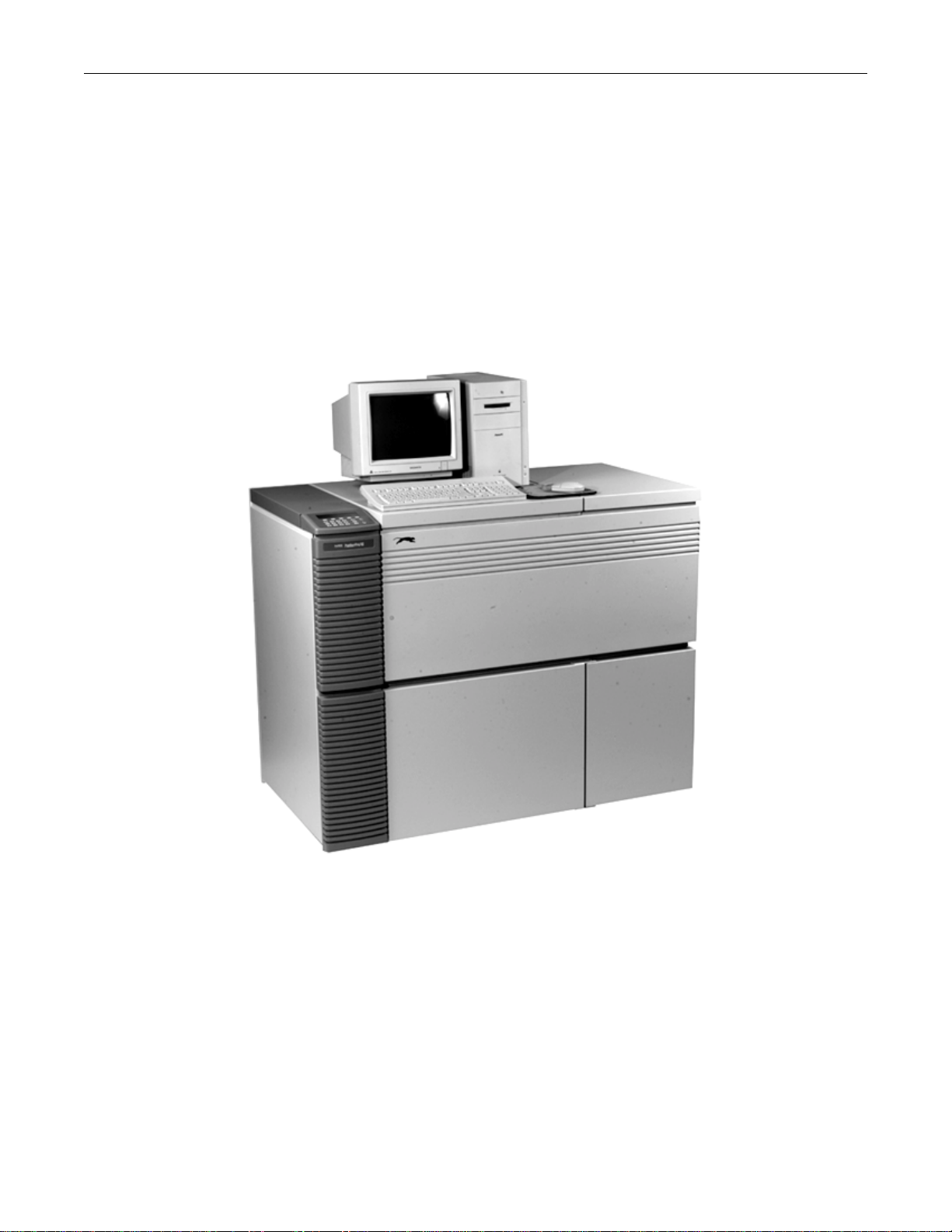
2-1 PantherPro/46 System Overview (Refer to Figure 2-1)
Supporting multiple input ports and media widths up to 18.1" (460mm), the PantherPro/46 is a
fast, commercial quality, high resolution, imagesetting system designed for high-production
applications where wide-measure imaging is required.
PantherPro/46 Imagesetting System
Figure 2-1
The Multiport™ multiplexing architecture feature allows up to four RIPs to drive a single film
recorder, and allows the addition of multiple recorders. The PantherPro/46 Image Recorder
provides a cost effective solution for environments requiring high quality, high speed,
monochromatic or color integrated text and graphics production in a wide-measure format.
The PantherPro/46 imagesetting systems feature both modular RIP and image recorder
subsystems. The RIP subsystem consists of Adobe's CPSI PostScript Level 2 RIP running on
a standard microcomputer platform. Also available as an option is the PixelBurst™ co-

TP8251 PantherPro/46 Image Recorder
2-2 PrePRESS SOLUTIONS CONFIDENTIAL October 1995
processor (Macitosh™ Platform), which provides significant speed improvements in RIPing
image-intensive jobs.
The PantherPro/46 image recorder subsystem is contained in a freestanding cabinet that is
supported by four casters, two of which can swivel. Adjustable gliders are located adjacent to
the casters for securing and leveling the recorder position.
The Multiport™ feature allows the recorder to be driven by up to four RIPs, each connected to
the PantherPro/46 using a SCSI (Small Computer Systems Interface) bus. The recorder can
be configured with up to four SCSI buses, each with a SCSI IN and SCSI OUT port. The
input/output ports allow you to create a daisy chain link of up to seven SCSI devices on one
SCSI bus. For example, the optional Panther Color or Plain Paper Laser printer can be
connected to the SCSI OUT port.
A standard PantherPro/46 image recorder offers ten resolution settings from 900 DPI (39.9"
per minute) to 3048 DPI (9.8" per minute) with one input port and dual 500+ MB hard disk
drives. Media widths from 12" (30.5 cm) to 18.1" (46 cm) can be loaded into the
PantherPro/46 image recorder. (The PantherPro/36 accepts media widths up to 14.1".) A
smart cassette and power-operated media cutter are also included as a standard feature.
Optionally, single input port systems can be configured with dual 1+ GB Page Buffer hard
disk drives. Up to three additional input ports can be added, each configured with either a
500+ MB or 1+ GB Page Buffer hard disk drives to accept input data from up to four Panther
RIPs. A pin registration punch system and an on-line processor interface are also available
as an option. Refer to the PantherPro/46 User's Guide for additional system configurations
and performance-enhancing options, such as:
• ESCOR II™ and ESCOR-FM™ screening
• VIM™: PrePRESS' OPI-compliant image management system
• PixelBurst™ accelerator card for faster RIPing times (Macintosh Platforms only)
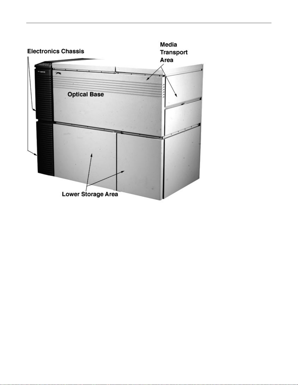
2-2 PantherPro/46 Image Recorder Hardware Overview
The components of the PantherPro/46 recorder are located in three separate areas of the
cabinet: electronics chassis, optical base, and media transport. The lower storage area is part
of the cabinet internal main frame that supports the major components and covers.
Refer to Figure 2-2 on the next page.
PanthePro/46 Image Recorder TP8251
October 1995 PrePRESS SOLUITIONS CONFIDENTIAL 2-3
PantherPro/46 Component Areas
Figure 2-2
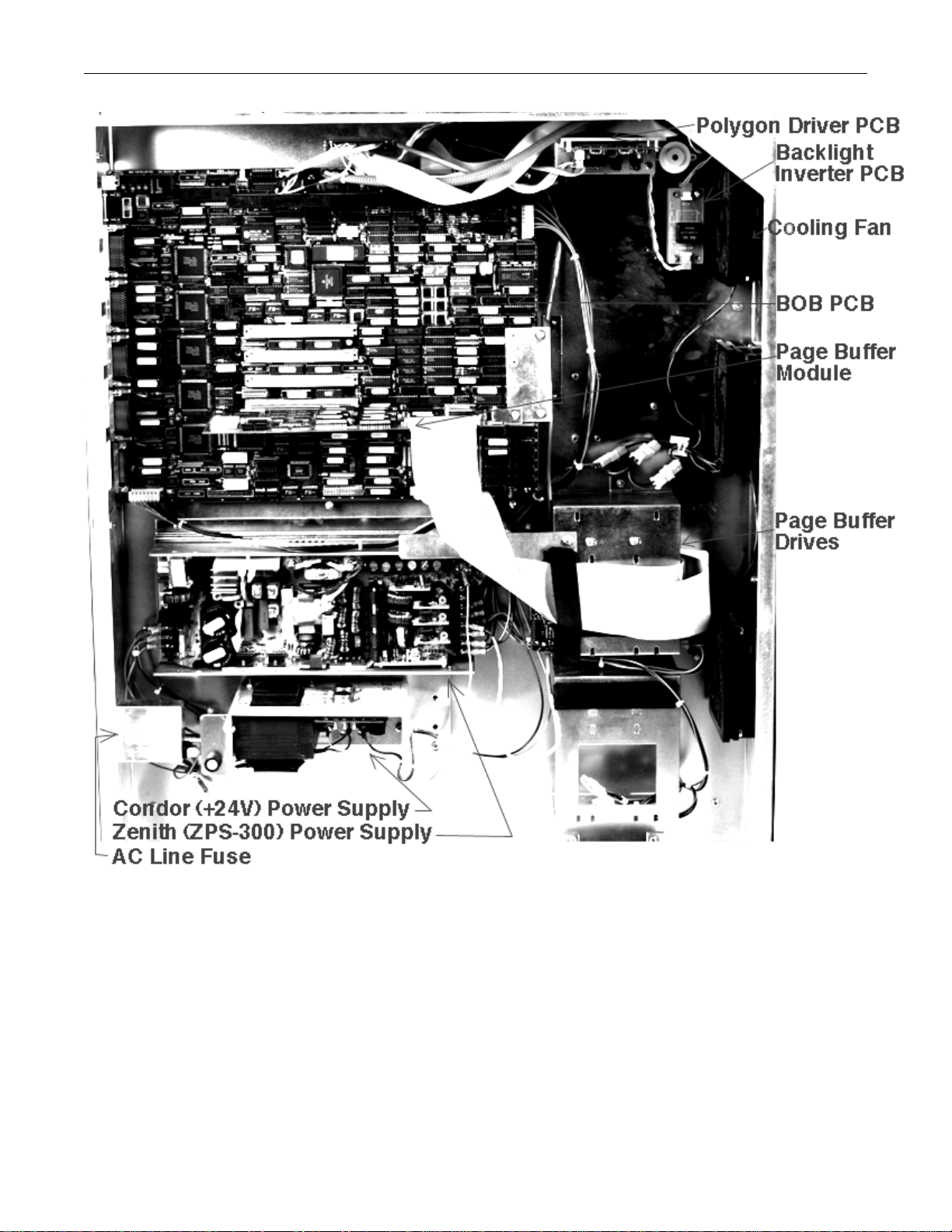
2-2.1 Electronics Chassis (Refer to Figure 2-3)
The electronics chassis is mounted on the left side of the cabinet. The major components
contained in the electronics area include:
• Controller Board (WCB/BOB) and plug-in Page Buffer Module(s)
• Polygon Driver PCB
• Page Buffer Drives
• Graphics LCD and Terminator PCB
• Zenith ZPS-300 Switching Power Supply (+5v, -12v, +12, +12v)
• Condor Polygon Power Supply (+24v)
• Back Light Inverter PCB
• AC Line Fuse (2)
• Cooling Fans (3)
Refer to Section 3 for a description of each component.
TP8251 PantherPro/46 Image Recorder
2-4 PrePRESS SOLUTIONS CONFIDENTIAL October 1995
PantherPro/46 Electronics Chassis Component Layout
Figure 2-3

PanthePro/46 Image Recorder TP8251
October 1995 PrePRESS SOLUITIONS CONFIDENTIAL 2-5
2-2.2 Recorder Optical Bed
The optical components are mounted on a rigid base casting and are under the optics cover
and supply cassette bottom shield. The major components contained in the recorder optics
bed include:
• Polygon
• Scan Lens
• High Speed Laser Amplifier Board
• Laser Driver/Laser Tube Assembly
• 1st Cylinder Lens
• Beam steering Mirror
• Second Cylinder Lens and Mask
• Start Of Line Sensor/Start Of Line Amplifier Assembly (SOL)
Refer to figure 2-4 for the recorder optical components.

TP8251 PantherPro/46 Image Recorder
2-6 PrePRESS SOLUTIONS CONFIDENTIAL October 1995
PantherPro/46 Optical Components
Figure 2-4

PanthePro/46 Image Recorder TP8251
October 1995 PrePRESS SOLUITIONS CONFIDENTIAL 2-7
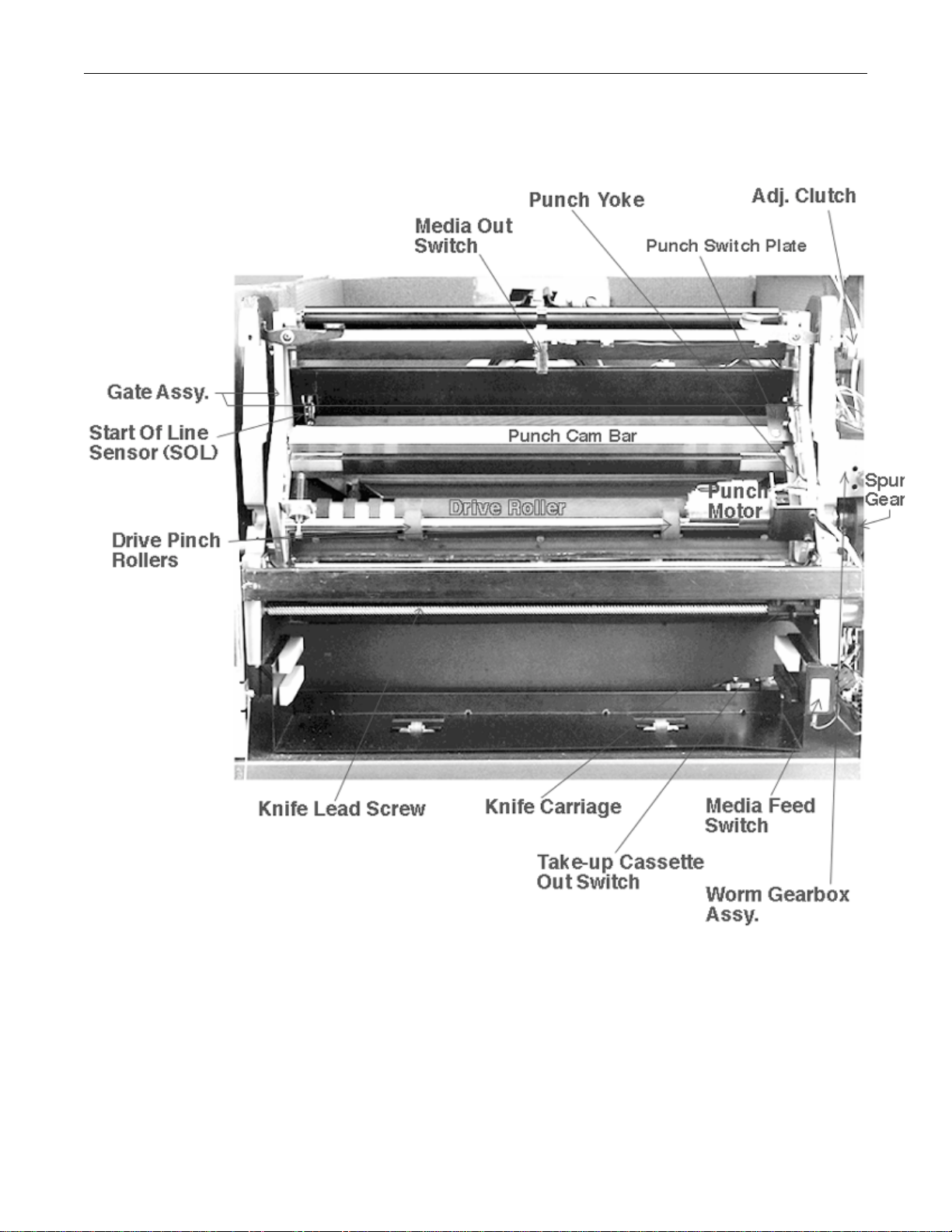
2-2.3 Recorder Media Transport and Drive (Refer to Figure 2-5)
PantherPro/46 mechanical components such as rollers, motors, and inter-lock switches are
located in the media transport section. The media transport components are easily accessed
by lifting the supply cassette cover (and in some cases, the rear access panel). The media
drive components are accessed by removing the rear access panel. The major components
contained in the recorder media transport and drive include:
• Smart Supply Cassette
• Drag Roller and Clutch
• Gate Assembly
• Media Out Switch
• Drag-Pinch Roller
• Optional Pin Registration Punch System
• Image Roller
• Drive-Pinch Rollers
• Laser Safety Interlocks
• Worm Gearbox Assy.
• Leading Motor/Encoder
• Drive Roller
• Spur Gear
• Power Knife
• Knife Carriage Assy.
• Motor Assembly
• Lead Screw
• Stationary Knife
• Pressure Plate
• Media Guides (upper, lower)
• Knife Electronic-Opto Sensors (2)
• Manual Feed Push Button
• Cassette Out Switch
• Take-Up Cassette
• Take-Up Catch Rollers
• Take-Up Access Door Open Switch
TP8251 PantherPro/46 Image Recorder
2-8 PrePRESS SOLUTIONS CONFIDENTIAL October 1995
PantherPro/46 Media Transport
Figure 2-5

PanthePro/46 Image Recorder TP8251
October 1995 PrePRESS SOLUITIONS CONFIDENTIAL 2-9
2-3 Electrical Power Requirements (Refer to Figure 2-6)
Power line to be minimum 10 amp rating, with isolated 3rd wire ground. AC receptacle
should be Hubbel outlet Part Number IG5262 or equivalent.
Input Voltage/Power Line 115 VAC+/-10%, 2 amps, single phase, 50-60Hz
230 VAC+/-10%, 1 amp, single phase, 50-60Hz
Power Consumption Approximately 175 watts, AC
Heat Dissipation Approximately 600 BTU/hr.
Input Voltage Power Line
Figure 2-6

TP8251 PantherPro/46 Image Recorder
2-10 PrePRESS SOLUTIONS CONFIDENTIAL October 1995
2-4 PantherPro/46 Recorder Specifications
Maximum Line Length: 18.1 inch (460 mm)
Resolutions (H x V): 3048 x 3048, 1524 x 1524 (can be imaged 1524 x 3048)
2540 x 2540, 1270 x 1270 (can be imaged 1270 x 2540)
2400 x 2400, 1200 x 1200 (can be imaged 1200 x 2400)
2032 x 2032, 1016 x 1016 (can be imaged 1016 x 2032)
1800 x 1800, 900 x 900 (can be imaged 900 x 1800)
Spot Size: 15µ(.0006") @ 1800 dpi to 3048 dpi
30µ(.0012") @ 900 dpi to 1524 dpi
Absolute Accuracy: ±0.004 inch over 18 inch
Repeatability: ±0.001 inch typical over 8 contiguous color separations
nominal 18" in length *
Linearity: ±0.001%, measured from center of image
Imaging Speed: 3048 x 3048 dpi: 11.6 inches/minute (249mm/min)
2540 x 2540 dpi: 13.9 inches/minute (353mm/min)
2400 x 2400 dpi: 14.7 inches/minute (373mm/min)
2032 x 2032 dpi: 17.4 inches/minute (442mm/min)
1800 x 1800 dpi: 19.7 inches/minute (500mm/min)
1524 x 1524 dpi: 23.2 inches/minute (589mm/min)
1270 x 1270 dpi: 27.9 inches/minute (709mm/min)
1200 x 1200 dpi: 29.5 inches/minute (749mm/min)
1016 x 1016 dpi: 34.8 inches/minute (884mm/min)
900 x 900 dpi: 39.3 inches/minute (998mm/min)
(Imaging speed does not include processing and RIPing
time)
Recording Method: Visible Red Laser Diode (wavelength: 670nm)
Page Buffer Disk Drive(s): The standard single input port system is equipped with dual
500+ MB Page Buffer hard disk drives.
Options:
Dual 1+ GB Page Buffer hard disk drives for increased file
stacking capability.
Up to three additional ports with 500+ or 1 + GB page buffer
hard disk drives.
Page buffer drives for input ports must match in capacity.
Multiport: Up to 3 additional input ports can be added, each
supporting either a 500+MB or 1+GB Page Buffer hard
disk drive, for a total of 4 input ports with 5 Page Buffer
hard drives to accept input from up to 4 RIPs.
Table of contents
Other PrePRESS Office Equipment manuals


