PrePRESS PANTHER PRO User manual

PantherPro Image Recorder TP 8250
iJune 1994 PrePRESS SOLUTIONS
Table of Contents
Section 1 General Service Information Page
1-1 Scope of Manual . . . . . . . . . . . . . . . . . . . . . . . . . . . . . . . . . . . . . . . . . . 1-1
1-2 Laser Information . . . . . . . . . . . . . . . . . . . . . . . . . . . . . . . . . . . . . . . . . . 1-2
1-3 Regulatory Agencies Information. . . . . . . . . . . . . . . . . . . . . . . . . . . . . . 1-4
1-4 Electrostatic Discharge - ESD . . . . . . . . . . . . . . . . . . . . . . . . . . . . . . . . 1-4
Section 2 Overview and Specifications
2-1 Product Overview. . . . . . . . . . . . . . . . . . . . . . . . . . . . . . . . . . . . . . . . . . 2-1
2-2 Hardware Overview . . . . . . . . . . . . . . . . . . . . . . . . . . . . . . . . . . . . . . . . 2-2
2-3 Electrical Power Requirements . . . . . . . . . . . . . . . . . . . . . . . . . . . . . . . 2-5
2-4 Product Specifications . . . . . . . . . . . . . . . . . . . . . . . . . . . . . . . . . . . . . . 2-6
Section 3 Theory of Operation
3-1 Panther Pro Overview . . . . . . . . . . . . . . . . . . . . . . . . . . . . . . . . . . . . . . 3-1
3-2 High Speed Control (HSCB) . . . . . . . . . . . . . . . . . . . . . . . . . . . . . . . . . 3-2
3-3 CPU and Peripherals Module Overview . . . . . . . . . . . . . . . . . . . . . . . . 3-2
3-4 Page Buffer Module Overview . . . . . . . . . . . . . . . . . . . . . . . . . . . . . . . . 3-4
3-5 Recorder Output Module Overview . . . . . . . . . . . . . . . . . . . . . . . . . . . . 3-5
3-6 Media Transport. . . . . . . . . . . . . . . . . . . . . . . . . . . . . . . . . . . . . . . . . . . 3-7
3-7 Optics. . . . . . . . . . . . . . . . . . . . . . . . . . . . . . . . . . . . . . . . . . . . . . . . . . . 3-9
Section 4 Power Supply and Distribution
4-1 AC Power. . . . . . . . . . . . . . . . . . . . . . . . . . . . . . . . . . . . . . . . . . . . . . . . 4-1
4-2 DC Power. . . . . . . . . . . . . . . . . . . . . . . . . . . . . . . . . . . . . . . . . . . . . . . . 4-3
Section 5 Installation
5-1 Bill of Materials. . . . . . . . . . . . . . . . . . . . . . . . . . . . . . . . . . . . . . . . . . . . 5-1
5-2 Pre-Installation Procedures . . . . . . . . . . . . . . . . . . . . . . . . . . . . . . . . . . 5-1
5-3 Electrical Requirements . . . . . . . . . . . . . . . . . . . . . . . . . . . . . . . . . . . . . 5-2
5-4 Installation Procedures . . . . . . . . . . . . . . . . . . . . . . . . . . . . . . . . . . . . . 5-2
5-5 System Test . . . . . . . . . . . . . . . . . . . . . . . . . . . . . . . . . . . . . . . . . . . . . . 5-3
5-6 Installation Completion. . . . . . . . . . . . . . . . . . . . . . . . . . . . . . . . . . . . . . 5-3

PantherPro Image Recorder
ii June 1994
TP 8250
PrePRESS SOLUTIONS
Section 6 Removal/Replacement Page
6-1 External Covers and Panels . . . . . . . . . . . . . . . . . . . . . . . . . . . . . . . . . 6-1
6-2 E. M. I. Shield. . . . . . . . . . . . . . . . . . . . . . . . . . . . . . . . . . . . . . . . . . . . . 6-4
6-3 Keypad/LCD Assembly . . . . . . . . . . . . . . . . . . . . . . . . . . . . . . . . . . . . . 6-5
6-4 Electronics Assembly. . . . . . . . . . . . . . . . . . . . . . . . . . . . . . . . . . . . . . . 6-5
6-5 Fan Assembly . . . . . . . . . . . . . . . . . . . . . . . . . . . . . . . . . . . . . . . . . . . . 6-5
6-6 Power Supply. . . . . . . . . . . . . . . . . . . . . . . . . . . . . . . . . . . . . . . . . . . . . 6-5
6-7 I/O Panel Assembly . . . . . . . . . . . . . . . . . . . . . . . . . . . . . . . . . . . . . . . . 6-6
6-8 Polygon Motor Assembly . . . . . . . . . . . . . . . . . . . . . . . . . . . . . . . . . . . . 6-6
6-9 Laser Amplifier PCB. . . . . . . . . . . . . . . . . . . . . . . . . . . . . . . . . . . . . . . . 6-6
6-10 Polygon Driver PCB . . . . . . . . . . . . . . . . . . . . . . . . . . . . . . . . . . . . . . . . 6-6
6-11 Laser Diode Assembly . . . . . . . . . . . . . . . . . . . . . . . . . . . . . . . . . . . . . . 6-7
6-12 Second Cylinder Lens Assembly . . . . . . . . . . . . . . . . . . . . . . . . . . . . . . 6-8
6-13 Start Of Line Sensor PCB . . . . . . . . . . . . . . . . . . . . . . . . . . . . . . . . . . . 6-8
6-14 Paper Feed Gate Assembly. . . . . . . . . . . . . . . . . . . . . . . . . . . . . . . . . . 6-9
6-15 Gate Assembly Rollers . . . . . . . . . . . . . . . . . . . . . . . . . . . . . . . . . . . . 6-10
6-16 Metering Roller. . . . . . . . . . . . . . . . . . . . . . . . . . . . . . . . . . . . . . . . . . . 6-11
6-17 Drive Roller . . . . . . . . . . . . . . . . . . . . . . . . . . . . . . . . . . . . . . . . . . . . . 6-12
6-18 Knife Carriage Assembly . . . . . . . . . . . . . . . . . . . . . . . . . . . . . . . . . . . 6-13
6-19 Servo Leading Motor and Gearbox Assembly . . . . . . . . . . . . . . . . . . . 6-14
6-20 Servo Leading Motor . . . . . . . . . . . . . . . . . . . . . . . . . . . . . . . . . . . . . . 6-15
6-21 Leading Worm . . . . . . . . . . . . . . . . . . . . . . . . . . . . . . . . . . . . . . . . . . . 6-15
6-22 Leading Spur Gear. . . . . . . . . . . . . . . . . . . . . . . . . . . . . . . . . . . . . . . . 6-16
Section 7 Diagnostics
7-1 Overview . . . . . . . . . . . . . . . . . . . . . . . . . . . . . . . . . . . . . . . . . . . . . . . . 7-1
7-2 PROM Resident Diagnostics . . . . . . . . . . . . . . . . . . . . . . . . . . . . . . . . . 7-1
Section 8 Reference/Adjustments
8-1 Jumpers, LED’s, and Switches . . . . . . . . . . . . . . . . . . . . . . . . . . . . . . . 8-1
8-2 Laser Amp 7.5V reference Adjustment . . . . . . . . . . . . . . . . . . . . . . . . . 8-4
8-3 Laser Amp Offset Adjustment . . . . . . . . . . . . . . . . . . . . . . . . . . . . . . . . 8-5
7-2.1 Level 1 Power-up Test . . . . . . . . . . . . . . . . . . . . . . . . . . . . . . . . . . . . . . 7-1
7-2.2 PROM Monitor . . . . . . . . . . . . . . . . . . . . . . . . . . . . . . . . . . . . . . . . . . . . 7-2
7-2.3 Level 2 Diagnostics . . . . . . . . . . . . . . . . . . . . . . . . . . . . . . . . . . . . . . . . 7-2
7-3 Disk Based Diagnostics . . . . . . . . . . . . . . . . . . . . . . . . . . . . . . . . . . . . . 7-4
7-3.1 HSCB_Diag . . . . . . . . . . . . . . . . . . . . . . . . . . . . . . . . . . . . . . . . . . . . . . 7-4
7-4 Keypad Diagnostics . . . . . . . . . . . . . . . . . . . . . . . . . . . . . . . . . . . . . . . . 7-7
7-4.1 Level 2 Tests . . . . . . . . . . . . . . . . . . . . . . . . . . . . . . . . . . . . . . . . . . . . . 7-7
7-4.2 Disk Based Utilities . . . . . . . . . . . . . . . . . . . . . . . . . . . . . . . . . . . . . . . . 7-8
7-4.3 Communications Utilities . . . . . . . . . . . . . . . . . . . . . . . . . . . . . . . . . . . . 7-9
7-4.4 SCSI Downloader Utilities . . . . . . . . . . . . . . . . . . . . . . . . . . . . . . . . . . 7-10

PantherPro Image Recorder TP 8250
iiiJune 1994 PrePRESS SOLUTIONS
Section 9 PantherPro Parts Listing
Group 1 Case and Covers Front View . . . . . . . . . . . . . . . . . . . . . . . . . . . . . . . 9-2,3
Group 1A Case and Covers Rear View - I/O Panel . . . . . . . . . . . . . . . . . . . . . . 9-4,5
Group 2 Front Components . . . . . . . . . . . . . . . . . . . . . . . . . . . . . . . . . . . . . . . 9-6,7
Group 3 Optics, Laser Diode/Amp, Polygon . . . . . . . . . . . . . . . . . . . . . . . . . . 9-8,9
Group 4, 4A Paper Feed Transport . . . . . . . . . . . . . . . . . . . . . . . . . . . . . . . . . . 9-10,14
Group 4B Paper Feed Drive. . . . . . . . . . . . . . . . . . . . . . . . . . . . . . . . . . . . . . 9-14, 15
Group 5 Power Supply Drawer . . . . . . . . . . . . . . . . . . . . . . . . . . . . . . . . . . 9-16, 17
Group 6 Card Cage (PCB'S) . . . . . . . . . . . . . . . . . . . . . . . . . . . . . . . . . . . . 9-18, 19
Group 7 Take-Up Cassettes . . . . . . . . . . . . . . . . . . . . . . . . . . . . . . . . . . . . 9-20, 21
Group 8 Supply Cassettes, ETM Assembly. . . . . . . . . . . . . . . . . . . . . . . . . 9-22, 23

PantherPro Image Recorder
iv June 1994
TP 8250
PrePRESS SOLUTIONS

PantherPro Image Recorder TP 8250
vJune 1994 PrePRESS SOLUTIONS
PantherPro
IMAGESETTER
TECHNICAL MANUAL
TP 8250
November 1994
PrePRESS SOLUTIONS CONFIDENTIAL
2

PantherPro Image Recorder TP 8250
1-1November 1994 PrePRESS SOLUTIONS CONFIDENTIAL
Section 1 General Service Information
1-1 Scope of Manual
The Model PantherPro Image Recorder Service Manual is intended for the use of trained
technical representatives of PrePRESS SOLUTIONS, its subsidiaries and dealers. It is not
intended as a substitute for training. Service personnel will utilize this document as a re-
source for information concerning the following aspects of effective service:
Section 1. “General Service Information”, contains general information regarding the
service manual, laser safety information, regulatory agencies information, and
electro static discharge prevention rules.
Section 2. “Overview and Specifications”, describes the features of the PantherPro and
products specifications.
Section 3. “Theory of Operation”, describes in detail the functionality of the PantherPro.
Section 4. “Power Supply and Distribution”, contains details regarding the DC and AC
power used on the PantherPro.
Section 5. “Installation”, contains the installation instructions for the PantherPro.
Section 6. “Removal/Replacement”, contains removal/replacement procedures for items
that are normally removed for servicing.
Section 7. “Diagnostics”, contains diagnostics procedures normally performed on the
PantherPro.
Section 8. “Reference/Adjustments”, contains reference material and adjustments proce-
dures normally performed on the PantherPro.
Section 9. “Parts Catalog”, contains the catalog which identifies and list part numbers of
the PantherPro.

PantherPro Image Recorder
1-2 November 1994
TP 8250
PrePRESS SOLUTIONS CONFIDENTIAL
1-2 Laser Safety Information
CAUTION - Use of controls or adjustments or performance of procedures other than
those specified herein may result in hazardous radiation exposure.
Classification and Labeling of Laser Product
According to the Code of Federal Regulations, laser products are classified in Classes I
through IV. These classes are assigned according to the amount of laser radiation acces-
sible to the operator. The PantherPro Image Recorder is certified as a Class I product. The
operator is not exposed to any hazardous laser radiation during operation and mainte-
nance.
The laser itself, however, is a Class IIIb laser, and emits laser radiation which is considered
hazardous according to the Federal Code of Regulations, section 1040.10. This level of
radiation is not accessible to the operator as long as the optics cover of the PantherPro is
not removed.
The PantherPro uses a low-power, 5 milliwatts laser diode which only emits visible red
light. As with any bright source of optical energy, safety precautions should be applied. One
should not stare into the beam or any reflections from shiny sources.
Laser Warning Labels
Figure 1-1 represents the laser warning label. This label is located inside the PantherPro on
a protective panel that encloses the laser optics, on the rear panel, and the electronics
cover. (See Figure 1-2).
CAUTION - LASER RADIATION WHEN OPEN.
AVOID DIRECT EXPOSURE TO BEAM.
ATTENTION - RAYONNEMENT LASER EN CAS
D’OUVERTURE. EXPOSITION DANGEREUSEAU FAISCEAU
Safety Label
Figure 1-1
Operator Safety
Operator access to laser radiation is not possible during operation or operator mainte-
nance. During operation the protective housing prevents access to all radiation fields. The
recorder hinged supply cassette cover may safely be opened for operator maintenance.
This maintenance includes removing and installing the photographic media supply and
take-up cassettes.
To insure safety during maintenance, redundant interlocks shut off power to the laser diode

PantherPro Image Recorder TP 8250
1-3November 1994 PrePRESS SOLUTIONS CONFIDENTIAL
Laser Warning Labels
Laser Warning Label Locations
Figure 1-2
assembly (laser diode power up to 5 milliwatts at 670 nanometers could be accessible in
the machine interior if the interlocks are defeated). The PantherPro electronics and optics
covers should never be removed by the customer.
Servicing Safety
Service procedures include removal of the machine covers to replace or adjust compo-
nents. The inner laser assembly and other components may be replaced in the field. The
laser output and the focused beam are accessible in the interior.
The supply cassette door includes two magnetic interlock switches which are mounted and
connected in series so that if the access door is lifted, both switches open to open the
interlock circuit. When the interlock circuit is open, all power is dropped to the current
source for the laser diode.
All service procedures will be performed with the main power shut off and with the safety
interlock circuit open (no laser diode current).
When performing alignments, carefully follow the procedures documented in the technical
manual. DO NOT defeat the safety interlock switches unless specified in the procedure.
Also, NEVER override the safety interlock switches if the polygon/motor assembly is not
spinning, as this could allow the focused beam to be emitted.

PantherPro Image Recorder
1-4 November 1994
TP 8250
PrePRESS SOLUTIONS CONFIDENTIAL
Caution: Direct or indirect reflected eye contact with the laser beam may cause
serious eye damage.
Warning: At no time should the unit be left unattended with the interlocks defeated.
The following safety precautions should always be observed:
1. Never operate the unit with the optics cover removed.
2. Laser safety goggles must be worn when making any adjustments to the recorder with
the interlocks defeated.
3. Any adjustments that are to be made with the interlocks defeated must be made in a
secure area, with only trained personnel present.
4. Do not place screwdrivers or other shiny objects in the path of the laser beam.
5. Remove all jewelry from fingers and wrists before making any alignments.
6. Remember that the laser beam is invisible and can cause permanent damage to the
eyes.
1-3 Regulatory Agencies Information
The PantherPro is an approved product designed and manufactured in accordance with UL
(Underwriters Laboratories) and CSA (Canadian Standards Association) standards. The
product also complies with the requirements in Part 15 of FCC Rules for a Class A comput-
ing device.
This equipment complies with the requirements in part 15 of FCC Rules for a Class A
computing device. Operation of this equipment in a residential area may cause unaccept-
able interference to radio and TV reception requiring the operator to take whatever steps
are necessary to correct the interference.
The PantherPro also complies with specific European safety standards; international mod-
els are shipped with a label bearing the “CE” mark. This label demonstrates compliance
with IEC safety standards. The PantherPro also meets EN55022/VDE Class B emissions
standards.
1-4 Electrostatic Discharge - ESD
Static electricity is, simply, electricity that is not moving. It is harmless as long as it remains
static. Unfortunately, an electrical charge is unstable and is always looking for an opposite
charge to unite with. When a charge moves, it becomes a current, which is often greater
than a electronic circuit can handle.
The smallest static charge that can be felt is 3,000 volts; the smallest charge that can be

PantherPro Image Recorder TP 8250
1-5November 1994 PrePRESS SOLUTIONS CONFIDENTIAL
seen is 5,000 volts; and the smallest charge that can be heard is 10,000 volts. Some semi-
conductor devices are susceptible to a static charge as little as 10 volts.
Electrostatic discharge has become more and more of a hazard as microcircuit compo-
nents have become smaller and more sensitive.
ESD Prevention Rules
These are the rules to be learned and followed in order to prevent ESD damage to elec-
tronic printed circuit boards and assemblies.
WARNING: Make sure you are NOT grounded when working on equipment that is
plugged in and ON.
1. Always use the antistatic portable field service kit when working on electronic parts of
PrePRESS Solution’s products or when handling printed circuit boards.
2. Make sure machine is plugged in a grounded outlet (and switched off) if using the ma-
chine frame as a grounding point.
3. Make sure your wrist strap and antistatic service kit are connected together and con-
nected to ground.
4. When replacing printed circuit boards, remove the old board from the machine before
removing replacement board from the antistatic bag. Then install replacement board
and place old board in the antistatic bag.
5. Always transport and store electronic components in an antistatic bag.
6. Use the correct size bag, not too big or not too small.
7. Keep antistatic bags in good condition. Bags with pin holes, rips, tears, or crumpled
bags are less efficient and may provide little or no protection.
8. Do not remove components from bags just to look at them. You can usually see through
the bag to identify the part.
9. Keep spare bags on hand.
10.Always ship back field returns in an antistatic bag. Even defective components should
be stored and transported in antistatic bags so that they are not damaged further.
11.Keep static producing materials such as polyester, plastic, and Styrofoam away from elec-
tronic parts.
12.Don’t pick up boards unless you are grounded or the boards are in antistatic bags. Do
not touch edge connectors on PCB’s, or exposed circuitry. Handle IC’s, and boards by

PantherPro Image Recorder
1-6 November 1994
TP 8250
PrePRESS SOLUTIONS CONFIDENTIAL
the edges, and never place components on metal surfaces.
13.Static is present at all times, more so when the humidity is low.
14.Educate customers about static protection, especially the ones who maintain their own
equipment.
PantherPro Image Recorder TP 8250
2-1November 1994 PrePRESS SOLUTIONS CONFIDENTIAL
Section 2 Overview and Specifications
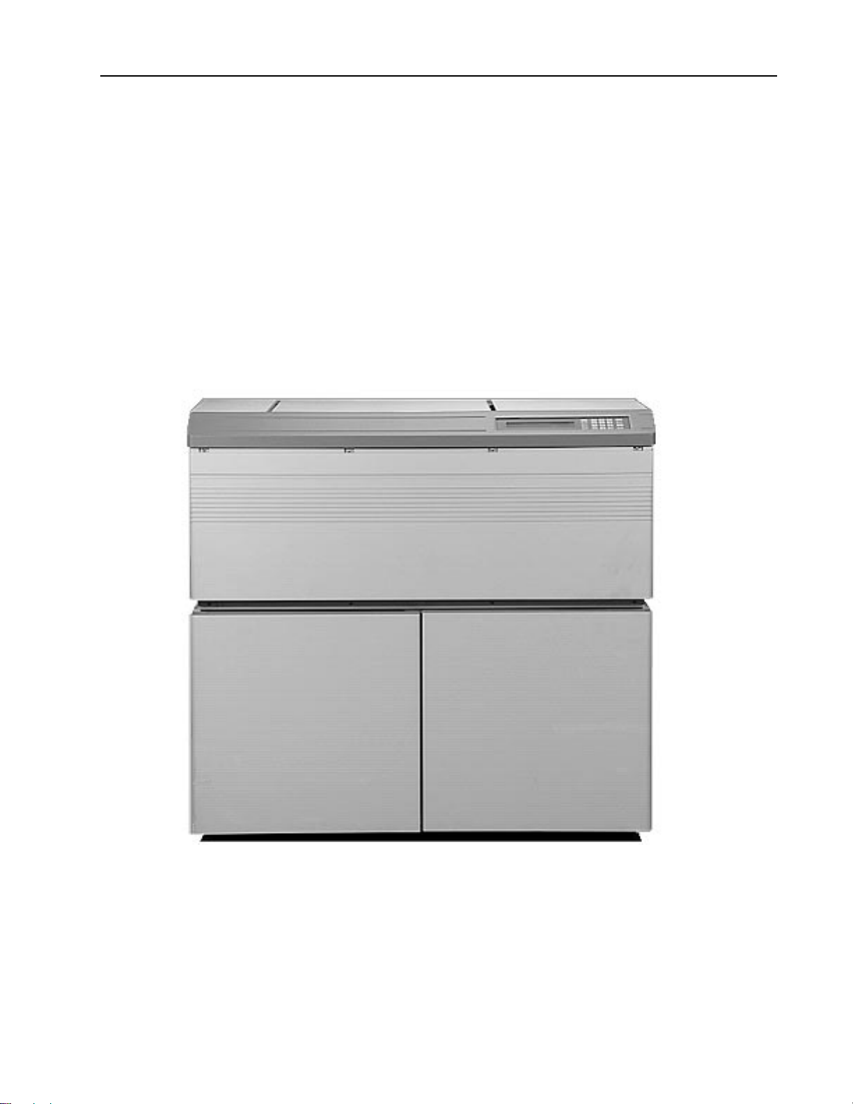
2-1 Product Overview
The PrePRESS PantherPro is a high speed, high-resolution, multiport image recorder. At a
recording speed of 53.3"/min, the Model PantherPro is the fastest image recorder on the
market.
PantherPro with Base Cabinet
Figure 2-1
The Model PantherPro includes the Multiport option, which allows up to four RIPs to drive a
single PantherPro. The PantherPro is designed for configuration
PantherPro Image Recorder
2-2 November 1994
TP 8250
PrePRESS SOLUTIONS CONFIDENTIAL
with the Adobe CPSI Level 2 software RIP.The PantherPro is driven by a standand plat-
form microcomputer via a SCSI interface.The PantherPro offers VIM Intergrator as stan-
dard which provides OPI and DCS back-end intergration compatability.
A standard PantherPro offers ten standard resolution settings from 900 to 3048 dpi, one
input port and dual 500+ hard disk drives. Among the Pro's options are dual 1+GB Page
Buffer hard disk drives and up to three addional input ports can be added. A Pro may be
configured with either a single 500+MB or single 1+GB Page Buffer hard disk drive. All
Page Buffer Drives must be the same size.
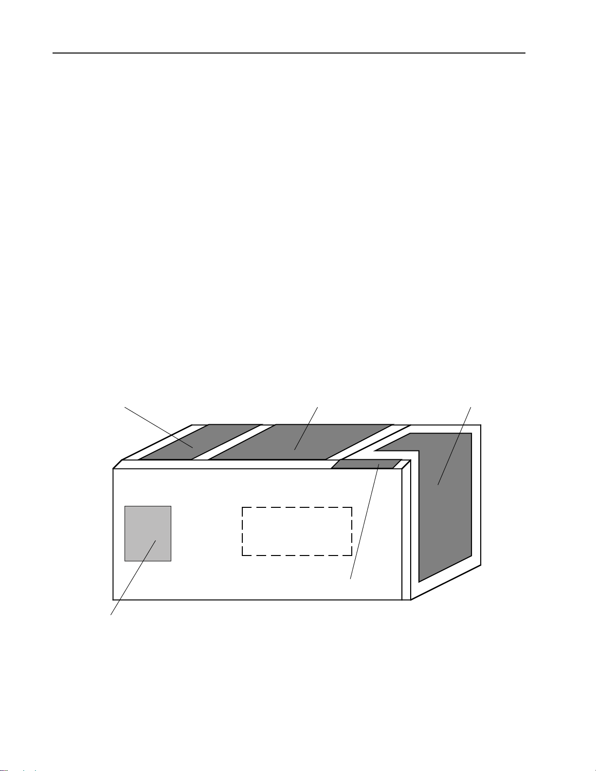
2-2 Hardware Overview
The components of the PantherPro are located in four separate areas of the cabinet: card
cage/power supply, operator control panel, laser/optics and media transport. (Refer to Figure
2-2)
Power Supply
Drawer
Operator Panel
Page Buffers Figure 2-2 PantherPro Component Areas
Laser/OpticsHSCB / PB Module Media Transport
PantherPro Image Recorder TP 8250
2-3November 1994 PrePRESS SOLUTIONS CONFIDENTIAL
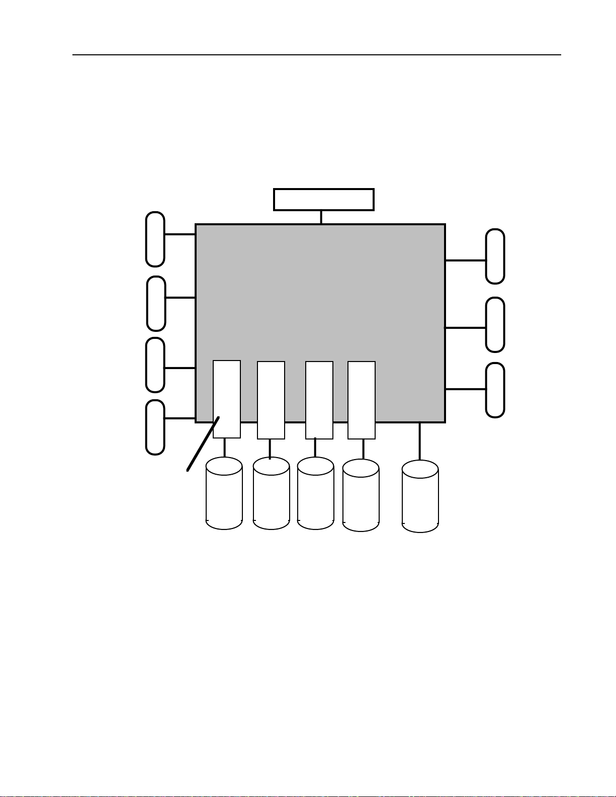
2-2.1 HSCB / PB Module (Refer to Figure 2-3, Electronics Block Diagram)
The HSCB / PB Module area is located on the left side of the cabinet and contains the High
Speed Controller Board and Page buffer Modules.
Refer to Section 3 for description of the High Speed Controller Board and Page buffer
Modules.
PantherPro Electronics Block Diagram
Figure 2-3
2-2.2 Operator Control Panel
The operator control panel is located in top front of the cabinet and is used for operator
HSCB
PB 4
Motors
Video
Debug
LCD / Keypad
S
C
S
N
P
U
T
S
Page Buffer Module PB 3 PB 2 PB 1 PB 0
I
I
interaction with the system and for displaying operational and error messages.

PantherPro Image Recorder
2-4 November 1994
TP 8250
PrePRESS SOLUTIONS CONFIDENTIAL
2-2.3 Laser, Optics and Media Transport
(Refer to Figure 2-4, Recorder Components Block Diagram)
The major components contained in the recorder area include:
Laser Amplifier PCB
Laser Driver PCB/Laser Diode Assembly
Leading Motor/Encoder
Polygon Motor
Polygon Drive PCB
Paper Transport Assembly
Optical System
Sensors and Switches
HSCB
Polygon High Speed Transport Motors
Driver Laser Amp Leading/Cutter
Polygon High Speed
Motor Laser Driver
Panther Pro Recorder Components Block Diagram
Figure 2-4
The recorder components, upon input from the HSCB, generates typographic characters
and graphics onto visable red sensitive paper, film or plate material.
The images are formed on the media by a laser beam output which is generated by the
video data received from the image controller. The video data is received by the laser
amplifier PCB, which then output the data to the laser driver PCB and onto the laser diode.
The laser diode generates the visable red laser beam which is dispersed across the imag-
ing area by a polygon scanner motor and optical system. The paper is moved across the
imaging area by a servo leading motor.
PantherPro Image Recorder TP 8250
2-5November 1994 PrePRESS SOLUTIONS CONFIDENTIAL
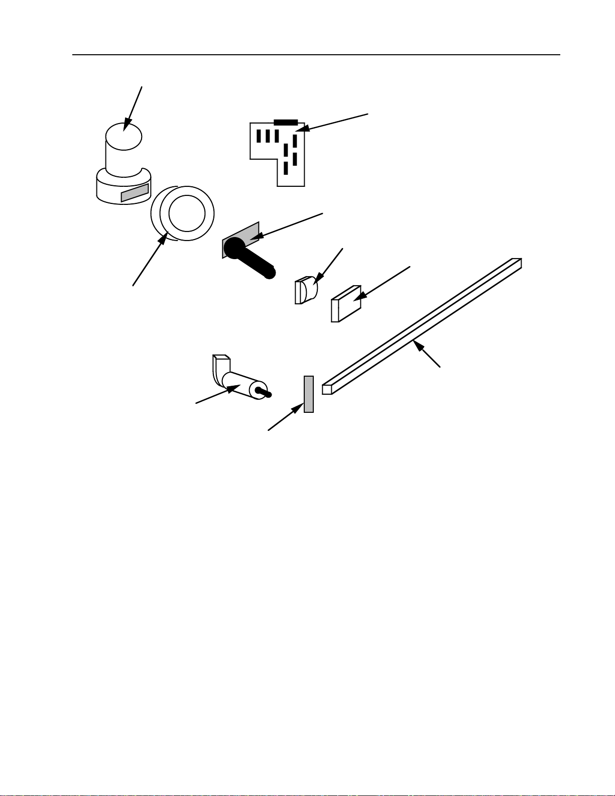
PantherPro Recorder Components
Figure 2-5
2-3 Electrical Power Requirements
Power line to be minimum 15 amp rating, isolated with 3rd wire insulated ground wire. AC
receptacle should be Hubbel outlet Part Number IG5262 or equivalent. Refer to Figure 2-6.
Input Voltage/Power Line 115 VAC+/-10%, 60 Hz+/-3 Hz
230 VAC+/-10%, 50 Hz+/-3 Hz
Input Current Rating 2 amps/115 VAC
1 amps/230 VAC
Power Consumption 150 watts
POLYGON SCANNER MOTOR
LASER AMPLIFIER PCB
LASER DRIVER/LASER DIODE ASSEMBLY
FIRST CYLINDRICAL LENS
SECOND CYLINDRICAL LENS
SOL SENSOR
SERVO MOTOR/
ENCODER
ASSEMBLY
SCAN LENS
BEAM STEERING MIRROR

PantherPro Image Recorder
2-6 November 1994
TP 8250
PrePRESS SOLUTIONS CONFIDENTIAL
Heat Dissipation 500 BTU/hr.
Input Voltage Power Line
Figure 2-6
2-4 PantherPro Product Specifications
Maximum Line Length: 13.3 inch (338 mm)
Resolutions (H x V): 1800 x 1800, 900 x 900 (can be imaged 900 x 1800)
2032 x 2032, 1016 x 1016 (can be imaged 1016 x 2032)
2400 x 2400, 1200 x 1200 (can be imaged 1200 x 2400)
2540 x 2540, 1270 x 1270 (can be imaged 1270 x 2540)
3048 x 3048, 1524 x 1524 (can be imaged 1524 x 3048)
Spot Size: Spot size varies with resolution, from 15µm @ 1800 dpi to
3048 dpi; 30µm at 900 dpi to 1524
115 VAC (Black)
Neutral (White)
Third Wire Ground (Green or Green/Yellow Earth Ground
Main
Building
Ground
15
AMP
From Power Source
Neutral
115 VAC
Main
Entrance
Box
Dedicated
AC Outlet
Voltage Requirements
Hot to Neutral 115V ±10%
Hot to Ground 115V ±10%
Neutral to Ground .5V Max

PantherPro Image Recorder TP 8250
2-7November 1994 PrePRESS SOLUTIONS CONFIDENTIAL
Absolute Accuracy: ±0.004 inch over 18 inch
Repeatability *: ±0.001 inch typical over 8 contiguous color separations nomi-
nal 18" in length
*Tolerance based on four consecutive pages using
PrePRESS’s High Capacity take-up cassette with 12 inch
prefeed. Actual results may vary depending on environmental
conditions and media used.
Recommended environment for color separations accuracy:
Temperature 70°F ±3°F, Relative Humidity: 55% ±5%
Imaging Speed: 3048 x 3048 dpi: 7.8 inches/minute (200mm/min)
2540 x 2540 dpi: 18.9 inches/minute (480mm/min)
2400 x 2400 dpi: 20 inches/minute (508mm/min)
2032 x 2032 dpi: 23.6 inches/minute (600mm/min)
1800 x 1800 dpi: 26.7 inches/minute (677mm/min)
1524 x 1524 dpi: 31.5 inches/minute (800mm/min)
1270 x 1270 dpi: 37.8 inches/minute (960mm/min)
1200 x 1200 dpi: 40 inches/minute (1016mm/min)
1016 x 1016 dpi: 47.2 inches/minute (1200mm/min)
900 x 900 dpi: 53.3 inches/minute (1,354mm/min)
(Imaging speed does not include processing and RIPing time)
Recording Method: Laser diode (670nm nominal)
Output Media: Visible red sensitive resin-coated paper, polyester film, and
plate material (up to 0.008" thickness)
Capable of accepting 8"(203mm), 11/12"(279mm/305mm),
and 13.3"(338) media
Special cassette required for .007"/.008" thickness
Output Format: Positive or negative, right or wrong reading
Supply Capacity: Up to 246' (75m) paper, film, or plate material( depending on
vendor packaging configurations)
Takeup Cassette Cassette capacity: up to 50' (15.2m) for .004" thickness film or
paper (plate material may vary)
One cassette per media width:8" (203mm), 11"/12" (279mm/
305mm), and 13.3" (338mm)
Certifications: UL 1950, CSA C22.2, FCC (Class A), Canadian DOC; EN
60950/IEC 950; all requirements of European Community
EMC Directive 89/336/EEC: Vfg 243/EN55022 Class B/VDE
Class B; EN 50082/IEC 801-2/3/4 (EM Immunity)

PantherPro Image Recorder
2-8 November 1994
TP 8250
PrePRESS SOLUTIONS CONFIDENTIAL
Operating Environment
Temperature: 60 to 90 degrees F (16 to 32 degrees C)
Humidity: 40% to 80% non-condensing
Heat dissipation: Approximately 500 BTU/hr
Noise emission: Less than 55db
Altitude: Sea level to 7,500 ft
Recorder Dimensions: 39.5"(height) x 16.5"(width) x 24"(depth)
Recorder Weight: 165 lbs. (74.8kg)
Base Cabinet Weight 75 lbs. (34kg)

PantherPro Image Recorder TP8250
3-1November 1994 PrePRESS SOLUTIONS CONFIDENTIAL
Section 3 Theory of Operation
3-1 Overview
The PantherPro Imagesetting System's primary distinguishing feature is its recorder output
speed. It is approximately twice that of the Panther recorder. In addition, the PantherPro
offers up to 4 independent SCSI input ports which are accommodated by up to 5 page
buffers drives. This allows four RIPs to share the recorder.
The PantherPro Imagesetting System contains a casting, optical components, laser, laser
amplifier, leading motor/encoder, rollers, cutter, power supply, LCD/Keypad, a High Speed
Control Board, page buffer module, and page buffers.
3-1.1 Functional Overview
The High Speed Control Board interfaces the RIP Controller to the image recorder and
contains the following features:
• Up to four independent SCSI interfaces
• Minimum of 2, maximun of 5 page buffer disks
• Keypad/LCD User Interface
• Serial Port for Debug/Diagnostics
• Self-test Capabilities
• High Speed:
15.75 ipm @ 3048 DPI
18.90 ipm @ 2540 DPI
20.00 ipm @ 2400 DPI
23.63 ipm @ 2032 DPI
26.67 ipm @ 1800 DPI
• Supply Cassette configuration memory
• On-line Processor Interface
The logic circuitry is contained in the following modules:
• Input Interface
• CPU and peripherals Section
• Recorder Output Module
• Page Buffer Module
• SCSI MUX Module
Table of contents
Other PrePRESS Office Equipment manuals

Popular Office Equipment manuals by other brands

Zenbooth
Zenbooth Solo Build instructions

Bush Business Furniture
Bush Business Furniture WC65570 Assembly instructions

OYPLA Home
OYPLA Home 3038 user manual

Uchida Yoko
Uchida Yoko AeroCut X Operation manual

KI
KI Tattoo Flex Screen Assembly instructions

OCEE DESIGN
OCEE DESIGN DEN SASS-0082 Assembly instructions


