Preston Cinema Systems F I + Z User manual

F I + Z Lens Control
DRAFT Rev 4.02

2
PrestonCinemaSystems
1659EleventhStreet
SantaMonica,CA90404
Table of Contents
I.Introduction p-3
A. System
B. Hand Unit 3
C. Micro Force Zoom
D. Remote Iris Box
E. Optional Wireless Units
F. MDR3
G. DM-1X, DM-2, DM4X motors
II.FI+ZBasicOperationSummary p-4
A. Motor Driver and Digital Motor set-up
B. HandUnit3 p-5
III. Hand Unit Detailed Description p-8
A. HandGrip p-8
1. Configurations
2. Changing the hand grip
B. HU3Set-UpandOperation p-9
1.MainDisplay p-9
2. Menu Screen
3. Radio Channel Selection
4. Footage Counter
5.CameraSelection p-10
6. Lens Set-Up p-10
7.OperatingMode p-13
8.SystemMenu p-15
9.ZoomBargraph P-16
10.LensLimits
11. Panatape and Cinetape interfaces.
12.SoftwareUpdates p-17
13. Remote Iris Unit
14. Focus Ring Light/Dimming
IV. MDR3 Detailed Description p-18
V. DigitalMotors p-20

3
VI.CameraandLensInstallation p-21
A. 15mm Arri
B. 19mmArri
C. Panavision
D. Gears
VII. BatteryPacksandCharger p-22
VIII. Technical Information p-23
A. FCC Statement
B.ConnectorPin-Outs p-24
1. Hand Unit
2. MDR3
C. MDR3 Camera Cable list p-24
D. Transmitter Channels and Frequencies p-25
I. Introduction
A. System. The FI+Z system controls the complete array of both lens and camera
functions.
It consists of the Hand Unit HU3, a Motor Driver, a set of Digital Motors, a Micro Force
zoom control, and a variety of optional controls including wireless Focus/Iris, and wireless
Zoom.
B. The HU3 gives focus pullers not only a robust and reliable unit but one whose
ergonomics allow the focus puller to accurately translate the changing actors’ positions on
set to a precise movement of the focus knob.
Careful attention has been paid to protecting the unit from impact and environmental
damage. The microwave antenna is integrated within a form fitting cover. The iris slider
uses a magnetic sensor to eliminate the opening required for a conventional sliding seal.
The soft urethane handgrip and focus knob cover not only provide for comfortable all day
operation, but also protect the unit from shock.
Generation 4 (G4) transceivers address the challenges brought about by the proliferation of
wireless devices using the 2.4 GHz wireless band. Their new architecture results in a greatly
improved ability to reject interference from other devices operating in the same band as
well as out of band interference. The improvement in performance is quite significant,
typically 10x or better interference rejection than previous transceivers. The latest “Blue
Dot” version of the transceiver (included in all MDR3s) adds channels 30 – 59. These new
channels allow FI+Z units to operate in very close proximity (<1m) without interference.

4
The HU3 and MDR3 can also be connected through a cable link using the main command
cable. This provides high reliability communication over long distances (1km).
To address the metadata requirements of CGI, the MDR3 has motor position and camera
data, as well as focus, iris and zoom data in conventional units available at the serial port.
Lens Mapping software matches the focus distance marks of a lens to the pre-printed
focus marking rings. Five focus rings, labeled A – E, cover focus distances from 9" (.35m)
to 6' (2m). The set of focus rings have large, easy to read, distance marks printed on a
bright fluorescent background for excellent visibility under all lighting conditions. The
rings are automatically illuminated in low light conditions by a pair of white LED's.
Once a lens is calibrated, it can immediately be used with any of the focus rings. The on-
board lens library holds data for 255 lenses. Calibration for a lens change only requires
the few seconds needed to choose the lens from the library.
A bright, sharp, OLED display shows camera, lens, and hand unit set-up status. Focus
distance settings can be displayed digitally for Cooke i-Lenses, or any lens which has been
calibrated to the unit. Data from compatible ultrasonic measuring devices like the Cinetape
can be displayed.
A new focus display mode "Marks" gives an easy to interpret bargraph representation of
the difference between the distance set by the focus knob and reference marks entered by
the user. Multiple reference marks can be set by entering their position with a "soft key"
located below the display.
The bright zoom bargraph display shows both the zoom lens position as well as user-set
end limits. End limits are set with Set/ Reset tactile switches arranged in three groups. An
LED in each group indicates when limits are active.
C. The zoom function is implemented by a Micro Force control. It can be directly
connected to the Hand Unit using a bracket or operated remotely using a cable. The
camera may be started either from the Micro Force or from the Hand Unit.
D. The Remote Iris Box provides a separate control for the Iris function. It is automatically
enabled when plugged into the Iris accessory connector on the Hand Unit.
E. Optional wireless units allow various lens and camera control functions to be split off
from the Hand Unit functions. The Focus-Iris unit is a single channel hand control. When
active, it takes over either the focus or iris function from the Hand Unit. The Radio Micro
Force module allows the zoom function to be split off from the Hand Unit.

5
F. The Motor Driver (MDR3) supports 4 motor channels and camera run/stop. The 30
channel transceiver allows the simultaneous operation of both the Hand Unit 3 as well as
the optional wireless hand units listed previously. An integral voltage booster allows for
operation over a voltage range of 11 – 28 VDC. Switches are provided for adjusting Motor
Torque and reversing direction.
G. DM-1X, DM-2, and DM4X motors cover requirements from the largest zoom lenses to
small prime lenses. They have proven their toughness under extremes of temperature,
humidity and vibration. All of them use hardened metal gears with super-hard coating to
give very low backlash over thousands of hours of operation.
II. FI+Z Basic Operation Summary.
A. Set-up the Motor driver (MDR3) and Digital Motors.
a. Slide the motor brackets onto the matte box support rods. Position the motors and
brackets so that the motor gears mesh with the corresponding lens gears. Couple
the lens motors to the lens gears. Adjust the motors to have minimum backlash and
tighten the handles of the motor brackets. Do not couple the motor to the lens too
tightly or binding will result. Check that the motor brackets do not flex or slip on the
matte box support rods. For normal lenses, the torque adjustment switches can be
set in the middle position of their range. Connect the motor cables from the motors
to the MDR3.
b. Use the designated camera cable to connect the MDR3 to the camera accessory
receptacle. (See pages 24, 25 for the cable list). Connect the power cable from the
MDR to the camera or battery power receptacle. Important: check that camera is
capable of supplying sufficient current for the MDR3. This information is usually
provided the manufacturer in their specifications.
c. Apply power to the MDR3. Press the reset button. The motors will calibrate
themselves to the mechanical span of the lens rings.
d. Select the MDR wireless channel with the channel selection on the top cover or side.

6
B. HU3 Set-up
a. Install the FM50/FM500H battery.
b. Press the Power Switch momentarily. The main display screen will appear.
To turn off the power to the unit, press the Power Switch for 3 seconds.
c. If the ft and fps text appear in the upper right corner of the display, the HU3 and
MDR are both set to the same wireless channel. If the wireless channels of the HU3
and MDR do not match, the message No Host! will appear in the upper left corner of
the display replacing the ft and fps text.
d. Match the HU3 wireless channel to the MDR:
Press the Menu soft key. “Channel” will be highlighted. Use the Nav key to move
the selection to the right. Change the channel number with the Nav key to match
the setting of the MDR.
Menu Screen: Channel Selection
Main Display Screen
Lens Selection
Shows focus distance
in digital format
(Lens must be calibrated)
Shows focus knob
setting as bargraph
All functions are accessed through
the Menu key
Focus Ring Letterfootage Radio Channel
Signal Strength bars
Battery Charge
7
The Signal Strength bars will appear. To return to the main menu, press the Nav
key left.
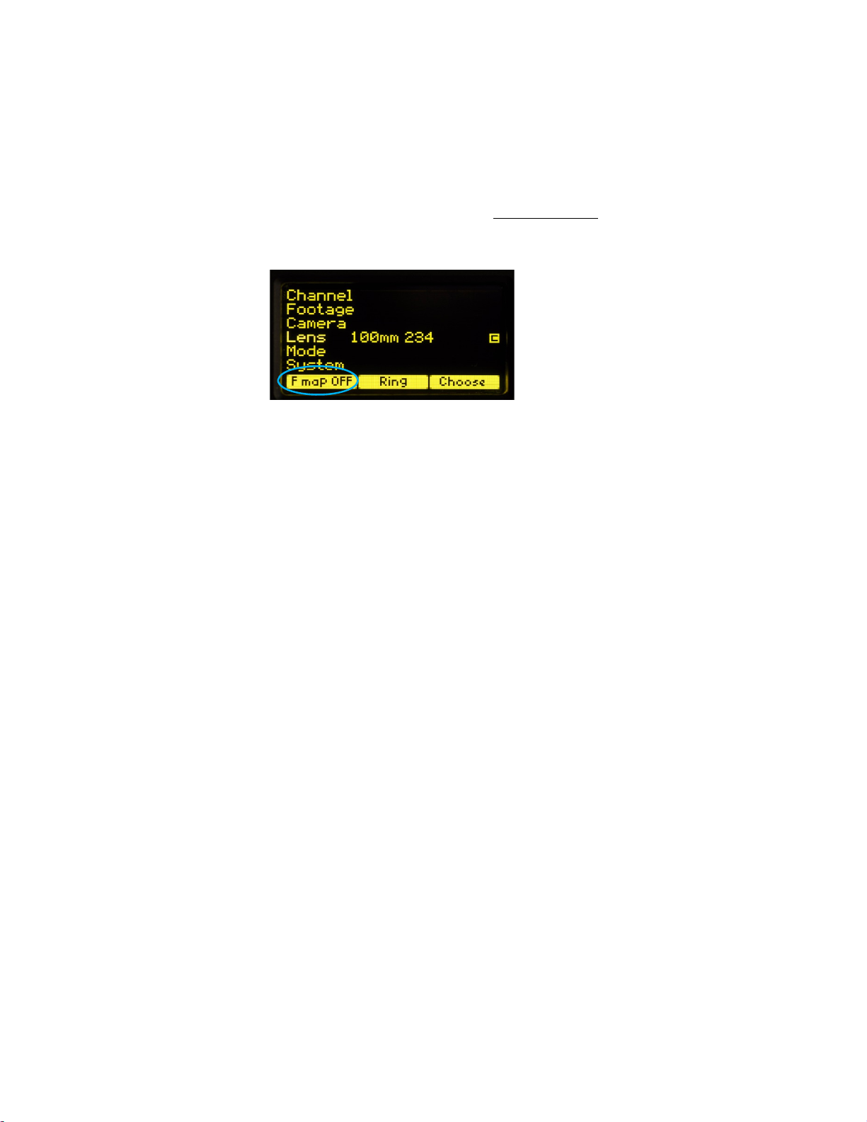
e. To use a blank focus marking ring, turn off the Focus mapping:
Press the Menu key.
Select Lens.
If the focal length and serial number of a lens appears to the right of “Lens”,
press Fmap OFF.
The HU3 is now ready for basic operation. The blank focus marking ring,
and iris marking strip can be used to mark lens calibrations.
f. Focus mapping eliminates the need to manually mark separate rings for each lens.
Data from the lens library is matched to pre-printed focus marking rings. This
makes process of lens changing quick and efficient. A detailed description of this
function showing the display screens is given in section III. To load focus data for a
lens and select a focus ring:
Press the Menu key.
Use the Nav key to select Lens.
Press Choose.
Select the lens location (All lenses, My List A…..)
Select the lens and press OK or the Enter key (the center of the Nav key).
Set the lens to infinity (as directed) and Enter/Next.
Press Ring and choose a focus ring with the desired near focus.
Install the same focus ring on the focus knob.
8
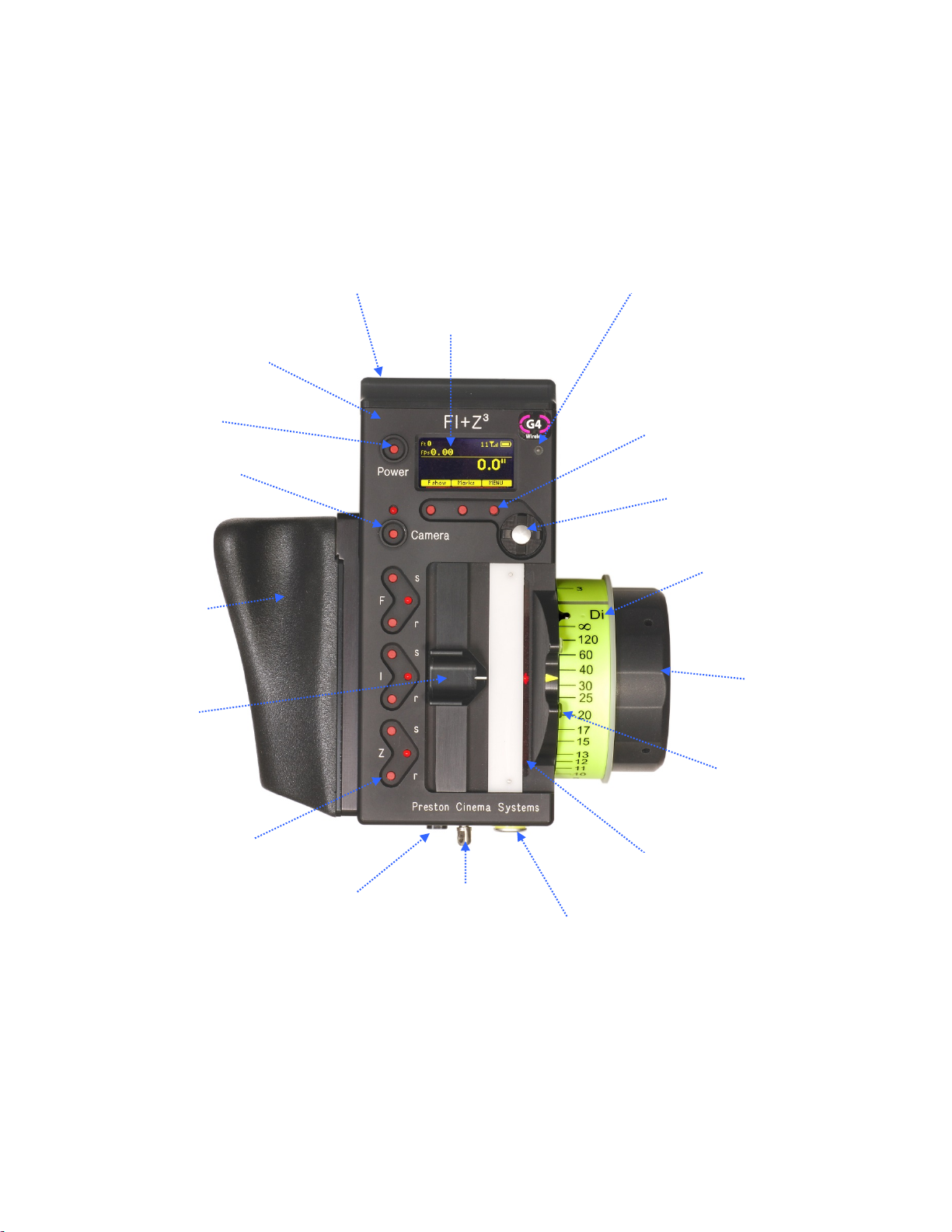
Hand Unit 3 Functions
Microwave Antenna Cover Ambient Light Sensor
OLED Dis
p
la
y
Pre-printed Focus
Marking Ring
Focus Knob with soft
Urethane Knob Grip
White LED’s (2) for
focus marking
ring. Brightness
adjusted with the
navigation key.
Molded Hand Grip
Zoom
Bargraph
Iris Slider
senses through
housing wall.
Splash Resistant
Housing
Hand Unit Power
Camera R/S with LED 4-way Navigation “Nav” Key
& Enter key (in center).
3 x Soft Keys
Neck Strap
Attachment point
Set/Reset switches
for Focus, Iris and
Zoom
LEMO receptacle
for
Remote Iris
Battery
Release

9
III. Hand Unit 3. Detailed Description
A. Grip Configurations.
1. The Hand Unit can be set-up with a molded Hand Grip for Focus and Iris control or with
the Hand Grip replaced by a flat cover to accommodate a bracket and Micro Force zoom
control.
2. Removing the Hand Grip. The Handgrip is removed to allow the bracket for the Micro
Force to be installed.
Press the Grip Release toward the HU3 housing (1).
Slide the Grip downward (2)
Replace the Grip with the cover (3).
Install the Micro Force bracket using the threaded hole at the rear of the
HU3.
HU3 with Hand Grip
and Quick Release Plate HU3 with Micro Force
and bracket 4336
(1)
(2) (3)

10
B. Set-Up and Operation
1. Main Display Screen. Press the Power Switch momentarily. The OLED display will
show the Main Display Screen :
2. Menu Screen Options. Press the MENU soft-key; the MENU screen appears.
3. Select a radio Channel to match that of the Motor Driver:
Press the right side of the NAV key to highlight the Channel number. Change to the
desired channel by pressing the top and bottom pads of the Nav key. The antenna icon
and bars indicate the presence and signal strength of MDR3 units on that channel.
4. To reset the Footage counter use the Nav key to highlight Footage, and press Clear.
Units are changed with the ft/m soft key. Change the movement type by pressing the right
side of the Nav key; 4, 3, and 2 perforation pull down are supported.
Lens Selection
Shows focus distance
in digital format
(Lens must be calibrated)
Shows focus knob
setting as bargraph
All functions are accessed through
the Menu key
Focus Ring Letterfootage Radio Channel
Signal Strength bars
Battery Charge
Main Display Screen
Menu Screen: Channel Selection

11
Film camera fps and shutter angle control are not supported with the MDR3, and the
corresponding menu items will not be active when the HU3 detects connection to an
MDR3 unit.
5. The Camera selection (Fig 5.1) provides for control of both camera speed and shutter
angle for those cameras supporting remote operation (MDR2 only). Pressing Choose
brings up the Manufacturers folders (Fig 5.2). Pressing Choose again brings up the list of
supported cameras (Fig 5.3).
Press the left pad of the Nav key to return back to the Camera selection. Press the Set-Up
key to bring up the camera Control menu (Fig 5.4). Use the Nav key to select and then
modify the camera speed and shutter angle. The List key appears when editing either a
camera speed or shutter angle. Pressing this key brings up tables containing commonly
used camera speeds and shutter angles (Fig 5.5, Fig 5.6).
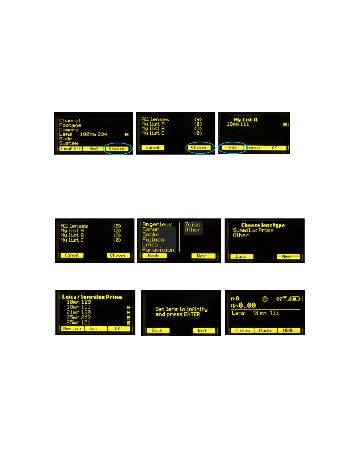
6. Selecting Lens with the Nav key (Fig. 6.1) allows lenses to be calibrated and their data
to be stored in the on-board library. The Focus Mapping software matches the witness
marks of calibrated lenses to the printed scales on the lens rings. The Ring key (Fig 6.1) is
used to match the installed focus ring letter (A – E).
Fig 5.1 Fig 5.2 Fig 5.3
Footage Counter menu Movement Selection
Fig 5.4 Fig 5.5 Fig 5.6
12
The Choose key brings up the list of folders containing lens data (Fig 6.2). The
All lenses
folder contains data on all of the lenses stored in the HU3 lens library. The Library stores
up to 255 lenses. Next brings up the contents of the selected folder (Fig 6.3).
The folders
My list A, B
, and
C
are used to store up to 15 lenses (3 screens) so that they
can be accessed quickly without having to scroll through the complete list. Pressing Add
allows a lens to be copied from the lens library to the
My list
folder (fig 6.3).
To use a lens from the library, choose a lens folder shown Fig 6.4. Using the Nav key
select the manufacturer (fig.6.5, the lens type (fig.6.6), and the lens (fig 6.7) and press
either OK or ENTER. Use the focus knob to set the lens to infinity, Fig 6.8, and press
NEXT/ENTER. The lens name now appears on the main screen (Fig. 6.9).
To calibrate a new lens:
Name the lens (focal length and serial number) and store it in the lens library.
Use the Edit function to calibrate the lens.
To name the lens, go to the Lens selection screen (FIG 6.1), press Choose, select All lenses
(Fig 6.4), select a manufacturer’s folder (Fig 6.5), and Lens Type (Fig 6.6).
Fig 6.4 Fig 6.5 Fig 6.6
Fig 6.7 Fig. 6.8 Fig. 6.9
Fig 6.1 Fig 6.2 Fig 6.3

13
Press the New Lens key (Fig 6.7) and you will be asked to select the focal length (Fig 6.10),
and Serial Number (Fig 6.11). When finished, press Next and the lens name (18mm s/n
123) appears in the lens type folder (Fig 6.12). Note that the lenses are automatically
sorted in ascending values of the focal length.
To calibrate the lens press Edit (Fig 6.12). Select Calibrate with the Nav key (Fig 6.13), and
press OK or ENTER).
After the lens focus ring is set to infinity (Fig 6.14), the display indicates the first of ten
calibration distances- close focus. There are two versions of this display screen, one for
lenses with linear focus mechanisms, and a second for lenses with non-linear focus.
Choosing a lens type automatically brings up the corresponding display screen.
The display screen for lenses with linear focus mechanisms allow the user to scroll up
and down with the Nav key (Fig 6.15, and 6.16).
The display screens for non-linear lenses show fixed distances for each calibration point
as shown in Fig. 6.18 – 6.20.
Fig 6.10 Fig 6.11 Fig 6.12
Fig 6.15 Fig 6.16 Fig 6.17
Fig 6.13 Fig 6.14
Fig 6.18 Fig 6.19 Fig 6.20

14
After the tenth point is entered (Fig. 6.17, 6.20), the lens description is shown to the right
of the Lens entry of the Menu (Fig. 6.21). The letter “c” to the right of the lens description
indicates that the lens has been calibrated. The main screen (Fig. 6.22) shows the lens
information.
To select the focus ring, →Menu (Fig 6.22) →Ring (FIG 6.21) and use the Navigation key ↕
to select either a ring (A – E) for metric or (Ai – Ei for imperial) (Fig. 6.23. The tables below
show the near focus distances for both the rings calibrated in imperial and metric units.
The printed labels Ai - Ei are pictured below. Note that the midpoint of each scale is about
twice the minimum focus distance. Although the ring can be chosen to cover the entire
focus range of the lens, it is often advantageous to choose the ring which covers the
minimum focus required for the actual shooting.
For example the Summilux 18mm lens has an 18” near focus, matching the Bi ring.
However if the closest distance required is 3’, only half of the knobs rotation would be
Ring Ai Bi Ci Di Ei
Near Focus 9” 18” 24” 36” 72”
Ring A B C D E
Near Focus .25m .50m .70m 1.0m 3.0m
Fig.23 Increasing the “throw” of the focus knob by choosing focus ring
minimum focus.
Fig. 6.21 Fig. 6.22 Fig. 6.23

15
used. Choosing the Di ring instead would make the entire rotation of the focus knob
available and double the spread of distances, dramatically improving the precision.
Note that any focus ring can be used with any calibrated lens.
7. The Mode (Fig. 7.1) has two functions. The first allows the four MDR motor channels,
focus, iris, zoom and auxiliary to be assigned to user-designated Hand Unit controls.
For example, in a multi-camera set-up, the focus knob of a single hand unit can be
assigned to focus, iris and zoom, allowing the focus knob to control the focus rings of up
to three separate lenses simultaneously.
The AUX channel of the MDR3 can be set-up to track the setting of the HU3 focus, iris, or
zoom, or the Focus/Iris control focus or iris, or the Radio Micro Force zoom. Use the
Navigation key to scroll down to AUX. Press the right side of the NAV key and a select the
source for the AUX channel to track. Figure 7.3 shows the AUX tracking the HU3 iris.
The second function of Custom Mode is to turn off one or more of the HU3 control
channels focus, iris, zoom or auxiliary. This is useful when using the HU3 in combination
with the Focus/Iris or Radio Microforce single channel units. Turning off the HU3 channel
will prevent the motor from changing from the setting of the single channel hand unit to
the setting of the HU3 if the signal from the single channel unit is lost.
Figure 7.4 shows the HU3 zoom channel set to Off, so if the signal from the Radio Micro
Force is lost, the motor will not revert back to the zoom setting of the HU3.
Fig. 7.1 Fig. 7.2
Fi
g
. 7.3 Fi
g
. 7.4
16
In situations where the lens setting must be controlled only by the single function hand
unit and not the HU3, the corresponding HU3 channel should be set to “Off”.
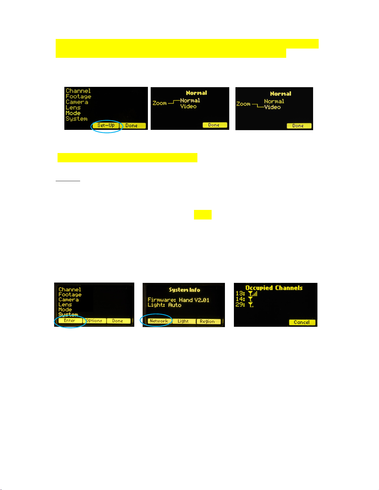
Zoom Mode Set-Up
(Zoom modes are only supported for the MDR2) To choose a Zoom Mode press the Set-Up
key (Fig. 7.5). The Normal Zoom mode (Fig. 7.6) means that the Hand Unit controls the
position of the zoom motor and this position is shown on the zoom bargraph display.
Limits can be set to the zoom range using the Set/Reset keys.
The Video Zoom Mode (Fig 7.7) is used when driving the internal motor of a video lens
using the analog zoom signal available at the MDR2 camera receptacle. In this mode, the
Hand Unit controls the velocity of the zoom motor, and the zoom bargraph shows the
velocity of the zoom, not its position.
8. The System Menu (Fig. 8.1) reports the installed firmware version, scans for other FI+Z
systems operating in the vicinity, sets-up the operating mode for the LED’s that illuminate
the focus rings, and specifies the focus distance units (imperial/metric).
Press the Enter key (Fig.1) to see the System Info screen (Fig. 8.2). Pressing the NETWORK
key initiates a scan of all HU3 channels. The Occupied Channels screen (Fig. 8.3) lists the
channels in use and their signal strength.
The Network scan function will only detect G4 devices; it will not detect Wi-Fi, Bluetooth,
frequency hopping devices, etc.
Press the Light soft key (Fig.8.2) to display the options for illuminating the focus ring.
The Auto option turns on the light automatically under dim conditions. The options may
be selected by using the Nav key to highlight the desired choice.
Fig. 8.1 Fig. 8.2 Fig. 8.3
Fig 7.6
Fig. 7.5 Fig. 7.7

17
The Region key (fig.3, 4) adjusts the output power of the microwave link to comply with
local regulations.
The OPTION (Fig. 8.6) selections consist of selecting distance units and knob direction.
Use the Navigation key to select the desired function. The default knob direction is CW.
Optional labels for the focus rings are available for CCW direction use.
9. The Zoom Bargraph indicates the position of the zoom when the zoom is in Normal
mode (See section 7. Operating Modes.) Note that the bargraph of the Digital Microforce is
not active when connected to the HU3, as the zoom position is only available when a
digital motor and Y cable are used. The zoom bargraph indicates the lens limits as
described in the next section.
10. Lens Limits (Fig. 10.1) can be set using the three groups of set/reset (s/r) keys. To
set a limit, move the motor to the first limit and press the set (s) key. While keeping the s
key pressed, move the motor to the second limit and release the skey. The limits are now
set and indicated by a lit LED in the corresponding group.
To remove a limit, press the reset key r.
The Zoom bargraph indicates the off-limits areas of the zoom range by two lit strips of
LED’s. The span of the allowed travel corresponds to the length of the un-lit LED’s.
Fig. 10.1
Fig. 8.4 Fig.8.5 Fig. 8.6

18
Lens limits can be used to lock a motor to a given position. This is done by setting a zero-
span, where the beginning and end of the range are the same point. To lock a motor,
position the motor to the desired point and press the set button twice.
11. CineTape Interface
CineTape units can be used to provide a distance reading that is displayed by the HU3
main display screen.
The CineTape interface (p/n 4742) connects the Remote Lemo receptacle of the CineTape
to the 4-pin Serial receptacle of the MDR3.
The CineTape data is displayed as soon as the interface is connected to the MDR3(Fig.
11.1).
Pressing the Fshow button switches the display from the remote distance measuring
device (Fig. 11.1) to a dual display (Fig 11.2) and finally to the default display (Fig.
11.3).
11. Software updates can be downloaded from the website
http://www.prestoncinema.com/downloads.html. To load an update into the HU3:
Install the boot loader program from the downloads page.
Make sure that the Hand Unit is not powered.
Connect the serial cable 4538 (serial connector to 4-pin Lemo) between the serial
port of the pc and the Serial receptacle on the rear cover of the HU3.
For laptops without a serial connector, use a USB to serial adapter.
To initiate the update, open the HU3 update program on your PC. While holding
the iris set button down, press the Power button of the HU3. Release all buttons.
The HU3 display will show the message “Ready to load”.
The display on the PC should now report that it has found a connection to the HU3
and ask whether you want to proceed with the update. Choose yes. After the
program has completed the update, you can remove the serial cable from the HU3.
Fig 11.1 Fig. 11.2 Fig. 11.3

19
12. Remote Iris Unit
A receptacle is provided on the bottom of the HU3 for an external, cable connected, iris
control. When the external iris control is connected, the slide control on the FIZ will be
disabled.
13. Focus Ring Light.Under low light conditions, two white LED’s will automatically
illuminate the Focus Ring.
To Change the brightness of the LED’s: tap the top/ bottom of the Nav key to
increase/decrease the brightness level.
IV. MDR3. Detailed Description
Fig. 12.1 Remote Iris Box p/n 4020
MDR3: Torque and Direction Switches Input/Output Connectors
MDR3: Channel Display & Switches - Top Channel Display & Switches - Side

20
The four channel Motor Driver (MDR3) is responsible for driving the motors, providing
control signals to the camera, and transferring camera operating data to the wireless
network through the transceiver module.
The MDR3 uses a lens calibration sequence to determine the mechanical limits of the zoom,
focus, and iris rings of the lens. This sequence is initiated whenever the Reset button on the
MDR is pressed, or whenever a motor is connected to the Motor Driver. Lens calibration
allows for precise, repeatable settings and also prevents accidental damage to the lens or
Digital Motor. An internal memory stores the positions of a calibrated lens for 12 hours
without external power.
To further protect the lens and driver electronics, the motors are electronically torque
limited and electronic motor stall protection is provided. In addition, self-resetting thermal
fuses protect all four channels. This insures that even in the event of improper calibration,
the motors will remain protected from overheating.
The LED status displays for motor torque and direction are activated by pressing any of
the red buttons. Change the Torque and Direction setting of a motor by pressing the
button adjacent to the corresponding connector. The bottom row of buttons controls the
torque and the upper row controls the direction.
At each press of the torque button, the LED color changes to indicate the
maximum torque level: blue minimum, green mid-level, red maximum.
Pressing the direction button changes the motor direction to correspond with the
Hand unit. The white LED indicates the status.
After approximately 4s from the last button press, the display will turn off.
Camera control signals are provided at the “Camera" receptacle of the MDR3.
The Microwave Transceiver is located in the lid of the MDR3. It provides wireless bi-
directional communication between the MDR3, Hand Unit, Focus/Iris units and other clients
in the wireless network. The lid also contains a voltage booster enabling MDR operation
over an input voltage range from 11 to 30 volts.
The wireless channels are selected by pressing the up/down channel switches located on
both the MDR3 top cover and side. There are 30 channels numbered 0 – 29 and are
backwards compatible with the MDR2 G4 units. Channels 30 – 59 use enhanced data
encoding and eliminate interference between closely spaced units.
The software controlling the MDR3 is updated through the USB receptacle and the USB cable
that connects the MDR to the USB receptacle of a PC or MAC (OS 10.5 or later). Software
updates are available either as a CD or download from our web site:
http://www.prestoncinema.com/downloads.html.
Table of contents
Popular Control System manuals by other brands


Cardin Elettronica
Cardin Elettronica ACD-148 manual

Pilz
Pilz PSS67 IO1 16FDI operating manual

Neptune Systems
Neptune Systems EnergyBar 6 Setup guide

hoxter
hoxter ABRA 6.1 Installation and operating instruction

Meccanica Fadini
Meccanica Fadini VIMARI 2316 instructions

Elsner
Elsner WS1 Color Installation and operation guide