PRESTON PRESSURE PS-625 User manual

PS-625
Pitot-Static/Air Data Tester
OPERATION AND MAINTENANCE
MANUAL
For Model PS-625
prestonpressure.com
Revision 1, September, 2020

PRESTON PRESSURE LLC
PS-625
USER AND MAINTENANCE MANUAL
TABLE OF CONTENTS
Page
Warranty and Liability Statement---------------------------------------------------- 2
1. General Information------------------------------------------------------------------- 3
1. Specifications ------------------------------------------------------------------ 3
2. Power Supply ------------------------------------------------------------------ 4
3. Vacuum and Pressure Pumps ------------------------------------------------ 4
4. Front Panel Layout------------------------------------------------------------- 5
5. Front Panel Description ------------------------------------------------------- 5
2. Theory------------------------------------------------------------------------------------- 7
1. Pneumatic Theory -------------------------------------------------------------- 7
2. Electronic Theory--------------------------------------------------------------- 8
3. Electrical Theory --------------------------------------------------------------- 8
3. Operation --------------------------------------------------------------------------------- 9
1. Error Codes ---------------------------------------------------------------------- 9
2. Pre-testing ----------------------------------------------------------------------- 9
3. Testing Aircraft Pitot System ------------------------------------------------- 10
4. Testing Aircraft Static System ------------------------------------------------11
5. testing the Aircraft Pitot and Static systems simultaneously ------------- 11
6. Using the E.P.R. Function ---------------------------------------------------- 12
4. Calibration Procedures ---------------------------------------------------------------- 13
5. Maintenance Repairs and Troubleshooting --------------------------------------- 17
1. Annual Maintenance ----------------------------------------------------------- 17
2. Troubleshooting ---------------------------------------------------------------- 17
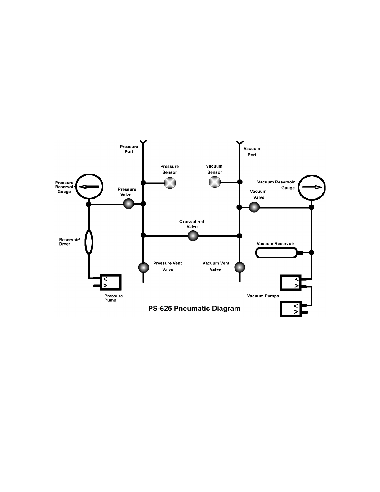
3. Pneumatic Diagram ------------------------------------------------------------ 19
6. Shipping and Storage ------------------------------------------------------------------ 20

2
WARRANTY AND LIABILITY STATEMENT
Preston Pressure LLC warrants its products against defects in workmanship and material under
normal, intended use for a period of two years from the date of purchase. The batteries are
warranted for a period of 90 days from the date of purchase. Valves are warranted for a period of
180 days.
Preston Pressure’s limit of liability shall be to repair or replace the product at their discretion.
Transportation shall be pre-paid to the Preston Pressure factory or authorized service facility.
Preston Pressure shall not be liable for any consequential damage expense.
This warranty shall be void if the product has been repaired or altered in any way that adversely
affects its performance or reliability. This warranty shall be void if the product has been subject
to abuse, misuse, contamination, negligence, accident, shipping damage, or improper operation.
Preston Pressure reserves the right, at its own discretion, to make changes in materials, designs,
finish, or specifications, without obligation to install or incorporate such changes in products
previously manufactured.
This warranty shall, at Preston Pressure’s option, become void if the ownership is changed,
unless the prior owner or proposed owner obtains written approval of continuation of coverage
prior to the change of ownership.
Preston Pressure reserves the right to revise this manual and to make changes to content from
time to time in the content thereof, without obligation to notify any person of such revision.
This device complies with part 15 of the
FCC Rules. Operation is subject to the following
two conditions: (1) This device may
not cause harmful interference, and (2) this
device must accept any interference received,
including interference that may
cause undesired operation.

3
CHAPTER 1
GENERAL INFORMATION
Description of the PS-625 Pitot-Static Air Data Test Box
The PS-625 Air Data, pitot-static test box is a digital display tester used to test aircraft altimeters,
airspeed indicators, pitot-static systems, and other vacuum and low-pressure devices. This test
box incorporates transducer sensor technology that is largely immune to the failures and costly
repairs associated with analog instruments.
The PS-625 is battery powered and portable. The vacuum and pressure sources are derived from
independent internal pumps, and each has its own reservoir. The tester can simulate pressure and
vacuum suitable for up to 65,000 feet and 650 Knots.
The PS-625 measures altitude in feet and meters. Airspeed is displayed in miles-per-hour,
kilometers-per-hour, MACH, and knots. Vacuum and pressure are also selectable in various units
of measure, including inches Hg, milliBars, mmHg, and Psia.
PS-625 SPECIFICATIONS
Digital Altimeter:
Display Range: -2000 to 65,000 feet (-610 to 19,800 meters)
Altitude Resolution: is in 1-foot increments and 1-meter increments
Accuracy: +/- 3 ft. at 0 ft., +/- 4 ft. at 10,000 ft., +/- 6 ft. at 20,000 ft., +/- 9 ft. at 35,000 ft., +/- 12 ft. at 40,000 ft.
+/- 19 ft. at 50,000 ft, +/- 25 ft at 60,000 ft.
Resolution of Other Measurement Units:
inHg (inches of mercury): 0.295 to 32.48 in increments of 0.003
mBar (millibars): 10 – 1100 in increments of 0.01
PSIA (pounds/square inch): 0.145 to 15.95 in increments of 0.01
mm HG (millimeters of mercury): 7.5 – 825 in increments of 0.01
Digital Airspeed:
Range: 18 – 650 Knots, 34 –1204 KPH, 21 – 748 MPH, 0.00 – .99 Mach
Resolution: 1 MPH, 1 KPH, 0.1 Knot, or 0.01 Mach
E.P.R. (engine pressure ratio): 0.07-6.00
Display Type: LCD Size: Altimeter and Airspeed: 99 x 24 mm
Physical Dimensions: 12”D X 15”W X 7”H (31x38x18 cm)
Temperature range: 32 degrees F to 120 degrees F (0 C to 50 C)
Weight: approximately 16 lbs (7 Kg)
Power Source:
External: 12 VDC (from a 110/220 VAC adapter)
Internal: 12 VDC (from internal rechargeable battery)
Other Features:
Leak test feature: 2 minutes, select-able down to 30 seconds
VSI (vertical speed indicator) to > 20,000 Ft./min
Vacuum and pressure pumps have brushless motors for longer life.

4
Power Supply
The PS-625 power supply consists of an external transformer with an output of 12 volts DC. This
supply is plugged into the round connector on the tester front panel. The transformer charges the
12-volt gel-cell lead acid battery internal to the PS-625. The battery enables the test box to be
used in a portable fashion, without a need for external power while the tester is in operation. The
test box can be used while it is charging and may be mounted in any position or angle.
A battery monitoring circuit is also incorporated. This will flash “Low Battery” on the display if
the battery voltage drops below approximately 9 VDC.
Vacuum and Pressure Pumps
The vacuum side uses two pumps, connected in series to achieve a vacuum level required for
high altitude tests. The pressure side uses one pump, which is sufficient to reach all the pressures
necessary for normal pressure tests.
The charge duration of the battery will vary, mostly depending on how long the vacuum is left
on. In order to obtain maximum charge durability, as well as extend pump and battery life,
it is recommended that the vacuum pump be left on only for the amount of time needed to
charge its reservoir, as shown in the gauge. Then the pump should be cycled on and off as
needed. When used properly, the user should be able to obtain several hours of operation
directly from the battery before needing to re-charge.
The pressure pump has a snap action switch that turns the pump OFF near 20 PSI, and ON below
or near to 15 PSI. The operator can simply leave the switch in the ON position and the switch
will automatically apply power to the pump to maintain pressure.
Vacuum and Pressure pumps should not be
allowed to run continuously. Toggle the
switches as needed to re-charge the reservoirs
as seen on the vacuum and pressure gauges.

5
FRONT PANEL LAYOUT
Front Panel Description
The front panel Altitude buttons function as follows:
The UNITS button is used to toggle between the various units of measurement available from
the vacuum/altimeter section. (Altitude in feet, Altitude in meters, mBar, mmHg, inHg, PSIA)
The EXIT button is used to exit out of the leak check mode.
The LEAK CHECK button is functional only when in the Altimeter mode. Pressing this button
will begin a 120 second timer, and the display will also show the gain or loss of altitude
experienced during the displayed time period. If the operator wishes to select a different length
of time, the Leak Check button may be pressed repeatedly, which will cause a reduction in the
timer counter in 30-second increments. The timer will not toggle above 120 seconds nor under
30 seconds. Pressing the Units button will start the counter and display the leakage.
The front panel Airspeed buttons function as follows:

6
The UNITS button is used to toggle between the various units of measurement available from
the pressure/airspeed section. (Airspeed in MPH, Knots, KPH, mBar, mmHg, inHg, PSIA, EPR)
NOTICE! The Mach airspeed must be measured at the altitude of 0 feet (sea level)!
The EXIT button is used to exit out of the leak check mode.
The LEAK CHECK button is functional only when in the Airspeed mode. Pressing this button
will begin a 120 second timer, and the display will also show the gain or loss of airspeed
experienced during the displayed time period. If the operator wishes to select a different length
of time, the Leak Check button may be pressed repeatedly, which will cause a reduction in the
timer counter in 30-second increments. The timer will not toggle above 120 seconds seconds nor
under 30 seconds. Pressing the Units button will start the counter and display the leakage.

7
CHAPTER 2
THEORY
The PS-625 test box consists of two vacuum pumps linked in series, one pressure pump,
reservoirs for the pressure and vacuum, a system of metering valves, and digital displays for
indicating altitude, airspeed, and various other pressure measurements, based on pressures sensed
in the sensor transducers.
Pneumatic Theory
Metering valves allow the operator to control the rate of flow of the air from the pressure or
vacuum sources, exiting out through the vacuum and pressure ports. The vent valves allow for
metering the produced vacuum or pressure back into the atmosphere. One crossbleed valve
permits the operator to isolate the pressure and vacuum sides, or to allow the balancing of
pressures, or even to reverse the normal flow of pressures.
The two round gauges allow the operator to monitor the level of pressure or vacuum that is
stored in the tester’s reservoirs. The switch corresponding to the pump for each reservoir should
be toggled to increase the reservoir’s level of vacuum or pressure as needed. For maximum
battery life, do not leave vacuum pump on continuously!
When the operator wishes to simulate an altitude, the Crossbleed, Vacuum, and Vacuum Vent
valves are gently closed. The vacuum pump is then energized until sufficient vacuum is in the
reservoir, as indicated on the Vacuum Reservoir Gauge. How much vacuum will be needed
depends on the desired altitude and is also affected by how long the tubing and lines are between

8
the test box and the altimeter. The vacuum and pressure reservoir gauges serve only as
general references of reservoir vacuum and pressure; they are not used in the actual
calibration of any instrumentation, and do not require calibration. Once sufficient vacuum
is obtained in the reservoir, the pump is turned off, and the Vacuum Valve is gently opened to
allow air to be suctioned into the system through the vacuum port. Once sufficient altitude
simulation is obtained, the Vacuum Valve is gently closed. Reduction in altitude is accomplished
by gently opening the Vacuum Vent Valve and allowing atmospheric air pressure to enter into
the lines.
If the operator needs to go to an altitude below atmospheric pressure, pressure must be
introduced into the pressure reservoir. Opening the Crossbleed Valve will enable pressure to
flow from the pressure reservoir to the altimeter. Open the Crossbleed valve, and then the
Pressure valve to pressurize the vacuum side.
Similarly, when airspeed is to be simulated, the Crossbleed, Pressure and Pressure Vent valves
will first be closed, until the operator establishes a pressure build-up in the pressure reservoir by
turning on the pressure pump. Then the Pressure Valve will be gently opened, allowing air
pressure to flow through the pressure port to the airspeed indicator. To reduce pressure, the
Pressure Vent valve is opened to leak the air pressure into the atmosphere.
Electronic Theory
The main circuit board of the PS-625 incorporates all the electronics for the altimeter and
airspeed indicators. The power switch is on the top of the circuit board. The 12 VDC power is
regulated to 9 VDC, 5 VDC, and 3.3 VDC.
The sensors used in the PS-625 test box are precision transducer sensors.
Warning: Even though the pressure sensors will not be damaged due to a high differential
pressure between the vacuum and pressure sides, damage can still occur in external
instruments connected to the test box.
Electrical Theory
One internal gel-cell lead-acid battery provides the power to the PS-625 test box. The battery is
charged via the power connector on the top panel of the test box. Full charging time is about 10
hours. The test box can be used while it is being charged.

9
CHAPTER 3
OPERATION
Preliminary Information
Prior to using the PS-625 tester, the user should become familiar with the unit by reading this
manual and operating the tester independently of any other attached devices.
The test procedures described in this manual are general in nature, for reference use only.
The operator may substitute these procedures with others, as applicable to the tests to be
performed, or according to other specific documentation.
Error codes display as follows:
Altitude displays “Too High” if it exceeds 65,500 feet.
“Inverse Pressure” will be indicated on the airspeed side if the static pressure exceeds the
pitot pressure by more than approximately 0.1 mbar. Due to its independent pressure and
static sensors, no damage will occur to the tester due to inverse pressure. However, damage
could occur to any system attached to the tester, therefore the warning is to alert the user of
the condition.
“Max Speed” will be indicated on the airspeed side if the pressure exceeds the equivalent of
650 knots. Due to independent pressure and static sensors, no damage will occur to the tester
due to this condition. However, damage could occur to any system attached to the tester,
therefore the warning is to alert the user of the condition.
Pre-Testing
Pre-test the static system of the PS-625 test box according to the following steps:
1. Ensure the PS-625 is not connected to any external hoses or devices.
2. Close the Vacuum Control, Vacuum Vent, Pressure Control, and Pressure Vent valves.
Open the Crossbleed valve.
3. Turn on the power, and then turn on the Vacuum Pump switch until the Vacuum
Reservoir gauge reads -15 inHG or greater vacuum.
4. Open the Vacuum Control valve to make the Altimeter section climb. This climb may be
done rapidly without damage to the sensor.
5. When the Altimeter reads at least 18,000 feet, gently close the Vacuum Control valve.
6. Wait for 2 minutes or more for the internal pressure to stabilize. Note: a rapid climb will
not damage the tester. However, the internal tubing needs time to contract due to the
applied vacuum, and this will give the appearance of a small leak for the first 2 minutes
or more.
7. Perform a leak check to monitor the leak rate. Verify that the PS-625 does not leak
exceeding 100 feet per minute. Write down the leak rate for future reference. (Subtract

10
this value from the total leak rate when testing the aircraft, to arrive at the aircraft’s leak
rate.)
8. Open the Vacuum Vent valve to bring the test box back to ground (ambient) pressure.
Pre-test the pressure system of the PS-625 test box according to the following steps:
1. Turn on the power to the PS-625.
2. Ensure the PS-625 is not connected to any external hoses or devices.
3. Close the Vacuum Control, Vacuum Vent, Pressure Control, Crossbleed valve, and
Pressure Vent valves.
4. Turn on the Pressure Pump switch until the Pressure Reservoir gauge reads 10 PSI or
more.
5. Open the Pressure Control valve to make the Airspeed section climb. This climb may be
done rapidly without damage to the sensor.
6. When the Airspeed reads at least 300 knots, gently close the Pressure Control valve.
7. Wait for about 15 seconds for the internal pressure to stabilize. Activate the leak check
function to monitor the leak rate. Verify that the PS-625 does not leak exceeding 2 knots
per minute. Write down the leak rate for future reference. (Subtract this value from the
total leak rate when testing the aircraft, to arrive at the aircraft’s leak rate.)
8. Open the Pressure Vent valve to bring the test box back to ground (ambient) pressure.
Testing Aircraft Pitot System Only
NOTICE! The Mach airspeed must be measured at the altitude of 0 feet (sea level)!
1. Turn on the power to the PS-625.
2. Connect the Pressure Port to the aircraft Pitot system.
3. Close Pressure Control, Pressure Vent, and Crossbleed valves. Open Vacuum vent valve.
4. Turn Pressure Pump switch on until the Pressure Reservoir indicates 10 PSI or more.
5. Gently open the Pressure Control valve until desired speed(s) are achieved.
6. Compare the airspeed of the PS-625 box to the airspeed indicated in the aircraft.
7. Go to approximately 75% of the maximum airspeed of aircraft indicator (or the speed
specified by the manufacturer). Close the Pressure Control valve and after allowing a few
seconds for stabilization, perform a leak check. The pitot system should not leak more
than two knots per second, plus the leakage previously noted in the pressure system pre-
test.
8. Gently open the Pressure Vent valve to return the pitot pressure to ambient pressure.
Testing of Aircraft Static System (independent from the pitot system)
Note: If the previous pitot system test indicated an excessive leak, do not proceed until that leak
is repaired. Damage to aircraft airspeed indicator could result.
1. Turn on the power to the PS-625.
2. Disconnect the static line to the airspeed indicator, and cap the line.

11
3. Connect the Vacuum Port to the aircraft static port. Set the aircraft altimeter to 29.92
inHg (1013.3 mB).
4. Close Vacuum Control, Vacuum Vent, Pressure Control, and Pressure Vent valves. Open
Crossbleed valve.
5. Operate the Vacuum Pump switch until a desired level of vacuum is seen on the Vacuum
Reservoir gauge (generally -15 to -20 inHG). Turn Pressure Pump switch on until the
Pressure Reservoir indicates 10 PSI or more.
6. Gently open the Vacuum Control valve to cause the altitude to climb.
7. DO NOT exceed the climb rate of the aircraft VSI indicator, or the airspeed indicator
limits. The VSI is a very delicate instrument.
8. Climb to the desired altitude(s) per the test to be performed.
9. Close the Vacuum Control valve, and after allowing a few seconds for stabilization,
compare the aircraft altimeter with the test box.
10. When at the appropriate altitude (generally 18,000 feet) perform a leak check. If the static
system shows leakage, be careful to not exceed the VSI rate. Be prepared to open the
Vacuum Control valve if needed, to prevent excessive VSI indication.
11. Gently open the Pressure Vent valve to return the system pressure to ambient pressure.
Do not exceed the VSI or airspeed indicator limits.
12. Re-connect airspeed indicator static line and do a leak check test.
Note: if an altitude lower than ambient pressure is desired, do steps 1-4 above. Gently open
the Pressure Control valve to pressurize the system, thereby causing the altimeter to decrease
in altitude. Open the Vacuum Vent valve to return to ambient pressure.
Testing the Aircraft Pitot and Static systems simultaneously
Note: First ensure pitot system does not leak by performing Pitot system test on page 14.
1. Turn on the power to the PS-625.
2. Connect the Vacuum Port to the aircraft static port, and the Pressure Port to the aircraft
pitot port. Set the aircraft altimeter to 29.92 inHg (1013.3 mB).
3. Close Vacuum Control, Vacuum Vent, Pressure Control, and Pressure Vent valves. Open
Crossbleed valve.
4. Operate the Vacuum Pump switch until a desired level of vacuum is seen on the Vacuum
Reservoir gauge (generally -15 to -20 inHG). Turn Pressure Pump switch on until the
Pressure Reservoir indicates 10 PSI or more.
5. Gently open the Vacuum Control valve to cause the altitude to climb.
6. DO NOT exceed the climb rate of the aircraft VSI indicator, or the airspeed indicator
limits. The VSI is a very delicate instrument.
7. Climb to the desired altitude(s) per the test to be performed.
8. Close the Vacuum Control valve, and after allowing a few seconds for stabilization,
compare the aircraft altimeter with the test box.
9. When at the appropriate altitude (generally 18,000 feet) perform a leak check. If the static
system shows leakage, be careful to not exceed the VSI rate. Be prepared to open the
Vacuum Control valve if needed, to prevent excessive VSI indication.

12
10. To display an airspeed, close Crossbleed valve and gently open Pressure valve until
desired airspeed is indicated. Close Pressure valve.
11. To return system to ambient pressure, ensure Crossbleed valve is open. Then gently open
the Pressure Vent valve to return the system pressure to ambient pressure. Do not
exceed the VSI or airspeed indicator limits.
Note: if an altitude lower than ambient pressure is desired, do steps 1-4 above. Gently open
the Pressure Control valve to pressurize the system, thereby causing the altimeter to decrease
in altitude. Open the Vacuum Vent valve to return to ambient pressure.
Using the E.P.R. function
The EPR function is used to test engine pressure ratios. This ratio is the mathematic result of:
High Pressure/Low Pressure. The PS-625 test box will display the low pressure, the high
pressure (both in PSI), and the resulting EPR. To use the EPR function, proceed as follows:
1. Turn on the test box.
2. Close all of the valves, including the Crossbleed valve.
3. Connect the Vacuum port to the low pressure to be tested.
4. Connect the Pressure port to the high pressure to be tested.
5. Cycle through the Units on the Airspeed side until in the EPR mode. Read the EPR
values displayed.
Note: Do not exceed 25 PSI on the high pressure side, to avoid sensor damage.

13
CHAPTER 4
CALIBRATION
The recommended calibration interval for the PS-625 test box is one year. If at any time
during regular use the unit becomes unreliable or out of correct operating calibration, it must be
repaired and/or re-calibrated before continuing its use.
The calibration factors are stored in the microcontroller’s EEPROM memory. This memory does
not need battery back-up. The calibration will not be lost if the unit’s batteries are disconnected
or replaced.
Calibration Procedures
The PS-625 test box is easy to calibrate. There are 7 set points used in the calibration of the
altimeter side. Calibrating at multiple setpoints enables the altimeter to have a greater degree of
accuracy, allowing it to self-correct to the nearest calibrated set point.
The altimeter side should normally be calibrated first, as the airspeed side reads the static
pressure through the altimeter circuitry. However, if the altimeter side has been tested and found
satisfactory, the airspeed side can be calibrated at any time.
1. Apply power to the PS-625 and allow unit to warm up for a minimum of 10 minutes.
2. Gently close the Vacuum Control valve, Vacuum Vent valve, and Crossbleed valve.
3. Connect a known altitude pressure standard to the Vacuum Port.
4. Set the PS-625 altimeter measurement units to read in mbar by pressing the Units button.
5. Press the Exit and Leak Check buttons simultaneously. The display will change to:
Enter Cal mode?
N Y
Press the Exit button to exit the calibration mode, or the Leak Check button to enter.
6. At this point the display will read:
Go to 0 Feet
Next
Apply a pressure equivalent to 0 feet and press the Units button to continue.
The display will now read:
XXX Ft
In YY
Where XXX is the sensed altitude and YY is the internal correction factor currently stored in the
calibration memory.

14
If the displayed altitude is lower than the standard, press the Exit button as needed to raise the
altitude to be equivalent to the standard.
If the displayed altitude is higher than the standard, press the Leak Check button as needed to
lower the altitude to be equivalent to the standard.
As the altitude is adjusted, note that the displayed correction factor also changes. Use this to fine-
tune the altitude as close as you can to the standard.
When the PS-625 altitude matches the standard as close as possible, press the Units button to
proceed to the next calibration level. Repeat the same adjustment at each requested altitude point.
The displayed altitude accuracy tolerance must be within these maximum error values:
+/- 3 ft. at 0 ft.
+/- 4 ft. at 10,000 ft.
+/- 6 ft. at 20,000 ft.
+/- 9 ft. at 35,000 ft.
+/- 12 ft. at 40,000 ft.
+/- 19 ft. at 50,000 ft.
+/- 25 ft. at 60,000 ft.
After the altitude is calibrated, adjust the VSI. After the VSI correction is entered, the calibration
mode will store all the entered values and return to normal operation.

15
Airspeed Calibration Procedures
1. If not already powered, apply power to the PS-625 and allow the unit to warm up for a
minimum of 10 minutes.
2. Gently close the Pressure Control valve, Pressure Vent valve, and Crossbleed valve.
3. Connect a known pressure standard to the Pressure and Vacuum Ports.
4. Press the Units button to set the airspeed measurement units to read in mbar.
5. Press the Exit and Leak Check buttons simultaneously. The display will change to:
Enter Cal mode?
N Y
Press the Exit button to exit the calibration mode, or the Leak Check button to enter.
6. At this point the display will read:
Goto 50 Knots
Next at 0 Feet
Apply a pressure of 0 feet at the Vacuum port and a pressure of 50 Knots at the Pressure
port. Then press the Units button to go to the next screen.
7. The display will show:
X.X Knots
Enter YY
Where X.X is the airspeed in knots and YY is the internal correction factor currently stored in
the calibration memory.
If the displayed airspeed is lower than the standard, press the Exit button as needed to
incrementally raise the airspeed to be equivalent to the standard.
If the displayed airspeed is higher than the standard, press the Leak Check button as needed to
incrementally lower the airspeed to be equivalent to the standard.
As the airspeed is adjusted, note that the displayed correction factor also changes. Use this to
fine-tune the airspeed as close as you can to the standard.
When the PS-625 airspeed matches the standard as close as possible, press the Units button to
save the calibration and exit back to the mBar mode.
Note: The airspeed has only one calibration point.
8. When a satisfactory calibration is obtained at this test point, go through various test points to
verify that the display is within acceptable parameters.

16
The displayed airspeed accuracy tolerance must be within these values:
+/- 1.0 knots @ 20 knots
+/- 0.5 knots @ 50 knots to 650 knots
If the accuracy is out of the allowed tolerance, either adjust the calibration again or make a
correction chart for the operator to reference.
Calibration of Reservoir Gauges
The reservoir gauges are for reference only, and do not need calibration. The operator merely
references these gauges as an indication of how much reserve pressure or vacuum there is in the
reservoirs, and as a guide to know when to turn on the pump(s).

17
CHAPTER 5
MAINTENANCE REPAIRS AND TROUBLESHOOTING
Note: Refer to the Theory of Operation section as a reference on how the various systems
function.
Annual Maintenance
The following annual maintenance is recommended:
1. Check color of beads in air reservoir/dryer. Change if pink or clear. The dryer is a common in-
line dryer used in small air compressor systems. A new dryer can be purchased from Preston
Pressure, or an internet search for “mini inline desiccant air dryer” may lead to an alternate
source.
2. Feel fuse to verify tightness. If the fuse feels loose, remove the fuse, squeeze fuse clip slightly
and re-install fuse.
3. Tug on motors to verify motors are mounted tightly. If play is noticed, disconnect tubing,
batteries and connectors. Remove bottom assembly panel by removing the screws holding the
bottom assembly. Tighten the motor mount screws and re-assemble.
4. Verify vacuum reservoir tank is mounted tightly.
5. Verify electrical connectors are seated completely.
6. Verify battery holding clamps are tight.
7. Verify switches and valves on front panel are mounted tightly.
8. Test for leaks.
9. Perform calibration checks and re-calibrate if necessary.
Troubleshooting
Refer to the following chart of symptoms, causes, and repair comments:
SYMPTOMS
POSSIBLE CAUSES
COMMENTARY
Display shows garbage or
freezes at the beginning
display.
Microcontroller had a
power brown-out or there is
a low voltage condition.
1.Turn off unit for 10
seconds before powering up
again.
2. Re
-
cycle power switch. If

18
problem occurs frequently,
it may be caused by a loose
or dirty internal connector.
Check connectors to battery
and circuit board. Also
check for
a
loose fuse.
Display never finishes
initializing
1. Tester is being operated
in conditions that are
excessively cold (below
freezing).
2. Low battery
3. If occurring on airspeed
side, it is not receiving
static pressure from vacuum
sensor.
1. Operate the tester in a
warmer environment.
2. Re-charge battery.
Decoder flashes “LOW
BATTERY”
Battery voltage is low
1. Connect charger.
2. If voltage is still low, or
charge is rapidly lost, there
is a defective battery.
3. The fuse may be blown or
loose on the
main
board.
Motors do not work
1. Low battery voltage
2. Bad fuse
3. Bad switch or connectors
4. Bad motor(s)
1. Replace fuse
2. Check switches and
connectors.
3. Replace bad motor(s)
Displays do not turn on 1. Low voltage
2. Bad fuse
3. Bad wiring or connector
4. Bad power switch
5. Bad voltage regulator
1. Connect charger. If
battery voltage remains low,
or charge is rapidly lost,
there is a defective battery.
2. Replace fuse
3. Replace power switch.
4. Replace voltage regulator.
Battery does not take a
charge
1. Bad battery
2. Bad power charger
3. Bad fuse
4. Bad power supply circuit
1. If battery charge is
rapidly lost, there is a
defective battery.
2. Replace power charger
3. Replace bad fuse
Unit will not vacuum up to
65,000 feet
1. Leak in internal hoses or
plumbing connectors
2. One motor is weak or
inoperative
1. Troubleshoot plumbing to
find leak(s)
2. Replace defective motor
19
Table of contents
Other PRESTON PRESSURE Test Equipment manuals


Popular Test Equipment manuals by other brands


Redtech
Redtech TRAILERteck T05 user manual

Venmar
Venmar AVS Constructo 1.0 HRV user guide

Test Instrument Solutions
Test Instrument Solutions SafetyPAT operating manual

Hanna Instruments
Hanna Instruments HI 38078 instruction manual

Kistler
Kistler 5495C Series instruction manual

Waygate Technologies
Waygate Technologies DM5E Basic quick start guide

StoneL
StoneL DeviceNet CK464002A manual

Seica
Seica RAPID 220 Site preparation guide

Kingfisher
Kingfisher KI7400 Series Training manual

Kurth Electronic
Kurth Electronic CCTS-03 operating manual

SMART
SMART KANAAD SBT XTREME 3G Series user manual

Agilent Technologies
Agilent Technologies BERT Serial Getting started