manuals.online logo
Brands
  1. Home
  2. •
  3. Brands
  4. •
  5. Festo
  6. •
  7. Controllers
  8. •
  9. Festo VPPI S1BT Series User manual

Festo VPPI S1BT Series User manual

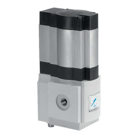
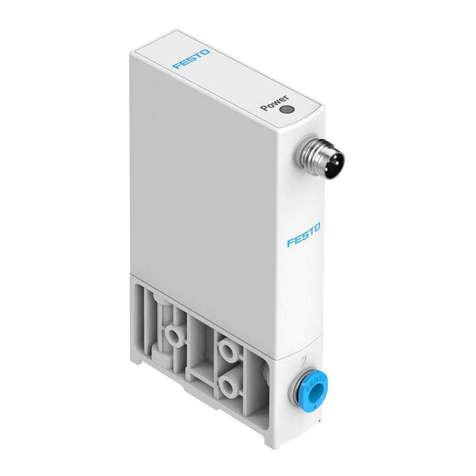
VPPI-...-S1/-S1BT
Proportional-pressure regulator
Festo SE & Co. KG
Ruiter Straße 82
73734 Esslingen
Deutschland
+49 711 347-0
www.festo.com
Operating instructions
8156715
2021-11a
[8156717]
Translation of the original instructions
© 2021 all rights reserved to Festo SE & Co. KG
Bluetooth®, IO-Link® are registered trademarks of the respective trademark
owners in certain countries.
1Applicable documents
Document Product Contents
Manual Proportional-pressure regulator
VPPI-...-LK/-PT-S1
IO-Link interface/I-Port inter-
face, Parameterisation
Manual Proportional-pressure regulator
VPPI-...-A.../-V...-S1BT
Bluetooth interface, Parame-
terisation with plug-in for the
Festo Automation Suite
Manual Bus node CTEU-... Parameterisation with the aid
of the bus node in use
Test report1) Proportional-pressure regulator VPPI-...-T Determined accuracies
1) Only if the test report was selected in the configurator when ordering the product. Accessible on the Festo
website by entering the product key.
Tab. 1: Applicable documents
All available documents for the product è www.festo.com/sp.
2 Product labelling
–Observe the specifications on the product.
Warning symbol
The following warning symbol is on the product VPPI-...-S1BT:
Symbol Meaning
Mechanical overload can cause the valve to malfunction. Under certain circum-
stances, this malfunction will cause permanent energisation of the coils resulting in
a hot surface.
Tab. 2: Warning symbol
3 Safety
3.1 Safety instructions
–Only use the product in original status without unauthorised modifications.
–Only use the product if it is in perfect technical condition.
–Take into consideration the ambient conditions at the location of use.
–Before working on the product, switch off the power supply and secure it
against being switched on again.
–The product variants VPPI-...-A.../-V...-S1BT have a Bluetooth interface that is
permanently active. Fuse protection is therefore required.
3.2 Intended use
The proportional-pressure regulator is intended to regulate a pressure propor-
tional to a specified setpoint value.
The product may generate high frequency interference, which may require inter-
ference suppression measures in residential areas.
4 Additional information
–Contact the regional Festo contact if you have technical problems
è www.festo.com.
–Accessories and spare parts è www.festo.com/catalogue.
5 Product overview
5.1 Function
A built-in pressure sensor records the pressure at the working port and compares
this value with the setpoint value. In the event of deviations between the setpoint
value and actual value, the valve regulates until the outlet pressure has reached
the setpoint value.
VPPI -...- 3 -...
(normally closed)
VPPI -...- 4 -...
(normally open)
Tab. 3: Pneumatic Circuit Symbol
5.2 Product design
17
2
3
4
56
Fig. 1: Product design (example VPPI)
1
LEDs control behaviour (not with
VPPI-...-PT-S1)
2
Operating keys control behaviour (not
with VPPI-...-PT-S1)
3
Plug M12
4
Working air port (2)
5
Exhaust air port (3)
6
Compressed air port (1)
7
LED for operating status (not with
VPPI-...-PT-S1)
6Transport and Storage
–Store the product in a dry, UV- and corrosion-protected environment.
–Ensure short storage times.
7 Assembly
7.1 Assembly
7.1.1 Linkage of valves
Up to 5 valves can be linked. The connecting kit VAME-P18-K-P5 is required for the
linkage è www.festo.com/catalogue.
The connecting kit consists of 2 square nuts, 2 socket head screws and an O-ring.
1. Remove the plug screw and sealing material from the duct (1).
2. Insert the O-ring into the duct (1) between 2 valves.
3. Connect the valves on the bottom using socket head screws and square nuts.
Tightening torque: 1.2 ± 0.2 Nm
4. Connect the valves at the rear using socket head screws and square nuts.
Tightening torque: 1.2 ± 0.2 Nm
7.1.2 Creating pressure zones
For separating pressure zones, connect the compressed air supply to both ends of
the valve manifold.
The plug screw can be left in the duct (1) of the valve for pressure zone separa-
tion.
Plug screws VAME-P18-BP-G18-P5 for the duct (1) can also be ordered as accesso-
ries è www.festo.com/catalogue.
•Screw the plug screw into the duct (1) of the selected valve. Screw in the plug
screw until it is flush with the surrounding surface.
7.2 Mounting
7.2.1 Mounting via bottom of valve
Fig. 2: Mounting via bottom of valve with M4 screws/M4 screws and square nuts
7.2.2 Mounting via valve side surface
Fig. 3: Mounting via side with internal M4 screws/M4 through screws
7.2.3 Mounting on H-rail
Fig. 4: Individual valve
7.3 Mechanical installation
1. Make sure there is sufficient space for the connecting cable and tubing con-
nections.
ÄThis will prevent kinks from forming in the connecting cables and the
tubing.
2. Place the valve as close to the consumer as possible.
ÄThis improves control precision and reduces response times.
8 Installation
8.1 Pneumatic installation
Valves for standard operation (overpressure)
1. Attach the tubing to the connections:
–Compressed air (1)
–Working air (2)
2. Fit a silencer at the exhaust air connection (3) or provide for ducted exhaust
air.
Valves for vacuum operation or combined vacuum and overpressure operation
(VPPI-...-1V...H-...)
1. Attach the tubing to the connections:
–Vacuum (3)
–Working air (2)
2. Connect a compressed air supply to port (1) or mount a silencer to protect the
valve from coarse dirt particles.
8.2 Electrical installation
WARNING
Risk of Injury due to Electric Shock.
• For the electric power supply, use only PELV circuits that ensure a reliable
electric disconnection from the mains network.
•Observe IEC 60204-1/EN 60204-1.
• The unit must be powered by a power source that fulfils the requirements of an
energy-limited circuit in accordance with IEC 61010-1/EN 61010-1.
1. If a screened cable is used: earth the shield at the cable end away from the
valve.
2. Install electrical connecting cable without squeezing, kinking or stretching.
3. Tighten the electrical connecting cable onto plug M12. Tightening torque:
maximum 0.3 Nm
Connection Pin Allocation Wire colour1)
NEBU-M12...
Analogue IO-Link/I-Port
1 + 24 V DC 24 V DC (UEL/SEN)BN
2 Setpoint value (–) 24 V DC (UVAL)WH
3 GND 0 V DC (UEL/SEN)BU
4 Setpoint value
(+)/PWM
C/Q
Data communication
BK
5 Actual value output
–based on pin 2 "set-
point value (-)" for
type VPPI-...-V1-...
–based on pin 3
"GND" for
VPPI-...-A4-...
0 V DC (UVAL)GY
1) Colour code in accordance with IEC 60757:1983-01
Tab. 4: Pin allocation for plug M12, 5-pin, A-coded
9 Commissioning
Requirements:
–The valve must be assembled.
–The pneumatic and electrical installation must be complete and tested.
1. Check operating conditions and critical limits è 12 Technical data.
2. Switch on the power supply.
3. Switch on the compressed air supply.
4. If necessary, adjust the control response of the valve.
9.1 Commissioning VPPI-...-A.../-V...-S1
Control response
The control response of the valve can be set using the operating buttons on the
top of the valve è Fig. 1. The symbols above the operating buttons represent the
control response of the valve.
Setting the control response
1. Hold middle button for 3 s.
2. Select the control response with the arrow keys.
ÄThe LED under the symbol of the selected control response lights up.
3. Confirm the control response with the middle key.
Symbol Application recommendation
Designed for flow rate applications.
Standard preset for all applications. Optimised for closed volumes from
100 ml to approx. 750 ml.
Optimised for closed volumes of ³ 750 ml. Less suitable for volumes of
< 500 ml.
Tab. 5: Control response
9.2 Commissioning VPPI-...-A.../-V...-S1BT
The product variants VPPI-...-A.../-V...-S1BT have a Bluetooth interface for param-
eterisation. Parameterisation takes place via the Festo Automation Suite plug-in
and is described in the manual VPPI-...-A.../-V...-S1BT è 1 Applicable documents.
The Bluetooth interface is permanently active. The Bluetooth connection must
therefore be secured against unauthorised access.
• Protect the Bluetooth connection with a password.
The password function in the plug-in in the Festo Automation Suite is described in
the manual VPPI-...-A.../-V...-S1BT è 1 Applicable documents.
9.3 Commissioning VPPI-...-LK/-PT-S1
The product variants VPPI-...-LK/-PT-S1 have an IO-Link/I-Port interface for param-
eterisation and process data transmission. Parameterisation and the required
configuration files are described in the manual VPPI-...-LK/-PT-S1 è 1 Applicable
documents.
10 Malfunctions
10.1 Diagnostics
The following table describes the diagnostics with the LED operating status è Fig.
1, [7].
The product variants VPPI-...-PT-S1 with I-Port interface do not have LEDs. Infor-
mation on the operating status is displayed by the connected CTEU bus node
è Documentation of the CTEU bus node.
LED Status and meaning
LED lights green:
–The operating voltage is present and within the permissible range.
–Setpoint signal lies within the permissible range (0 … 10.8 V or 2.5 … 20.5 mA).
LED lights red:
–Working temperature is too high.
–Valve is in temperature shut-off.
LED flashes red:
–Supply voltage is too high
LED flashes alternately red and green in the ratio 1:1:
–Analogue setpoint value is too high.
–Cable break setpoint input
LED flashes alternately red and green in the ratio 1:5:
–Temperature is critical
–Power reduction active
LED is off:
–No operating voltage.
–The operating voltage is below the permissible range (< 20.4 V).
LED flashes green at a ratio of 1:9, VPPI-...-LK-S1:
–IO-Link connected
LED flashes green at a ratio of 1:1, VPPI-...-S1BT:
–Bluetooth connected
Tab. 6: Operating status LED
10.2 Fault Clearance
Error description Cause Remedy
Valve does not respond. Operating voltage not applied. Check the operating voltage
connection.
No setpoint voltage. Check the controller and con-
nection.
Working temperature is too
high. Valve is in temperature
shut-off.
Switch off the valve, let it cool
down and restart.
Reduce ambient temperature
and / or temperature of
medium.
Valve normally open:
The working pressure at (2)
falls to the level at (3) (ambient
pressure or vacuum).
Cable break setpoint input Check connection to setpoint
generator.
Replace supply cable.
Valve normally closed:
The working pressure at (2)
deviates upwards or down-
wards from the setpoint value
(working pressure is neither
pressurised nor exhausted).
Cable break setpoint input Check connection to setpoint
generator.
Replace supply cable.
Setpoint value not reached. Input pressure at (1) is too low. Increase input pressure at (1).
Maintain permissible maximum
operating pressure è 12 Tech-
nical data.
Tab. 7: Fault Clearance
11 Disassembly
1. Specify setpoint value 0 bar (0 MPa).
2. Switch off compressed air supply.
3. Switch off operating voltage.
4. Remove electrical connecting cables.
5. Remove compressed air lines.
6. Dismantle the product.
12 Technical data
An individual test report is created for products of the variant VPPI -...- T. This
test report can be found in the Support Portal (FoX) by entering the product key
www.festo.com/sp.
General technical data
Valve function 3-way proportional-pressure regulator
Mounting position any
Product weight [g] 370
Approvals RCM
KC
Materials
Seals HNBR
Housing Reinforced PA
Tab. 8: General technical data
Operating and ambient conditions
Ambient temperature [°C] 0 … 50
Storage temperature [°C] –20 … +70
Temperature of medium [°C] 0 … 50
Degree of protection IP65
Operating medium Compressed air in accordance with
ISO 8573-1:2010 [7:4:4]
Inert gas
Information on the operating
medium
lubricated operation not possible
Climate class in accordance
with EN 60721
3k3
Nominal operating altitude < 3000 m above MSL
Vibration resistance/shock resistance (in accordance with IEC 60068)
Note Explanation of the severity levels (SL) è Tab. 10 Type
of severity level (SL)
Vibration (part 2-6) Individual valve fastened with screws: SL2
Individual valve on H-rail: SL1
Linkage of max. 3 valves with lateral screw mounting:
SL2
Linkage of max. 5 valves with lateral screw mounting:
SL1
Shock (part 2 – 27) Individual valve fastened with screws: SL2
Individual valve on H-rail: SL1
Linkage of max. 3 valves with lateral screw mounting:
SL2
Linkage of max. 5 valves with lateral screw mounting:
SL1
Tab. 9: Operating and ambient conditions
Type of severity level (SL)
Vibration load
Frequency range [Hz] Acceleration [m/s2]Deflection [mm]
SL1 SL2 SL1 SG2 SL1 SL2
2 … 8 2 … 8 – – ±3.5 ±3.5
8 … 27 8 … 27 10 10 – –
27 … 58 27 … 60 – – ±0.15 ±0.35
58 … 160 60 … 160 20 50 – –
160 … 200 160 … 200 10 10 – –
Shock load
Acceleration [m/s2]Duration [ms] Shocks per direction
SL1 SL2 SL1 SL2 SL1 SL2
±150 ±300 11 11 5 5
Continuous shock load
Acceleration [m/s2]Duration [ms] Shocks per direction
±150 6 1000
Tab. 10: Type of severity level (SL)
Characteristic pneumatic values
Product type Input pressure at (1)1) Operating pressure at (1)2)
[MPa] [bar] [MPa] [bar]
VPPI-...-1V0H-... 0 … 0.6 0 … 6 0 … 0.2 0 … 2
VPPI-…-1V1H-… 0 … 0.6 0 … 6 0.1 … 0.2 1 … 2
VPPI-…-0L2H-… 0 … 0.6 0 … 6 0.2 … 0.4 2 … 4
VPPI-…-0L6H-… 0 … 1.3 0 … 13 0.6 … 0.8 6 … 8
Characteristic pneumatic values
VPPI-…-0L10H-… 0 … 1.3 0 … 13 1.0 … 1.2 10 … 12
VPPI-…-0L12H-… 0 … 1.3 0 … 13 1.2 … 1.3 12 … 13
Product type Input pressure at (3) (vacuum) Operating pressure at (3)
[MPa] [bar] [MPa] [bar]
VPPI-…-1V0H-… –0.1 … 0 –1 … 0 –0.1 … 0 –1 … 0
VPPI-…-1V1H-… –0.1 … 0 –1 … 0 –0.1 … 0 –1 … 0
Product type Pressure regulation range3) at (2) –
[MPa] [bar]
VPPI-…-1V0H-…4) 0 … –0.1 0 … –1
VPPI-…-1V1H-… –0.1 … +0.1 –1 … +1
VPPI-…-0L2H-… 0 … 0.2 0 … 2
VPPI-…-0L6H-… 0 … 0.6 0 … 6
VPPI-…-0L10H-… 0 … 1.0 0 … 10
VPPI-…-0L12H-… 0 … 1.2 0 … 12
1) The valve can be operated at an input pressure within the specified range. It must be noted here that the
specified control quality is only fulfilled with a permanent supply within the operating pressure range and
that the control pressure can reach the maximum available input pressure.
2) The specified control quality is only achieved if there is a permanent operating pressure supply at the
valve within the specified range.
3) Active regulation is only from a setpoint value of 1% FS, below which the valve is at zero point suppres-
sion.
4) For variants VPPI-...-1V0H-... 0% corresponds to setpoint value 0 bar and 100% to setpoint value –1 bar.
Tab. 11: Characteristic pneumatic values
Normal position
Valve variant Normal position (de-energised state)
VPPI-…-3-… Working pressure (2) blocked.
VPPI-…-4-… Working pressure (2) is exhausted to the pressure at the exhaust air port (3).
Tab. 12: Normal position
Cable break detection
Valve variant Setting ‘Input
min’
Cable break detection
VPPI-…-A4-… < 2 mA Cable break detection inactive.
³ 2 mA Cable break detection active. At analogue input values below 2 mA
the ‘Cable break’ error is displayed and the valve moves to the
normal position.
VPPI-…-V1-… < 500 mV Cable break detection inactive.
³ 500 mV Cable break detection active. At analogue input values below
500 mV the ‘Cable break’ error is displayed and the valve moves
to the normal position.
Tab. 13: Cable break detection
Zero point suppression
Valve variant Setting ‘Pressure min’ Response with setpoint value < 0.7% Full scale
VPPI-…-...L…H-… 0 MPa Exhaust to 0 bar and keep the exhaust open.
> 0 MPa Active control on ‘Pressure min’.
VPPI-…-1V1H-… –0.1 MPa Valve moves to normal position.
> –0.1 MPA Active control on ‘Pressure min’.
VPPI-…-1V0H-… – Active control on ‘Pressure max’.
Tab. 14: Zero point suppression
Setpoint values < 0.7% Full scale above the minimum input value (‘Input min’) are
interpreted as the lowest input value in order to suppress noise at the input signal
è Fig. 5. Depending on the valve variant and the minimum input pressure, there
may be a special response in this area è Tab. 14 Zero point suppression.
4
12
3
Fig. 5: Zero point suppression
1
Minimum input value + 0.7% FS
2
Minimum input value
3
Minimum pressure/vacuum
4
Zero point suppression
Characteristic electrical values
Nominal operating voltage [V DC] 24
Operating voltage range [V DC] 21.6 … 27.6
Nominal current [mA] 150
Current consumption [mA] £ 525
Permissible signal line length [m] £ 30
Setpoint input
Setpoint value input
VPPI-…-V1-… [V] 0 … 10
VPPI-…-A4-… [mA] 4 … 20
PWM input voltage
Characteristic electrical values
VPPI-…-V1- 24 V DC (type 1 in accordance with DIN EN 61131)
PWM input frequency
VPPI-…-V1-… [Hz] 200 … 800
Input resistance
VPPI-…-V1-... [kW] 100
VPPI-...-A4-... [kW] 0.3
Actual value output
Output current [mA] £ 25
Analogue output
VPPI-…-V1-… [V] 0 … 10
VPPI-…-A4-… [mA] 4 … 20
Tab. 15: Characteristic electrical values
Control characteristics1)
Linearity 0.9% FS (full scale)
Hysteresis 0.4% FS
Reproducibility 0.4% FS
Total accuracy 1.1% FS
Temperature coefficient 0.02/K
1) Maximum deviation, characteristic values determined at room temperature in accordance with ISO 10094.
Linearity refers to the ideal characteristic curve.
Tab. 16: Control characteristics

Other manuals for VPPI S1BT Series

1

This manual suits for next models

1

Other Festo Controllers manuals

Festo SFC-DC series Reference guide

Festo

Festo SFC-DC series Reference guide

Festo SLS-6-Series-P-A User manual

Festo

Festo SLS-6-Series-P-A User manual

Festo DAPS-2880-8000 R F Series Operating instructions

Festo

Festo DAPS-2880-8000 R F Series Operating instructions

Festo SFC-LAC CO Series User manual

Festo

Festo SFC-LAC CO Series User manual

Festo ELGS-TB User manual

Festo

Festo ELGS-TB User manual

Festo CMXH User manual

Festo

Festo CMXH User manual

Festo VPPI S1BT Series User manual

Festo

Festo VPPI S1BT Series User manual

Festo CMMO-ST-C5-1-DIOP User manual

Festo

Festo CMMO-ST-C5-1-DIOP User manual

Festo MPAL-VI User manual

Festo

Festo MPAL-VI User manual

Festo MS6-LRE Parts list manual

Festo

Festo MS6-LRE Parts list manual

Festo CMMO-ST-xxx-LKP series User manual

Festo

Festo CMMO-ST-xxx-LKP series User manual

Festo CECX-K-D1 User manual

Festo

Festo CECX-K-D1 User manual

Festo DFPD-Series User manual

Festo

Festo DFPD-Series User manual

Festo VEAB User manual

Festo

Festo VEAB User manual

Festo CMMO-ST-C5-1-DIOP User manual

Festo

Festo CMMO-ST-C5-1-DIOP User manual

Festo ELCC-TB User manual

Festo

Festo ELCC-TB User manual

Festo VZXA Series User manual

Festo

Festo VZXA Series User manual

Festo SFC-LACI Reference guide

Festo

Festo SFC-LACI Reference guide

Festo SPC200 Series User manual

Festo

Festo SPC200 Series User manual

Festo CPX Series User manual

Festo

Festo CPX Series User manual

Festo CMXR-C2 Guide

Festo

Festo CMXR-C2 Guide

Festo CMMO-ST User manual

Festo

Festo CMMO-ST User manual

Festo VPPM-6TA-L-1-F-0L10H User manual

Festo

Festo VPPM-6TA-L-1-F-0L10H User manual

Festo SEC-AC-305 Operating and installation instructions

Festo

Festo SEC-AC-305 Operating and installation instructions

Popular Controllers manuals by other brands

Episode EVC-100R owner's manual

Episode

Episode EVC-100R owner's manual

ELPRO ULTIMA LLC-2 operating manual

ELPRO

ELPRO ULTIMA LLC-2 operating manual

Vimar Elvax EKKO ART 200D Installation and operation manual

Vimar

Vimar Elvax EKKO ART 200D Installation and operation manual

Contemporary Research ICC1-232 product manual

Contemporary Research

Contemporary Research ICC1-232 product manual

Autonics TZ Series product manual

Autonics

Autonics TZ Series product manual

Henry Engineering MIXER MATE manual

Henry Engineering

Henry Engineering MIXER MATE manual

Magnimage MIG-CL9600 Series user manual

Magnimage

Magnimage MIG-CL9600 Series user manual

White WHI-SK20PPHS2 manual

White

White WHI-SK20PPHS2 manual

Smartgen HGM410E user manual

Smartgen

Smartgen HGM410E user manual

INVT SV-DA200 Series Operation manual

INVT

INVT SV-DA200 Series Operation manual

Siemens RLU2 Series operating instructions

Siemens

Siemens RLU2 Series operating instructions

Zhiyun MasterEye VC100 user guide

Zhiyun

Zhiyun MasterEye VC100 user guide

CBM LUMIX user manual

CBM

CBM LUMIX user manual

Halma ALICAT SCIENTIFIC PC quick start guide

Halma

Halma ALICAT SCIENTIFIC PC quick start guide

Mircom OpenBAS-LC-NX12R installation manual

Mircom

Mircom OpenBAS-LC-NX12R installation manual

Hitachi ATW-YCC-03 Installation and operation manual

Hitachi

Hitachi ATW-YCC-03 Installation and operation manual

Allen-Bradley PowerFlex 700S quick start

Allen-Bradley

Allen-Bradley PowerFlex 700S quick start

Tense DT-96EM quick start guide

Tense

Tense DT-96EM quick start guide

manuals.online logo
manuals.online logoBrands
  • About & Mission
  • Contact us
  • Privacy Policy
  • Terms and Conditions

Copyright 2025 Manuals.Online. All Rights Reserved.