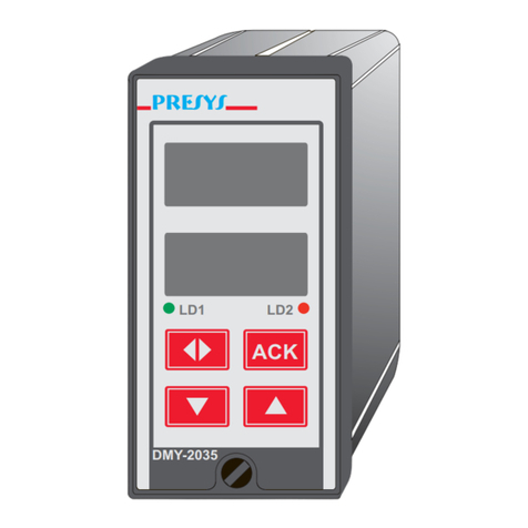
Presys DMY-2030-F User manual

Frequency Digital Indicator
DMY-2030-F / DMY-2030-F Light
EM0136-01
Technical Manual
Empresa Nacional
Tecnologia 100% Brasileira
R
PRESYS DMY-2030-F
LD1 LD2
PRESYS DMY-2030-F Light
LD1 LD2
presys

Declaration of Conformity
Presys Instruments
Presys unit DMY-2030-F and DMY-2030-F Light has been designed to comply with the
following European Standards:
EN 50081-1: 1992 Electromagnetic Compatibility - Generic emission standard.
EN 50081-2: 1994
EN 50082-1: 1992 Electromagnetic Compatibility - Generic immunity standard.
EN 50082-2: 1995 (Performance criterion B).
EN 61010-1: 1993 Safety Considerations
I have made all reasonable enquiries regarding the unit stated and their conformance
to the EU, Low Voltage and EMC Directives. To the best of my knowledge and belief
this unit conform to these directives.
This Declaration is controlled under an ISO 9001:2008 system certificated by TÜV
Rheinland, certificate number CE, SIQ - 558 - Revision 11.
Signature
Name R. W. Silva
Position Manager
presys

PRESYS ⏐Instruments DMY-2030-F / DMY-2030-F Light
EM0136-01
TABLE OF CONTENTS
1.0 - Introduction .........................................................................................................1
1.1 - Description.......................................................................................................1
1.2 - Order Code......................................................................................................2
1.3 - Technical Specifications..................................................................................3
2.0 - Installation...........................................................................................................5
2.1 - Mechanical Installation ....................................................................................5
2.2 - Electrical Installation........................................................................................5
2.3 - Process Input Signal Connections...................................................................6
2.4 - Output Connection...........................................................................................7
2.5 - Connection Diagram......................................................................................10
2.6 - Communication..............................................................................................11
2.7 - Engineering Units ..........................................................................................11
3.0 - Operation ..........................................................................................................12
3.1 - Normal Operation ..........................................................................................12
3.2 - Configuration.................................................................................................12
4.0 - Maintenance......................................................................................................25
4.1 - Indicator Hardware ........................................................................................25
4.2 - Hardware Configuration.................................................................................26
4.3 - Snubber Use for Relay ..................................................................................26
4.4 - Optional Module Connection .........................................................................27
4.5 - Calibration .....................................................................................................30
4.6 - Hardware Maintenance Instructions ..............................................................32
4.7 - List of Components........................................................................................33
4.8 - List of Recommended Spare Components....................................................36
presys

PRESYS ⏐Instruments DMY-2030-F / DMY-2030-F Light
Introduction
Page 1
1.0 - Introduction
1.1 - Description
PRESYS DMY-2030-F and DMY-2030-F Light Indicators are microcontroller-
based instruments which show process variables generated by frequency sensors such
as magnetic pickups, tachogenerators, inductive, capacitive or optical proximity switches,
intrinsic safety NAMUR type sensors (DIN-19234) etc.
They can communicate with computers by means of an optional communication
module RS-232 or RS-422/485.
DMY-2030-F Indicator is able to monitor two frequency inputs and
DMY-2030-F Light Indicator monitors one frequency input for signals of sinusoidal,
squared or triangular waveforms and all pulses with amplitude between 300mVp-p and
30Vp-p (Volt peak-to-peak) or input from contact closures. The input frequency ranges
from 0Hz to 30kHz. The indication on the display is user-configurable, which allows the
process variable to be shown in engineering units (rpm, Hz, etc.).
All configuration data can be protected by password and are stored in non-volatile
memory in case of an external power failure.
For each input there is a 24Vdc voltage source for frequency sensor excitation,
isolated from outputs and with protection against short-circuit.
According to modularity design concept, the Indicators accept up to four output
modules. The types of output are: retransmittion, SPDT relay, SPST relay and open
collector voltage. The outputs are isolated from the inputs.
They accept 90 to 240Vac or 130 to 340Vdc (with any polarity) power supply.
The instruments have extruded aluminum case which avoids electrical noise,
electromagnetic interference, radiofrequency interference, etc. and their robust
construction makes them tough enough for the most hostile environment.
PRESYS
DMY-2030-F
Light
LD1 LD2
PRESYS
DMY-2030-F
LD1 LD2
UpEnter Down
Place for sticking
the Engineering
Unit Label
Fig. 1 - DMY-2030-F and DMY-2030-F Light Indicators front panels
presys

PRESYS ⏐Instruments DMY-2030-F / DMY-2030-F Light
Introduction
Page 2
The front panel of the instruments has a high visibility display configurable up to
4 ½ digits which can show the process variable from channel 1, channel 2 or from both
channels in the scan mode for the DMY-2030-F Indicator, and only channel 1 for the
DMY-2030-F Light Indicator. During configuration, the display shows mnemonics and
parameter values. The couple of leds and the display can be used as alarm indications
or can be associated with outputs, relays, open collectors or triacs. Therefore, there are
up to seven alarm indications (four alarm modules, the display and two leds). The alarm
outputs can be configured, independently, to operate in the latch mode, demanding the
operator acknowledge by means of the front panel keys in order to deactivate the
outputs after the process variable returns to normal condition.
Up to two retransmitter outputs are available for the DMY-2030-F Indicator and
one retransmitter output for the DMY-2030-F Light Indicator to provide linear output
signal of 4 to 20 mA, 1 to 5 V or 0 to 10 V directly proportional to the process variable
measured. This signal allows the retransmittion of the variable to a distant location. In
case only one analogic output is used, it is possible to use up to three alarm outputs and
when using two analogic outputs, it is possible to use up to two alarm outputs.
1.2 - Order Code
DMY - 2030 - F / DMY - 2030 - F Light - ___ - ___ - ___ - ___ - ___ - ___ - ___
A B C D E F G
Field A Output 1
0 Not used
1 4 to 20mA
2 1 to 5V
3 0 to 10V
4 SPST relay
5 Open collector voltage
6 Solid state relay
Field B Output 2
0 Not used
1 4 to 20 mA (only for DMY-2030-F)
2 1 to 5 V (only for DMY-2030-F)
3 0 to 10 V (only for DMY-2030-F)
4 SPST relay
5 Open collector voltage
6 Solid state relay
Field C Output 3
0 Not used
1 SPDT relay
2 Open collector voltage
3 Solid state relay
Field D Output 4
Same code of output 3
presys

PRESYS ⏐Instruments DMY-2030-F / DMY-2030-F Light
Introduction
Page 3
Field E Power Supply
1 90 to 240 Vac or 130 to 340 Vdc (any polarity)
2 24 Vdc
3 12 Vdc
Field F Communication
0 Not used
1 RS-232
2 RS-485
3 RS-422
Field G Case Protection Grade
0 General usage, protected place
1 Front aspersion-proof
2 Weather-proof
Note 1 - The input ranges, indication, relay usage as alarms and the alarm points
are, among other things, items that the user can program through the front keys (if
wanted, specify this information so that all the configuration can be made by PRESYS).
Note 2 - Other hardware and software features are available under previous
consult.
Code Example:
1) DMY - 2030 - F - 0 - 0 - 1 - 1 - 1 - 0 - 0
This code defines a DMY-2030-F Indicator with two SPDT relays which can be
used as high and low alarms, 90 to 240 Vac or 130 to 340 Vdc electric power supply,
protected field usage.
1.3 - Technical Specifications
Inputs:
•Two frequency inputs (DMY-2030-F) or one frequency input
(DMY-2030-F Light) for connection of frequency signals of sinusoidal, or
triangular waveforms, pulses with amplitude between 300 mVp-p and
30 Vp-p and input form contact closures. 70 V maximum DC voltage. Input
impedance greater than 60 kΩ(sinusoidal, 1 kHz). Table 1 shows reading
accuracy and display resolution according to frequency range.
Frequency Range Accuracy Resolution
0.0000 Hz - 3.0000 Hz 0.0002 Hz 0.0001 Hz
0.000 Hz - 30.000 Hz 0.002 Hz 0.001 Hz
0.00 Hz - 300.00 Hz 0.02 Hz 0.01 Hz
0.0Hz - 3000.0Hz 0.2Hz 0.1Hz
0Hz - 30000Hz 2Hz 1Hz
Table 1 - Reading accuracy and resolution.
presys

PRESYS ⏐Instruments DMY-2030-F / DMY-2030-F Light
Introduction
Page 4
Outputs:
•Analog output 4 to 20 mAdc, 1 to 5 Vdc, 0 to 10 Vdc, use of optional
modules with plug-in fitting for up to two modules for DMY-2030-F and one
module for DMY-2030-F Light, 300 Vac galvanically isolated from inputs
and power supply.
•SPDT relays for alarm rated for 3A at 220 Vac, or up to 10A at 220 Vac
under order (in this case, the alarm module is not plugged to a connector,
but soldered to the board). It is possible to use up to 4 alarm modules
(using the connectors of the two analog outputs). That is, in case of using
one analog output, up to three alarm modules can be used, or when using
two analog outputs, up to two alarm modules can be used.
•Logic signal, open collector transistor, 24 Vdc, 40 mA max. with isolation.
•Solid state relay rated for 2A at 250 Vac with isolation.
Serial Communication:
RS-232 or RS-485, with 50 Vdc isolation, as an optional module for
connection in the CPU board.
Indication:
Standard indication of -9999 to 30000 range.
Configuration:
By front panel push-buttons and internal jumpers.
Scanning time:
71ms standard. The display is updated each 0.5 second.
Accuracy:
±0.5% of full scale for analog retransmitter output and 750Ωmaximum
load.
Stability at ambient temperature:
±0.005% per °C of span referred to 25°C ambient temperature.
Power Supply:
Universal 90 to 240Vac or 130 to 340Vdc (any polarity), 10W nominal;
24Vdc, 12Vdc and other values are optional.
Frequency sensors power supply:
24Vdc voltage and 50mA maximum, isolated from outputs, with
short-circuit protection.
Operating ambient:
0 to 50°C temperature and 90% maximum relative humidity.
Dimensions:
1/8 DIN (48 x 96mm) with 162mm depth, panel cut of 45 x 92mm.
Weight:
0.5kg approx.
Warranty:
One year.
presys

PRESYS ⏐Instruments DMY-2030-F / DMY-2030-F Light
Installation
Page 5
2.0 - Installation
2.1 - Mechanical Installation
DMY-2030-F and DMY-2030-F Light Indicators front panel has 1/8 DIN size
(48 x 96 mm).
They are fixed by the rails which press them against the back side of the panel.
After preparing a 45 x 92 mm cut in the panel, remove the rails from the Indicator
and slide its rear through the cut until its front reaches the panel. Place the rails again in
the Indicator from the back of the panel and tighten the screws as shown in Figure 2.
Fig. 2 - Dimensional drawing, panel cutout and side view
2.2 - Electrical Installation
DMY-2030-F and DMY-2030-F Light Indicators may be powered by voltage
between 90 and 240Vac or 130 to 340Vdc, with any polarity. Remember that the internal
circuit is powered whenever the instrument is connected to the external power supply.
presys

PRESYS ⏐Instruments DMY-2030-F / DMY-2030-F Light
Installation
Page 6
Input and output signals must be connected to the instrument only when it is
turned off.
Figure 3 shows the instrument rear terminals for connection of power supply,
ground, communication, process input and output signals.
Signal wiring must be kept far away from power wires.
Due to its metal case the instrument ground should be connected to earth ground.
Never connect the ground to neutral terminal.
NEUTRAL PHASE
24Vdc/
12Vdc
23 ( )
24 ( )
+
*
Fig. 3 - Indicator terminals
2.3 - Process Input Signal Connections
The Indicators accept the connection of pulses with amplitude between 300 mVp-p
and 30 Vp-p or contact closures to the frequency inputs.
The contact closure input is enabled by internal jumper (see section 4.2 on
Hardware Configuration).
In order to avoid noise in the wiring, use twisted pair cable and cross sensor
connection wire inside a metallic tube or use shielded cable. Make sure to connect only
one shield wire end either to board terminal or to sensor ground, as shown in the next
section.
WARNING: GROUNDING TWO SHIELD WIRE ENDS MAY CAUSE NOISE IN THE
INDICATOR.
presys

PRESYS ⏐Instruments DMY-2030-F / DMY-2030-F Light
Installation
Page 7
INPUT 2**
+24Vdc*(frequency sensor power supply)
+24Vdc*
(*) Other values may be available under consult
(**) Only for DMY-2030-F
INPUT 1
Fig. 4 - Input Connection Diagram
Frequency signals must be applied to terminals 2(+) and 3(-) for input 1 and to
terminals 5(+) and 6(-) for input 2 (only for DMY-2030-F).
Terminal 1 is a voltage source for the frequency sensor used in input 1, when it is
necessary to power the sensor. The voltage level is 24 Vdc referred to terminal 3.
Terminal 4 is the voltage source for the sensor in input 2, with 24Vdc referred to terminal
6. The voltage level may be changed under consult. Terminal 7 has no function in the
frequency instruments.
The inputs allow the connection of a 2-wire intrinsic safety NAMUR type sensor
directly to the terminals (+) and (-) without the need of an external resistor, which
requires the use of jumper JS1 for input 1 or JS2 for input 2 in the CPU Board. The
sensor power supply voltage level and the internal resistor value Rvcomply with DIN-
19234: 550-1100 W and 8.2V (7.7-9.0V).
Figure 5 shows the possible sensor connections to input 1. In order to connect a
sensor to input 2, use the terminals corresponding to those shown by the figure.
2.4 - Output Connection
In the most complete version, the Indicators can be provided with up to four
output signals: outputs 1 to 4. For DMY-2030-F, outputs 1 and 2 are used as
retransmitter or alarm outputs and outputs 3 and 4 are used only as alarm outputs, while
for DMY-2030-F Light output 2 is used only as alarm output.
In the case of outputs 1 (in both Indicators) and 2 (in DMY-2030-F) one can have
six different types of outputs: retransmitter (4 to 20mA, 0 to 5Vdc or 0 to 10Vdc), SPST
relay, open collector voltage and solid state relay.
For outputs 2 (in DMY-2030-F Light), 3 and 4 (in both Indicators), there are three
different types of outputs: SPDT relay, open collector voltage and solid-state relay.
Figure 6 shows the Indicator outputs.
presys

PRESYS ⏐Instruments DMY-2030-F / DMY-2030-F Light
Installation
Page 8
Note - For inductive proximity switches, connect the shield to the common
terminal of the instrument (terminal 3 for input 1 and terminal 6 for input 2).
Fig. 5 - Sensor connection
presys

PRESYS ⏐Instruments DMY-2030-F / DMY-2030-F Light
Installation
Page 9
Note that the output terminals will present the signals only if the
corresponding optional module is installed and the output is correctly configured.
For the analog outputs, refer to section 3.2 on Configuration and 4.4 on Optional
Module Connection for further details on installation and configuration of optional
modules.
(*) Position of relay contacts when SAFE option is enabled (see section 3.2 on Configuration), the Indicator is powered on
and in non-alarm condition. When the Indicator is powered off or in alarm condition with SAFE option disabled, the position
of the relays changes.
(**) Retransmitter output 2 only for DMY-2030-F.
Fig. 6 - Output Connection
presys

PRESYS ⏐Instruments DMY-2030-F / DMY-2030-F Light
Installation
Page 10
2.5 - Connection Diagram
presys

PRESYS ⏐Instruments DMY-2030-F / DMY-2030-F Light
Installation
Page 11
2.6 - Communication
DMY-2030-F and DMY-2030-F Light Indicators communicate with computers
through RS-232 or RS-422/485 when the optional communication module is installed
and the communication parameters are configured.
Specific information on communication and signal connection is described in the
communication manual.
2.7 - Engineering Units
A label with several Engineering Units is supplied with each Indicator. Select the
one corresponding to the variable shown on the display and stick it on the front panel of
the Indicator.
presys

PRESYS ⏐Instruments DMY-2030-F / DMY-2030-F Light
Operation
Page 12
3.0 - Operation
3.1 - Normal Operation
DMY-2030-F and DMY-2030-F Light Indicators have two modes of operation:
normal operation and configuration mode.
During normal operation, the Indicators monitor the inputs, verify alarm conditions
and activate the four outputs when necessary.
Configuration mode is used to select and configure all the Indicator parameters.
The normal operation mode, in which the Indicator is to be found most of the time,
is called level zero. In this level, the three front panel keys have the following functions:
ENTER
Key
It changes from level zero to level 1 or asks the password,
depending on the configuration.
DOWN
Key
It changes the channel shown on the display. If the
display shows channel 1 (2), after pressing DOWN, the
display will show the measured variable from channel 2
(1).
UP
Key
It shows the outputs configured as alarms which need
acknowledgment to turn to normal state. (*)
(*) In order to view the monitored variable, continue to press the UP key. In case
there are no activated relays with LATCHED function enabled, the No.Ack. message will
be shown.
3.2 - Configuration
In order to access configuration mode the operator is required to provide a
password which avoids a non-authorized person to change any critical parameters of the
process.
So, when ENTER is pressed within the normal operation mode, one of the
following events can happen, depending on the current configuration:
i) To access directly level 1 (GENERAL) of configuration mode, which indicates the
instrument was not configured with a password system.
ii) To display the PASS warning, indicating that the instrument is provided with a
password system (a key sequence or a value), according to Figure 7.
presys

PRESYS ⏐Instruments DMY-2030-F / DMY-2030-F Light
Operation
Page 13
Fig. 7 - Password through key sequence or value
In case of a key sequence password, the user should press the UP, DOWN and
ENTER keys (exactly in this order) to access the configuration levels.
For a value password, the user must press the ENTER key for a second time in
order to view the number 00000 with the right end digit blinking. The position which is
blinking indicates the digit in the number to be changed by the user with the UP and
DOWN keys. Move to the digits on the left by pressing ENTER. After entering all digits,
press ENTER again. If the password is correct level 1 is accessed; otherwise, it returns
to normal operation (see Figure 7).
The user can choose also both password systems, key and value. In this case, if
the user provides an incorrect sequence of keys, the display goes immediately to the
value password system.
The password number may be chosen by the user (personal) or it could be used
the number 2030. Note that the number 2030 is always accepted by the value password
system, which helps the user in case he forgets his password. In order to enter a number
for password or for any other parameter use the Indicator front panel keys with the
following functions:
UP key Increases values being set
DOWN key Decreases values being set
ENTER key Changes position to the left digit
All configuration parameters are stored in the non-volatile memory and determine
the normal operation of the instrument. With these parameters the user can adjust the
instrument to his needs, when it is necessary to change the configuration from factory.
Configuration parameters are distributed in six hierarchical levels shown in
Figure 8.
In order to move through the levels and access the parameters of any one of
them, use the front panel key which have the following functions:
presys

PRESYS ⏐Instruments DMY-2030-F / DMY-2030-F Light
Operation
Page 14
ENTER key Moves into the indicated level
UP key Moves to higher levels
DOWN key Moves to lower levels
Warning: In the diagrams below, the rectangles represent the display appearance
after selection of the ENTER, UP and DOWN keys.
Fig. 8 - Parameter levels diagram
The hierarchical levels are presented in sequence. The options of each level are
explained step by step with all their corresponding parameters.
Inside each level, the front panel keys have the following functions:
UP key Moves the options in increasing direction
DOWN key Moves the options in decreasing direction
ENTER key Confirm or advance options inside a
level, if the display does not show ESC.
When ESC is shown, it goes back
one or more positions.
Level 1 - GENERAL
Level 1 presents the options: TAG, SOFT, PASS and INDIC (see Figure 9).
TAG - consists in an alphanumeric identification for the instrument. The procedure
to enter the tag or any other parameter is the same as described previously for the
password (refer to value password for the functions of the ENTER, UP and DOWN
keys).
presys

PRESYS ⏐Instruments DMY-2030-F / DMY-2030-F Light
Operation
Page 15
SOFT - shows software version.
PASS - allows the user to enable or disable the password system for accessing
the configuration mode. The password system may be chosen as key sequence, a value
(number chosen by the user and number 2030) or both. The correct key sequence is
obtained by pressing the UP, DOWN and ENTER keys in this order.
INDIC - is an option for the visualization of the measured variables on the display.
It allows the user to view the values of channels 1 and 2 only by pressing the UP and
DOWN keys, or it sets the instrument to change automatically the indication of the
measured variable of each channel. In the former case choose NO for TWO option, and
for the latter case, choose YES (automatic scan mode) for TWO option and provide the
exhibition times (given in seconds) for viewing each channel.
Fig. 9 - GENERAL level options
The table below refers to the ranges of the parameters shown in Figure 9.
Mnemonic Parameter Range Factory
Value Units
TAG instrument
identification
_____________
F2030
__________
SOFT software version
_____________ 1.20
__________
VALUE user password -9999 to 30000 0 __________
TIME1 channel 1
exhibition time
1 to 3000
5
seconds
TIME2 channel 2
exhibition time
1 to 3000
1
seconds
presys

PRESYS ⏐Instruments DMY-2030-F / DMY-2030-F Light
Operation
Page 16
Level 2 - INPUT
Level 2 - Input allows the selection of the operation range of each input (given in
Hz) and the association of 2 indication values, in engineering units, to the limits of the
selected range. It is also possible to disable any input.
(1) IT FOLLOWS THE SAME OPTIONS OF CH-2
(2) ONLY FOR DMY-2030-F
Fig. 10 - INPUT level options
The table below refers to the ranges of the parameters shown in Figure 10.
Mnemonic Parameter Range Factory
Value Units
LIM LOW input signal associated
with Eng Low
0 to 30000
0
Hz
LIM HIGH input signal associated
with Eng High
0 to 30000
1000
Hz
ENG LOW display indication
associated with
Lim Low
-9999 to 30000
0
EU*
ENG HIGH display indication
associated with
Lim High
-9999 to 30000
1000
EU
OFF SET constant added to
display indication
-9999 to 30000
0
EU
FILTER time constant of 1st
order digital filter
0.0 to 25.0
0.0
seconds
(*) EU - Engineering Unit
presys

PRESYS ⏐Instruments DMY-2030-F / DMY-2030-F Light
Operation
Page 17
The operation range of each input must be configured (in Hz) through Lim Low
and Lim High parameters in SCALE option. Lim Low is configured with the minimum
input frequency (in Hz, without decimal point) and Lim High is (generally) the maximum
frequency of the range.
The indication on the display is configured by defining 2 points: P1 (Lim Low and
Eng Low) and P2 (Lim High and Eng High). The value configured for Eng Low will be
indicated on the display when the frequency input signal corresponds to the minimum
frequency of the operation range configured (Lim Low). In the same way, Eng High will
be generally the indication of the maximum frequency of the range (Lim High).
Observe the boundaries of the parameters Eng High and Eng Low and also the
resolution of the instrument when defining the decimal point position. The line defined by
P1 and P2 is not confined in the interval P1-P2, see Figure 11.
(*) BOUNDARIES OF ENG HIGH AND ENG LOW PARAMETERS.
Fig. 11 - Input Configuration
DC.PT places the decimal point on the display for readout in Engineering Unit
(EU) of each channel.
OFSET (as shown on the display) - allows the user to enter an off-set value in
Engineering Units to be added to the measured variable.
FILTER - this parameter provides the time constant of a first order digital filter
associated to the selected input. In order to leave the signal without filter set this
parameter to zero.
presys
This manual suits for next models
1
Table of contents
Other Presys Measuring Instrument manuals

Presys
Presys DMY-2030-CC User manual

Presys
Presys DMY-2030 Light User manual

Presys
Presys TE-25N User manual
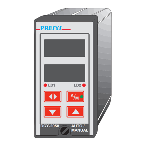
Presys
Presys DCY-2058 User manual
Presys
Presys DMY-2015 User manual

Presys
Presys DMY-2030-TOT Light User manual
Presys
Presys TA-25NL User manual
Presys
Presys DMY-2030 Light User manual
Presys
Presys DMY-2030 Light User manual

Presys
Presys PROFI BUS DMY-2015-PB User manual
