PREVOST PPS Guide

MANUEL TECHNIQUE
CONCEPT ALUMINIUM PPS POUR
RÉSEAUX AIR COMPRIMÉ
SOMMAIRE
Description du produit ……………… 2
Calcul du diamètre du tube ………… 3
Méthode d'installation ……………… 4
Règles générales de mise en œuvre
et de précautions de montage ……… 5
TECHNICAL DOCUMENTATION
SYSTEM PPS FOR COMPRESSED
AIR NETWORK
CONTENTS
Product description ………………… 8
Calculating pipe diameter…………… 9
Installation method …………………10
Assembly:
general rules and precautions ………11
TECHNISCHE DOCUMENTATION
PPS-SYSTEM – ALUMINIUM
– KOMPONENTEN FÜR
DRUCKLUFTLEITUNGEN
INHALVERZEICHNIS
Produktbeschreibung ………………14
Berechnung des Rohrdurchmessers …15
Installationsverfahren ………………16
Allgemeine regeln und
Vorsichtsmassnahmen
bei der Montage ……………………17
DOCUMENTACIÓN TECNICA
CONCEPTO PPS PARA REDES DE
AIRE COMPRIMIDO
SUMARIO
Descripción del producto ……………20
Cálculo del diámetro del tubo ………21
Método de instalación ………………22
Normas generales de instalación y
precauciones de montaje……………23
DOCUMENTAZIONE TECNICA -
DEL SISTEMA PPS PER RETI
D'ARIA COMPRESSA
SOMMARIO
Descrizione del prodotto ……………26
Calcolo del diametro del tubo ………27
Metodo d'installazione………………28
Regole generali di implementazione e
precauzioni di montaggio ……………30
PPS
PPS MT17- 02.18

2 3
DESCRIPTION DU PRODUIT
CONSIDÉRATIONS GÉNÉRALES
La nécessité de développements, d’expansions et de changements constants
des modes de production dans les établissements ainsi que l’évolution
de la technologie de production en forte tendance vers l’automatisation
exigent des systèmes de distribution d’air comprimé de taille importante
et facilement modiables.
Le système PPS a été conçu et réalisé pour la création de systèmes de
distribution d’air comprimé.
Les matériaux et le type d’assemblage ont permis la réalisation d’un système
exible, évolutif et compatible avec tous les systèmes PREVOST, capable
de résoudre tous les problèmes des équipements les plus complexes.
Le système de montage est simple et rapide et ne requiert pas l’utilisation
d’outillage coûteux et complexe. L’installation assure une parfaite étanchéité
pneumatique, une résistance mécanique remarquable et une efcacité
durable.
LA CORROSION
L’alliage d’aluminium employé pour le tube, l’électropeinture grâce à un
système de vernissage électrique à chaud ainsi que le traitement utilisé
pour les raccords offrent une tuyauterie qui ne présente aucun problème
de corrosion ou de dégradation des surfaces internes et externes, ce qui
permet d’obtenir une durée de vie du produit très importante, dans des
conditions d’utilisation normales.
LE COMPORTEMENT EN CAS DE CHOC
Les matériaux du système garantissent d’excellentes prestations quant
à la résistance mécanique, à la pression interne et aux chocs externes.
La tuyauterie est en mesure de supporter les chocs même violents, sans
aucun danger.
Les canalisations principales apparentes qui transportent de l’air comprimé
doivent être installées au moins à 2,5 mètres du sol et, par conséquent, ne
sont pas susceptibles de subir des chocs.
LES RAYONS ULTRAVIOLETS
L’aluminium est insensible à l’exposition aux rayons ultraviolets, ce qui
permet une installation à l’intérieur comme à l’extérieur.
LA RÉSISTANCE AU FEU
L’aluminium n’alimente pas et ne propage pas les ammes, offrant ainsi
une résistance au feu optimale.
Le système PPS est certié B – s1, d0 suivant la norme EN 13501-1 :
Classement au feu des produits et éléments de construction.
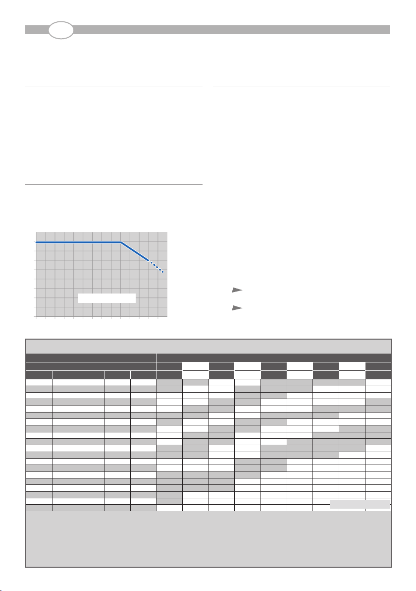
SOURCES DE CHALEUR
Le système en aluminium offre une grande résistance et supporte des
températures allant jusqu’à 80° C.
Voir la courbe de pression en fonction de la température page 3.
LE DÉBIT
Les débits du système PPS sont excellents, grâce à un faible coefcient de
frottement, à une grande section interne des tubes et à l’absence d’obstacles
ou de réductions de passage.
L’INSTALLATION
L’installation est rapide et simple, ce qui réduit au minimum les délais de
mise en service du système.
LES CARACTÉRISTIQUES EN TERMES DE
DIMENSIONS ET DE NORMES
Tous les produits sont garantis pour une utilisation conforme à celle indiquée
et uniquement dans les limites prévues par la présente documentation
technique et répondent aux Critères Essentiels de Sécurité conformément
aux dispositions de la directive DESP 2014/68/UE.
Le fabricant, PREVOST, dégage toute responsabilité si les installations et
les systèmes réalisés avec le système PPS ne sont pas utilisés et montés
selon les spécications et les limites indiquées dans le présent document.
Durant l’installation et à la n de celle-ci, il est nécessaire d’effectuer
certaines vérications ainsi qu’à la mise en service.
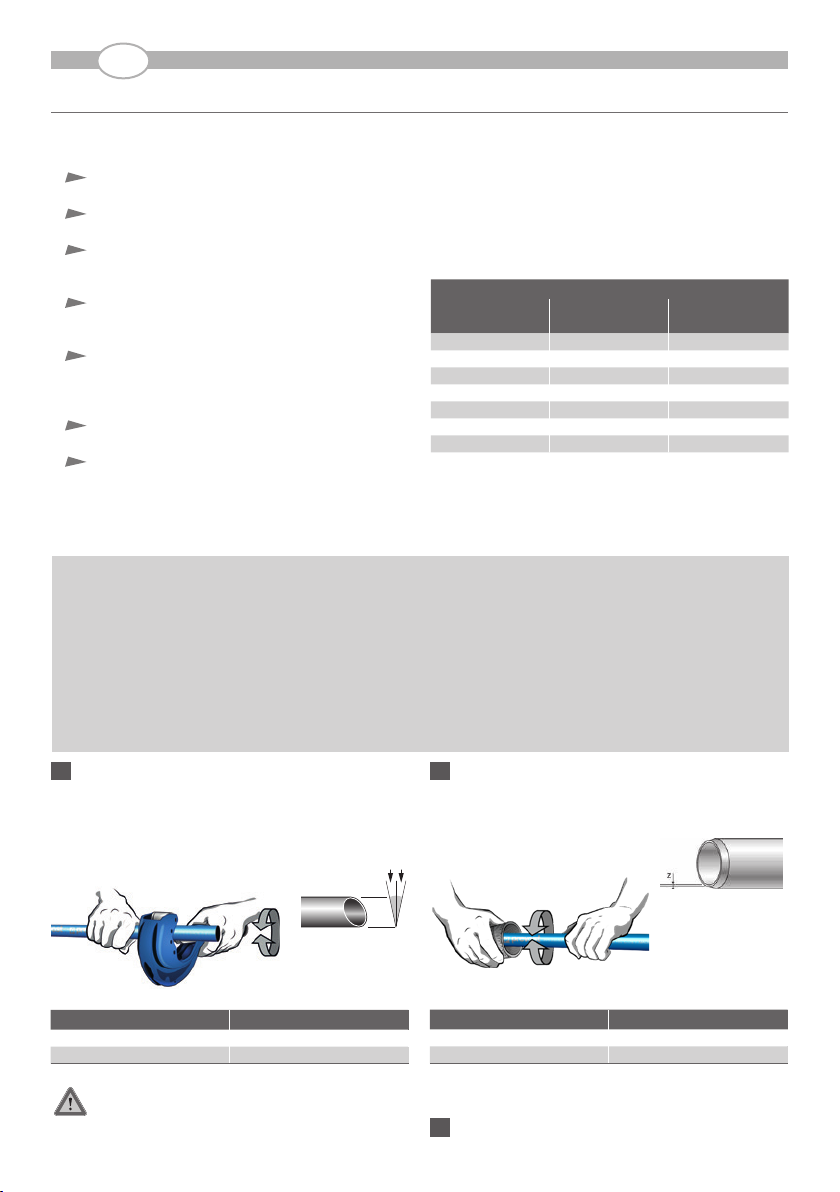
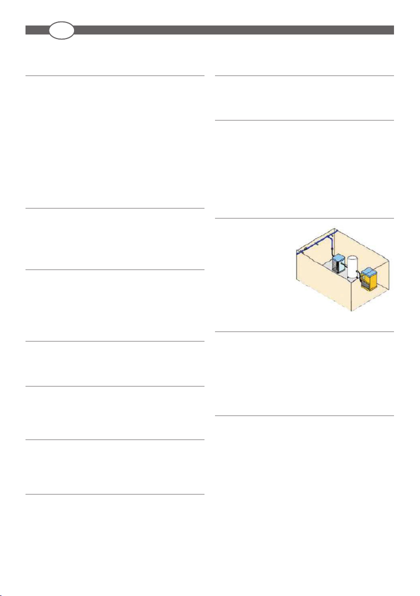
VIBRATIONS
Les compresseurs produisent
des vibrations qui peuvent être
nocives pour le système.
Il est conseillé de ne jamais
relier directement les tubes
rigides PPS au compresseur,
mais d’utiliser des tuyaux de
raccordement exibles.
COLORATION
Les couleurs disponibles correspondent à différentes application :
- Bleu = Air comprimé
- Gris = Vide
- Vert = Azote
Le système PPS est peint par électro-peinture, ce qui assure non seulement
la coloration mais également une protection optimale contre la corrosion.
COMPATIBILITÉ AVEC LES HUILES POUR
COMPRESSEURS
L’aluminium, qui constitue le système PPS, ne présente pas de problèmes
particuliers au contact d’huiles lubriantes pour compresseurs.
F

2 3
F
CALCUL DU DIAMÈTRE DU TUBE
CHAMPS D’APPLICATION
Le système PPS a été conçu pour le transport d’air comprimé à une pression
allant jusqu’à 16 bar à 20°C.
La gamme de produits disponibles permet la réalisation de systèmes
complets, de l’unité de production et de traitement jusqu’aux points
d’utilisation.
Le système PPS s’intègre parfaitement à toutes les gammes de produits
PREVOST.
COURBE DE PRESSION EN FONCTION DE LA
TEMPÉRATURE
Les composants du système PPS peuvent être utilisés à une pression
constante de 16 bar.
Toute augmentation de la température ambiante entraîne une baisse de la
pression de service suivant la courbe ci-dessous.
DIMENSIONNEMENT
Le réseau principal doit être de préférence bouclé.
La canalisation principale doit être xée avec une pente de 1 % an d’évacuer
les condensats vers les points bas (purges). La canalisation principale doit
être en mesure de véhiculer la totalité du débit du compresseur.
La canalisation principale doit être sufsamment dimensionnée pour
répondre au débit maximum requis à la pression de service donnée, pour
éviter les pertes de charges qui représentent un gaspillage d’énergie.
La quantité maximale d’air requis pour chaque descente est basée sur la
consommation maximale.
Chaque descente, multipliée par un facteur (compris entre 0,1 et 1)
représentant la fréquence d’utilisation de l’équipement connecté, fournira
une consommation moyenne.
La somme des consommations moyennes de toutes les descentes donnera
le débit maximum requis pour la canalisation principale.
Par précaution et pour répondre aux extensions futures, un pourcentage
supplémentaire sera ajouté à cette valeur.
Après l’obtention des débits maximums de chaque descente et de la
canalisation principale, le calcul du diamètre de chaque tube peut être
effectué facilement à l’aide du tableau ci-dessous.
Le calcul du diamètre du tube s'effectue en tenant compte:
du débit souhaité (perte de charge maxi de 5% par rapport à
la pression d'entrée).
de la longueur de canalisation principale.
Si la canalisation est bouclée, la longueur à prendre en compte est la
distance maxi entre la source d’air comprimé et le besoin.
Les pertes de charges sont causées par plusieurs facteurs :
- État de surface
- Changements de direction et courbes
- Obstacles (vannes, etc.)
- Changements soudains ou progressifs des diamètres
COMPRESSEUR* LONGUEUR DE LA CANALISATION PRINCIPALE
PUISSANCE DÉBIT 50 m 100 m 150 m 300 m 500 m 750 m 1000 m 1300 m 1600 m
kW CV Nm3/h Nl/min Scfm 164 ft 328 ft 492 ft 984 ft 1640 ft 2460 ft 3280 ft 4265 ft 5249 ft
2,2 3 22 367 13 16 16 20 20 25 25 25 25 32
3 4 30 500 18 16 20 20 25 25 25 32 32 32
4 5 40 668 24 20 20 20 25 25 32 32 32 32
5,5 7,5 50 833 29 20 20 25 25 32 32 32 32 40
7,5 10 70 1167 41 20 25 25 32 32 32 40 40 40
11 15 100 1667 59 25 25 32 32 40 40 40 50 50
15 20 150 2500 88 25 32 32 40 40 50 50 50 50
18 25 180 3000 106 32 32 40 40 50 50 50 63 63
22 30 220 3674 130 32 40 40 50 50 50 63 63 63
26 35 260 4167 147 32 40 40 50 50 63 63 63 63
30 40 350 5833 206 40 40 50 50 63 63 63 63 80
37 50 370 6179 218 40 40 50 50 63 63 63 80 80
45 60 500 8350 294 50 50 50 63 63 80 80 80 80
55 75 550 9185 324 50 50 50 63 63 80 80 80 80
75 100 750 12500 441 63 63 63 63 80 80 80
90 125 1000 16667 589 63 63 63 80 80
110 150 1100 18370 649 63 63 63 80 80
132 175 1500 25000 883 63 80 80 80
160 215 1750 29167 1030 63 80 80
200 270 2000 33333 1177 80 80 80
Le tableau ci-dessous permet de dénir le diamètre du tube* en fonction de la longueur du réseau et du débit** à distribuer.
* en mm, ** sous 6 bar
-10 0 10 20 30 40 50 60 70 80 90 100 110 120 °C
PN
16
14
12
10
8
6
4
2
0
Ø 16 mm -> Ø 80 mm

4 5
F
MÉTHODE D’INSTALLATION
DILATATION - CONTRACTION
Tous les matériaux subissent des variations de dimensions avec les
changements de température. En général, les matières plastiques subissent
des variations plus perceptibles que les métaux.
Par rapport à une température de référence (la température de pose) :
- elles se dilatent lorsque la température augmente,
- elles se contractent lorsque la température diminue.
La mesure de ces variations est donnée par le coefcient d de dilatation
linéaire.
Pour le système avec tube d’aluminium PPS, ce coefcient (d) est
de 0,024 mm/m/° C, soit 0,024 millimètres par mètre par degré Celsius.
Nous vous proposons, ci-dessous, une comparaison entre les coefcients
de dilatation linéaire de certains matériaux utilisés fréquemment :
La conception et l’exécution de tout type de système devront tenir compte
de ce phénomène, qui se calcule à l’aide de la formule suivante :
ΔL =d xL xΔT
TubeOù :
d= coefcient de dilatation linéaire
L = longueur du tube
ΔT = différence de température en degrés Celsius
DL = différence de longueur (dilatation ou contraction)
Exemple :
température de pose + 10° C ; longueur du tube 20 m ; température de
service 35° C
ΔT = 35 – 10 = 25° C
DL = 0,024 x 20 x 25 = 12 mm
Les principales conséquences des dilatations et des contractions sont :
Dilatation
Déformation des tubes compris entre deux points xes.
Compression des ouvrages, attaches ou appareillages qui
constituent des points xes, avec risque de déformation,
affaissement ou rupture.
Contraction
Traction des tubes compris entre deux points xes.
Compression des ouvrages, attaches ou appareillages qui
constituent des points xes, avec risque de déformation ou
de rupture.
Pour éviter que les effets de la dilatation et de la contraction ne causent des
dommages importants au système et altèrent son aspect, il faut suivre les
indications suivantes an de maintenir librement les tubes et de compenser
les dilatations et les contractions :
- Soutenir et renforcer le système de manière à ce que la
tuyauterie puisse coulisser librement entre deux points xes.
- Si deux points xes sont séparés par une distance induisant
une contraction ou une dilatation importante, il faut insérer un
compensateur entre ces deux points.
Acier 12,8 x 10
-6
m / m / °C
Cuivre 16,5 x 10
-6
m / m / °C
PPS 24 x 10
-6
m / m / °C
ABS 101 x 10
-6
m / m / °C
PVDF 120 x 10
-6
m / m / °C
PP 150 x 10
-6
m / m / °C
PE 200 x 10
-6
m / m / °C
Parmi les systèmes de compensation les plus efcaces,
nous vous suggérons la " Lyre " (ou OMEGA) et le " Changement de direction ".

4 5
F
MÉTHODE D’ANCRAGE
Le choix des supports et des renforcements destinés aux tubes doit être
fait avec une attention particulière. Ces éléments doivent, en effet, posséder
certaines caractéristiques :
Les supports doivent ancrer les tubes solidement à la structure de
la pièce.
Ils ne doivent pas rayer ni endommager les tubes, de quelque
manière que ce soit.
Ils doivent laisser sufsamment d’espace entre la tuyauterie et le mur
ou les autres obstacles, de manière à permettre des interventions
de maintenance ou autres.
Ils doivent maintenir les tubes parfaitement droits, de même que
soutenir la charge de tous les accessoires et d’une tuyauterie pleine,
en bloquant celle-ci dans les ancrages.
Un soin particulier doit être apporté au renforcement des accessoires
et des vannes. Ceux-ci étant sollicités durant les manoeuvres, leur
xation doit être indépendante de celle des tubes et permettre
l’activation de même que le démontage de ces derniers.
Prêter une attention particulière lors de la xation des extrémités
des tubes (bouchons, xations murales, descentes).
Le supportage des éléments additionnels (ltres, séparateurs,
vannes...) du réseau ne doit pas être assuré par le tube aluminium.
Des équerres de xation sont prévus à cet effet.
L’espacement entre les supports doit être établi selon des tableaux standard,
réalisés en fonction du diamètre, de la température et du poids du uide
transporté.
Les supports coulissants ne doivent pas entrer en contact avec des unions
ou autres accessoires an d’éviter tout blocage des mouvements du tube.
Lorsque des tubes sont installés horizontalement ou verticalement à moins
de 2,50 m du sol, il est indispensable de doubler le nombre de supports an
de s’assurer que les tubes sont solidement xés à la structure.
RÈGLES GÉNÉRALES DE MISE EN ŒUVRE ET DE PRÉCAUTIONS DE MONTAGE
ATTENTION: Respecter scrupuleusement les prescriptions annoncées pour l’étude du réseau.
Une installation mal conçue peut être dangereuse. Les précautions suivantes doivent être respectées:
•
Il est impératif que l’installation des réseaux soit réalisée par un professionnel formé.
• Les tubes doivent être alignés. En effet, les réseaux doivent être les plus rectilignes possibles an d’éviter les pertes de charges et le foisonnement des forces opposées
(les reliefs compliqués avec un grand nombre de coudes, de tés, etc. sont à proscrire)
• Pour toute longueur droite supérieure à 50 mètres, il est impératif de positionner des exibles de dilatation (ou de liaison) à raccords tournants qui :
- facilitent le montage réseau (gain de temps d’installation important)
- sécurisent les systèmes grâce à l’absorption et canalisation des forces (dilatation, rétractation)
• Les colliers PPS1 CI doivent être positionnés selon le tableau ci-dessus
• Les coupes doivent être effectuées de façon à ce qu’il n’y ait aucune contrainte sur les composants.
1
COUPER LE TUBE
La coupe doit être perpendiculaire à l’axe du tube et droite, avec une
tolérance de coupe de maximum 7° par rapport au plan théorique idéal
de 90°.
Utilisation d’un coupe tube " PPS CTU ".
Attention: Vérier le parfait état de surface des extrémités du
tube : éviter toutes rayures, chocs ou ovalisation du
tube pour en garantir une parfaite étanchéité.
2
CHANFREINAGE - ÉBAVURAGE
Après la coupe, ébavurer le tube à l'intérieur et exécuter impérativement
un chanfrein à l'extérieur (Z = 1/2 épaisseur du tube).
Effectuer ces opérations avec les outils à chanfreiner:
S’assurer de la bonne qualité du chanfrein et de l’absence de
copeau à l'intérieur.
3
NETTOYAGE TUBE ET RACCORD
≤ 7°
Diamètre (mm) Outils pour chanfreiner
16 à 50 PPS CH50
63 à 80 PPS CH110
Diamètre (mm) Coupe-tubes
16 à 50 PPS CTU63
63 à 80 PPS CTU110
ESPACEMENT ENTRE LES SUPPORTS
Diamètre Colliers de xation Espacement des colliers à
30 °C [m]
16 PPS1 CI16 3
20 PPS1 CI20 3
32 PPS1 CI32 3
40 PPS1 CI40 4
50 PPS1 CI50 4
63 PPS1 CI63 4
80 PPS1 CI80 4

6 7
F
Il est important de contrôler l’état de surface des zones d’étanchéité et
d’éliminer les résidus, les poussières et les copeaux restés à l’intérieur du
tube suite à la coupe, an d’éviter d’éventuels problèmes liés aux
équipements pneumatiques.
Il est fortement recommandé de procéder à une opération de nettoyage à
l’aide d’un chiffon propre et d’un produit dégraissant non agressif pour les
surfaces, et plus particulièrement pour les extrémités de tubes et l’intérieur
des raccords. La graisse et les lubriants nuisent à la qualité des produits
dans leur utilisation, il est donc conseillé d’utiliser une eau savonneuse
(Réf : PPS AL).
Faire attention aux chocs et aux rayures.
4
ASSEMBLAGE RACCORD SUR TUBE
1_Desserrer l’écrou d’un tour minimum (veiller à ne pas le démonter).
2_Vérier la propreté de l’intérieur du raccord (joint et griffes).
3_Contrôler la présence et le bon positionnement de l’ensemble des
composants à l’intérieur du raccord.Vérier l’orientation des dents
de maintien (griffes) comme sur le schéma ci-dessous.
4_Pré serrer l’écrou extérieur à la main, de manière à compenser
l’éventuel jeu existant entre les composants (avant d’insérer le tube).
5_ A l’aide d’un feutre, tracer un repère sur le tube an de déterminer
la longueur de pénétration dans le raccord en fonction du
tableau. L’utilisation du repère sur le raccord ou la clé de serrage
PPS1 CLE permet de déterminer plus facilement la longueur
d’emmanchement.
Cette longueur de pénétration comprend le serrage de l’écrou.
• Vérier la longueur d’emboîtement depuis l’épaulement butée à l’intérieur
du raccord jusqu’au sommet de l’écrou
• Reporter la longueur d’emboîtement sur le tube à chaque nouvelle
connexion à réaliser
• Lubrier l'extrémité du tube et l'intérieur du raccord à l'aide du liquide
d'assemblage (PPS AL)
6_Emboîter le tube dans l'axe du raccord en exerçant une légère
rotation pour atteindre le fond de la butée du raccord.
Diamètre (mm) Longueur (mm)
16 32
20 38
25 44
32 52
40 62
50 72
63 83
80 95
Attention:
Il est strictement interdit d’utiliser des lubriants, huiles ou corps gras
dont la compatibilité chimique n’est pas assuré. Il est conseillé d’utiliser
une eau savonneuse. En effet, la présence ou l’utilisation d’un corps
gras quel qu’il soit engendre une incertitude et minore les capacités de
connexion du tube et des raccords.
Dans le doute veuillez nous consulter!
(Réf : PPS1 CLE)

6 7
F
5
SERRAGE DE L’ÉCROU DU RACCORD
Serrer l'écrou manuellement jusqu'au blocage puis compléter l'opération
à l'aide de la clé (Réf. PPS1 CLE) en réalisant 1/4 de tour.
Après le vissage, s’assurer que le repère ne soit plus visible.
Une clé dynamométrique peut être utilisée dans le carré présent sur la clé
de serrage PPS1 CLE.Après la mise en pression, vérier que le repère soit
aligné et que les écrous ne sont pas desserrés.
Contrôle nal bon/mauvais
6
POUR LE DÉMONTAGE
Le concept PPS permet un démontage instantané.
Dévisser l’écrou entièrement du raccord pour ôter le tube an de ne pas
l’endommager.
Attention: Avant de remonter l’écrou, il est indispensable
de contrôler l’état du tube et de changer les kits
de pièces internes.
Se reporter au paragraphe 2 si nécessaire.
7
ÉTANCHÉITÉ DES FILETAGES
Il est conseillé d’employer du téon
®
(réf : TEFLON 12), du l téonné, de
la lasse ou de la pâte à joint de plomberie pour le montage des letages
et des taraudages.
Serrer modérément à la clé an de ne pas endommager le raccord.
8
PHÉNOMÈNES DE DILATATION DUS AUX
CHANGEMENTS DE TEMPÉRATURE
Il est impératif d’installer un système de compensation, calculé lors
de la conception sur plan, pour palier au phénomène de dilatation.
Le non respect des règles de conception du réseau entraîne la
responsabilité du client.
PREVOST est à votre disposition pour créer ou valider vos plans.
9
NETTOYAGE DU RÉSEAU
Avant de monter les raccords et les accessoires sur le réseau, procéder au
soufage de l’installation pour évacuer les copeaux
10
VÉRIFICATION AVANT MISE EN PRESSION
Les assemblages effectués avec le système «PPS» ne requièrent pas de
temps d’attente après leur exécution: la mise sous pression est immédiate.
1_Une fois l’assemblage terminé, il convient de vérier qu’il n’y ait pas d’anomalies,
de coups, d’entailles ou d’abrasions et de vérier que l’ensemble des raccords
soit bien connecté sur le tube, le repère qui a été réalisé lors du montage ne doit
plus être visible.
En cas d’anomalies, il faut remplacer immédiatement les parties défectueuses
ou déformées du réseau.
2_Vérier l’ensemble des points d’ancrage des colliers ou consoles murales.
3_La mise en pression du réseau doit se faire en 2 temps:
• Avant d’atteindre la pression d’essai prévue, il faut faire un test préalable
en montant en pression progressivement jusqu’à un maximum de 3 bar, de
manière à identier à l’avance les éventuelles fuites et/ou les éventuelles
jonctions effectuées de manière incomplète ou imparfaite.
Une fois les vérications et les éventuelles mises au point exécutées,maintenir
la pression à 3 bar et attendre au moins 5 minutes avant de procéder à une
autre augmentation.
• Pour la mise en pression, il est suggéré de procéder graduellement et de façon
constante à l’augmentation de pression (1 bar toutes les 4 à 6 secondes)
jusqu’à ce que la moitié de la valeur d’essai soit atteinte.
La pression d’essai atteinte, celle-ci doit être constante (sans chute signicative) pendant
au moins 10 minutes.
Après les premières 48 à 96 heures, vérier toutes les connexions et s’assurer que tous
les écrous sont bien serrés, car ils peuvent être desserrés suite à la mise en place des
composants. Le repère tracé lors du serrage des écrous (Paragraphe 5) doit être aligné.
CONSTAT D’INCIDENTS
En cas de problèmes constatés, le client ou l’installateur devra collecter les
informations suivantes pour faire une déclaration de sinistre :
- la pression de service
- la température dans le local
- le métrage développé et les différentes sections utilisées
- le descriptif de l’incident :A quel moment? En quel lieu de l’installation ?...
- des photos de l’installation
Diamètre
(mm) Couple de
serrage (Nm)
16 8
20 15
25 21
32 32
40 32
50 55
63 65
80 70

8 9
GB
PRODUCT DESCRIPTION
BACKGROUND
Today’s companies are faced with the necessity to constantly develop,
expand and modify production methods. Coupled with increasingly
automated production technologies, this necessity makes large-scale,
easy-to-modify compressed air distribution systems a must.
System PPS is specially designed for building compressed air distribution
systems.
Its materials and assembly methods make it a exible and scalable solution
that is compatible with all PREVOST systems and able to meet even the
most complex equipment problems.
Installation is quick, easy and requires no costly or complicated tools.
Once installed, the completed ringmain ensures a good seal, outstanding
mechanical strength and lasting efciency.
CORROSION
The aluminium alloy pipes, baked e-coating nish and render System PPS
pipes and ttings completely resistant to internal and external corrosion and
damage and signicantly extend their service life under normal conditions
of use.
IMPACT RESISTANCE
System PPS pipes and ttings are constructed of materials which offer
excellent resistance to internal pressure and external impacts, even violent
ones.
Exposed main pipes conveying compressed air must be installed at least 2.5
metres above the oor to protect them from any risk of impacts.
UV RAYS
Aluminium is not affected by UV rays, allowing it to be used inside as
well as outside.
FIRE RESISTANCE
Aluminium has excellent re resistance properties. It does not burn or
spread ames. PPS system is certied B – s1, d0 according to standard
EN 13501-1 : Fire test to Building Material
SOURCES OF HEAT
The extremely tough aluminium system withstands temperatures of up
to 80°C.
See the effect of temperature on pressure on page 9.
FLOW RATE
Because of their low friction coefcient, wide inner sections and the absence
of obstacles or narrow passages, PPS ttings offer excellent ow rates.
INSTALLATION
Quick and easy to install, System PPS ringmains are ready to operate in
less time.
SIZES AND STANDARDS
Every component is guaranteed when used as indicated and solely within the
limits of this technical documentation and meets Essential Safety Criteria in
accordance with the provisions in pressure equipment directive 2014/68/UE.
The manufacturer, PREVOST, shall not be held responsible if any ringmain
or system built with System PPS components is not used or assembled
according to the specications and limits indicated in this document.
A number of checks are required when installing and commissioning a
ringmain.
VIBRATIONS
Compressors generate
vibrations which could have an
adverse effect on the system.
Never connect rigid PPS tubes
directly to a compressor. Use
flexible connection hoses
instead.
If any pipes must be anchored
to a source of vibration, attach
them with rubber-lined clamps.
COLOUR
The available colours correspond to various applications :
- Blue = Compressed air
- Gray = Vacuum
- Green = Nitrogen
System PPS components are nished with electrocoat treatment that also
provides optimum corrosion protection.
COMPATIBILITY WITH COMPRESSOR OILS
Aluminium does not react when in contact with compressor oils.

8 9
GB
CALCULATING PIPE DIAMETER
FIELDS OF USE
System PPS is designed to convey compressed air at pressures of up to
16 bar at 20°C.
The range consists of components for building complete systems, from
compressors and treatment to points of use.
System PPS is fully compatible with all PREVOST product ranges.
EFFECTS OF TEMPERATURE ON PRESSURE
System PPS components can be used at a constant pressure of 16 bar.
As shown in the graph below, the operating pressure drops as the ambient
temperature rises.
SIZING
The main network should form a loop.
Install the main pipe with a 1 % slope to enable condensates to drain
toward low points. The main pipe must be large enough to carry the entire
ow of the compressor.
The main pipe must be large enough to handle maximum ow rates
required for the service pressure and avoid pressure drops, which are a
waste of energy.
The maximum amount of air required for each downpipe depends on the
peak consumption.
Each downpipe, multiplied by a factor (ranging from 0.1 and 1) representing
how often the connected equipment is used, provides the amount of
average consumption.
The sum of the average consumption rate of each downpipe gives the
maximum ow rate required for the main pipe.
As a precaution and to allow for add-ons, add an additional percentage
to this value.
Once you have obtained the maximum ow for each downpipe and the
main pipe, you can easily calculate the diameter of each pipe using the
chart below.
The pipe diameter is calculated taking into account:
the desired ow rate (max. pressure drop 5% relative to inlet
pressure)
the required length of main pipe
When the main piping is built as a loop, the length to consider is the
maximum distance between the air inlet and the further outlet.
Several factors can cause losses in pressure:
- Surface conditions.
- Changes in directions and curves.
- Obstacles (such as valves).
- Sudden or gradual variations in diameter.
COMPRESSOR* LENGTH
POWER FLOW 50 m 100 m 150 m 300 m 500 m 750 m 1000 m 1300 m 1600 m
kW CV Nm3/h Nl/min Scfm 164 ft 328 ft 492 ft 984 ft 1640 ft 2460 ft 3280 ft 4265 ft 5249 ft
2,2 3 22 367 13 16 16 20 20 25 25 25 25 32
3 4 30 500 18 16 20 20 25 25 25 32 32 32
4 5 40 668 24 20 20 20 25 25 32 32 32 32
5,5 7,5 50 833 29 20 20 25 25 32 32 32 32 40
7,5 10 70 1167 41 20 25 25 32 32 32 40 40 40
11 15 100 1667 59 25 25 32 32 40 40 40 50 50
15 20 150 2500 88 25 32 32 40 40 50 50 50 50
18 25 180 3000 106 32 32 40 40 50 50 50 63 63
22 30 220 3674 130 32 40 40 50 50 50 63 63 63
26 35 260 4167 147 32 40 40 50 50 63 63 63 63
30 40 350 5833 206 40 40 50 50 63 63 63 63 80
37 50 370 6179 218 40 40 50 50 63 63 63 80 80
45 60 500 8350 294 50 50 50 63 63 80 80 80 80
55 75 550 9185 324 50 50 50 63 63 80 80 80 80
75 100 750 12500 441 63 63 63 63 80 80 80
90 125 1000 16667 589 63 63 63 80 80
110 150 1100 18370 649 63 63 63 80 80
132 175 1500 25000 883 63 80 80 80
160 215 1750 29167 1030 63 80 80
200 270 2000 33333 1177 80 80 80
The table below can be used to dene the pipe diameter (in mm) as a function of the total pipe length and the ow rate* (m
3
/h):
* 6 bar
-10 0 10 20 30 40 50 60 70 80 90 100 110 120 °C
PN
16
14
12
10
8
6
4
2
0
Ø 16 mm -> Ø 80 mm

10 11
GB
INSTALLATION METHOD
EXPANSION - CONTRACTION
All materials change size as temperatures vary. Generally, plastics expand
and contract more than metal.
When compared with a reference temperature (installation temperature):
- they expand as temperatures rise,
- and contract as temperatures drop.
The extent of these variations is given by the coefcient of linear expansion d.
For System with aluminium pipes PPS, this efcient d is 0.024
mm/m/°C or, 0.024 millimetres per metre per degree Celsius.
The chart below shows the various coefcients of linear expansion for a
number of widely used materials:
This phenomenon should be taken into consideration when designing and
building any kind of system. It is obtained by the following formula:
ΔL =d xL xΔT
Where:
d= coefcient of expansion
L = length of pipe
ΔT = temperature difference in degrees Celsius
DL = difference in length (expansion or contraction)
Example: installation temperature +10°C; length of pipe 20 m; service
temperature 35°C
ΔT = 35 – 10 = 25° C
DL = 0,024 x 20 x 25 = 12 mm
The main consequences of expansion and contraction are:
Expansion
Bending of pipes between two xed points.
Compression of structures, clamps or devices forming xed
points that could cause pipes to bend, sag or burst.
Contraction
Tension in pipes between two xed points.
Compression of structures, clamps or devices forming xed
points that could cause pipes to bend or burst
To prevent the effects of expansion and contraction from signicantly
damaging the system and its appearance, follow the directions below to
allow the pipes to ex and compensate for expansion and contraction:
- Support and strengthen the system such that pipework can ex
freely between two xed points.
- Add a special tting between xed points that are spaced far
enough apart to cause signicant contraction or expansion.
Steel 12,8 x 10
-6
m / m / °C
Copper 16,5 x 10
-6
m / m / °C
PPS 24 x 10
-6
m / m / °C
ABS 101 x 10
-6
m / m / °C
PVDF 120 x 10
-6
m / m / °C
PP 150 x 10
-6
m / m / °C
PE 200 x 10
-6
m / m / °C
Among the most effective methods for compensating for expansion and contractions,
we suggest installing a " exible hose " or " changing the direction " of the pipes.

10 11
GB
ANCHORING METHOD
Pipe clamps and anchoring systems must be selected with great care.They
must have a number of features:
Clamps should rmly anchor pipes to structures in the room;
They must neither scratch nor mar pipes in any way;
They must provide enough space between pipe work and walls
or other obstacles to allow maintenance and other work;
They must hold pipes perfectly straight and be able to support
the weight of accessories and loaded pipes by fastening them
to each anchoring point;
Be especially careful when fastening accessories and valves,
which open and close. They should not be anchored to pipes
and be fastened such that they can operate and be removed.
Take particular care when anchoring pipe ends (caps, wall
brackets, downpipes).
The aluminium pipes don't ensure the supporting of additional
elements (lters, water separators, valves...).Wall brackets are
provided for this purpose.
When spacing clamps, use the distances given in standard charts calculated
according to the diameter, temperature and weight of the particular utility
being conveyed.
Sliding clamps must not come into contact with connections or other
accessories so that the pipe can continue to move freely.
When installing pipes horizontally or vertically at less than 2.50 m above
the oor, double the number of clamps to make sure that the pipes are
rmly anchored to the structure.
ASSEMBLY: GENERAL RULES AND PRECAUTIONS
WARNING : Carefully follow
the instructions given when choosing the type of ring main to be installed.
A poorly designed ring main could create a safety hazard. Observe the following precautions :
•
Ringmains in diameter must be installed by a professional
• The networks must be as straight as possible so as to avoid pressure drops and a multiplication of the opposing forces (complicated runs with a large number of elbows,
tees, etc., should be avoided).
• Flexible expansion (or connection) hoses with swivel couplings must be installed on all straight runs over 50 metres long in order to:
- facilitate assembly of the network (much shorter installation time)
- protect the systems by absorbing and dissipating forces (expansion and retraction)
• PPS1 CI clamps must be positioned as set out in the table above.
• Cut pipes cleanly to avoid any strain on the components.
1
CUT THE PIPE
Cuts must be straight and perpendicular to the axis of the tube.A maximum
of 7° in relation to the ideal theoretical plane of 90° is tolerated for cuts.
Use an " PPS CTU " pipe cutter.
Warning: To re a proper seal, make sure all ends are smooth and
free of scratches, impacts or ovalisation.
2
CHAMFER - BURR
Burr the inside of the pipe. Make sure to bevel the outside end of the pipe
(Z = half the pipe's thickness).
Ensure that the quality of the chamfer is good and that there is no
chip inside.
Diameter (mm) Bevelling tools
16 to 50 PPS CH50
63 to 80 PPS CH110
≤ 7°
Diameter (mm) Pipe cutter
16 to 50 PPS CTU63
63 to 80 PPS CTU110
DISTANCES BETWEEN CLAMPS
Diameter Clamps Space between
clamps at 30 °C
16 PPS1 CI16 3
20 PPS1 CI20 3
32 PPS1 CI32 3
40 PPS1 CI40 4
50 PPS1 CI50 4
63 PPS1 CI63 4
80 PPS1 CI80 4

12 13
GB
3
CLEANING THE TUBE AND COUPLING
To avoid potential problems with pneumatic equipment, check the
appearance of the sealing area surfaces and eliminate residue, dust and
shavings inside the pipe after cutting.
We highly recommend cleaning the components – especially the ends of
the tubes and the insides of the couplings – with a clean cloth and a gentle
degreaser formulated for surfaces. We recommend using soapy water
(Ref : PPS AL), as grease and lubricants impair the quality of the products
during their service life.
Avoid damage from scratches or impacts.
4
ASSEMBLE COUPLING ON TUBE
1_Loosen the nut about one turn (do not remove it).
2_Check for contaminants inside the tting (seal and teeth).
3_Make sure that all the components are inside the coupling and
correctly positioned. Make sure that the retaining teeth are in the
same direction as shown on the diagram below.
4_Before inserting the tube, tighten the outer nut by hand in order to
take up any play between the components.
5_ With a felt-tip pen, mark the full length of the pipe that will be
nesting inside the tting. The use of a marker on the coupling or
the PPS1 CLE wrench makes it easier to determine the insertion
depth.
The tightening of the nut is included in this nesting length.
• Check the insertion length from the stop shoulder inside the coupling
to the top of the nut
• Draw the insertion length on the tube for each new connection to be made
• Put lubricant on tube end and into the tting with the assembly uid
(PPS AL)
6_ Insert the pipe in a slight twisting motion until it reaches the back of
the tting
WARNING
It is forbidden to use lubricants, oils or greases if you are uncertain
about their chemical compatibility. We advise using soapy water, as the
presence or use of any kind of grease leads to uncertainty and reduces
the connection capacities between the tube and the couplings.
When a doubt, contact us!
Diameter (mm) Length (mm)
16 32
20 38
25 44
32 52
40 62
50 72
63 83
80 95
(Ref: PPS1 CLE)

12 13
GB
5
TIGHTENING THE NUT OF THE COUPLING
Tighten the nut manually as far as possible, then tighten up to the
recommended torque value using the wrench (ref. PPS1 CLE).
Check that the pen mark is no longer showing.
A torque wrench may be used in the square on the PPS1 CLE wrench.
Draw a mark on the nut, body and tube so as to easily see the extent of
tightening and, if necessary, retighten the nut when the network is rst
pressurised.
After pressurising, check that the mark is aligned and that no nuts are
not loose.
Final checking: right / wrong
6
DISASSEMBLY
PPS pipes and ttings disassemble in a snap. Simply loosen the nut on the tting
completely and carefully pull out the pipe
Warning: Before replacing the nut,the condition of the pipes
must be checked and the internal parts kits
changed.
See section 2 for information.
7
THREAD SEALS
For a tighter seal, apply Teon® (Ref:TEFLON 12),Teon® thread sealant,
oakum or pipe joint compound to pipe threads and tappings.
Moderately tighten with the key to avoid damaging the tting.
8
EXPANSION OR CONTRACTION CAUSED BY
TEMPERATURE FLUCTUATIONS
IInstall a compensation system that will absorb pipe expansion or
contraction, to be calculated at the drawing up.
The client is responsible in case of non respect of the conception rules.
PREVOST stays at your disposal to create or validate your plans.
9
CLEANING THE RINGMAIN
Before tting couplings and accessories to the ring main, blow air through
it to remove any burrs inside.
10
BEFORE PRESSURISING
System PPS ringmains can be pressurised immediately once installed.
1_Once the system is installed, check for any anomalies and any signs of impacts,
dents or abrasion. Make sure that all ttings have been correctly connected to
the pipe and that the mark made during installation is no longer visible.
Immediately replace any defective or uneven sections on the ringmain.
2_Check all clamp or wall bracket anchoring points.
3_Pressurise the ringmain in two phases:
• Before reaching the required test pressure, test for leaks and / or faulty
connections rst by gradually raising the pressure to 3 bar.
Once all checks and adjustments have been made, maintain the pressure at
3 bar and wait at least 5 minutes before raising it again.
• When pressurising, raise the pressure gradually and continuously (1 bar every
4 to 6 seconds) until the gauge registers half of the test valuee.
When the gauge registers the test pressure, maintain it for at least 10 minutes (slight
dips are tolerated).
After the rst 48 to 96 hours, check all seals and make sure that no nuts have been
loosened after components have been installed.The mark made when tightening the nuts
(section 6) should be aligned.
PROBLEMS/INCIDENTS
In the event of problems, the customer or tter must provide the following
information in order to le a claim:
- the operating pressure
- the temperature in the room
- the total meterage and the various sections used
- the description of the incident: when, exactly where, etc.
- pictures of the network,
Diameter
(mm) Torque
(Nm)
16 8
20 15
25 21
32 32
40 32
50 55
63 65
80 70

14 15
PRODUKTBESCHREIBUNG
ALLGEMEINES
Aufgrund der ständigen Erweiterungen und Veränderungen der
Produktionsanlagen in den Werken sowie der Weiterentwicklung der
Fertigungstechnologien mit starkem Trend zur Automatisierung werden heute
umfassende Druckluftsysteme benötigt, die zudem leicht anpassbar sind.
Das System PPS wurde zur Einrichtung von solchen Druckluftsystemen
entwickelt.
Die Materialien und Montageweise des PPS ermöglichen den Aufbau eines
exiblen, ausbaufähigen Systems, das mit allen Systemen von PREVOST
einsetzbar ist und die Probleme von komplexen Anlagen lösen kann.
Die Montage ist schnell und leicht zu handhaben, wobei keine teuren oder
komplizierten Werkzeuge erforderlich sind. Die Installation gewährleistet
völlige Dichtigkeit zur Druckluftversorgung, eine herausragende mechanische
Festigkeit und dauerhafte Efzienz.
KORROSION
Mit den Rohren aus Aluminiumlegierung mit Lackierung durch elektrisches
Heißanstrichverfahren sowie die Kupplungen aus Polyamiden lässt sich
ein Leitungssystem aufbauen, das innen wie außen korrosionsbeständig
ist und somit – unter normalen Einsatzbedingungen - eine sehr lange
Lebensdauer gewährleistet.
STOSSFESTIGKEIT
Die eingesetzten Materialien gewährleisten eine hervorragende mechanische
Festigkeit in Bezug auf den Leitungsinnendruck und Schläge von außen.
Die Rohre halten selbst starken Schlägen stand.
Die Hauptleitungen zur Druckluftversorgung sind in einer Höhe von
mindestens 2,50 Metern vom Boden zu installieren und somit normalerweise
keinen Stößen ausgesetzt.
UV-STRAHLUNG
Das Aluminium ist UV-Strahlen gegenüber unempndlich, wodurch das
System sowohl in Räumen wie auch im Freien installiert werden kann.
FEUERFESTIGKEIT
Das Aluminium ist kein Brennstoff, ammwidrig und somit besonders
feuerbest. System PPS ist konform mit EN 13501-1 : Klassizierung von
Bauprodukten und Bauarten zu ihrem Brandverhalten
WÄRMEQUELLEN
Das Aluminiumsystem ist besonders widerstandsfähig und hält Temperaturen
von bis zu 70°C stand.
Siehe „Druckkurve in Abhängigkeit von der Temperatur“ auf Seite 15.
DURCHSATZ
Das PPS-System ermöglicht einen hohen Durchsatz durch den niedrigen
Reibungsfaktor und großen Innendurchmesser; kein Hindernis oder
Reduzierstück behindert den Luftuss.
INSTALLATION
Die Montage erfolgt schnell und einfach. So wird der Zeitaufwand für die
Einrichtung auf ein Minimum reduziert.
ABMESSUNGEN UND NORMEN
Die Garantie für die Produkte beschränkt sich auf die in der technischen
Dokumentation angeführte Gewährleistung und gilt nur bei Einsatz gemäß
den vorgegebenen Auagen und bei fachgerechter Anwendung in Einklang
mit den wesentlichen Sicherheitsvorschriften gemäß der europäischen
Richtlinie 2014/68/UE.
Der Hersteller,PREVOST, haftet nicht für Anlagen und Systeme,die mit dem
PPS-System eingerichtet wurden und nicht gemäß den in dem vorliegenden
Dokument angeführten Spezikationen und Grenzwerten montiert und
eingesetzt werden.
Während und nachAbschluss der Installation sowie bei der Inbetriebnahme
sind bestimmte Überprüfungen vorzunehmen.
VIBRATIONEN
Die Kompressoren erzeugen
Vibrationen, die sich negativ
auf das System auswirken
können. Daher sollte ein
PPS-Alurohr niemals direkt
an einen Kompressor
angeschlossen, sondern eine
exible Verbindungsleitungen
zwischengeschaltet werden.
Ist die Verbindung einer Leitung
mit einer Vibrationsquelle
unerlässlich, so ist die Vibrationsquelle durch schwingungsfreie Aufhängung
usw. zu isolieren.
FARBMARKIERUNG
Die verfügbaren Farben entsprechen verschiedenen Anwendungen :
- Blau = Druckluft
- Grau = Vakuum
- Grün = Stickstoff
Das PPS-System wurde durch elektrisches Heißanstrichverfahren lackiert,
wodurch nicht nur die hellblaue Farbe sondern auch ein optimaler
Korrosionsschutz gewährleistet ist.
ÖLKOMPATIBILITÄT ZUM EINSATZ MIT
KOMPRESSOREN
Das Aluminium stellt keine besonderen Probleme beim Einsatz mit
Schmierölen für Kompressoren dar.
D

14 15
D
BERECHNUNG DES ROHRDURCHMESSERS
EINSATZBEREICHE
Das System PPS ist zur Förderung von Druckluft mit einem Druck von bis
zu 16 Bar bei 20°C ausgelegt.
Das breite Angebot an verschiedenen Teilen ermöglicht die Einrichtung eines
kompletten Druckluftsystems, von der Druckluftquelle bis zur Einsatzstelle.
Das PPS-System passt sich perfekt in alle Produktreihen von PREVOST ein.
DRUCKKURVE INABHÄNGIGKEIT VON DER
TEMPERATUR
Die Komponenten des PPS-Systems können mit einem konstanten Druck
von 16 Bar eingesetzt werden.
Eine Erhöhung des Umgebungsdrucks führt zu einer Senkung des
Betriebsdrucks gemäß der nachstehenden Kurve.
ABMESSUNGEN
Die Hauptleitungen sollten möglichst in Form eines Ringes verlegt werden.
Die Hauptleitungen sind mit einem Gefälle von 1 % zu verlegen, damit
das Kondenswasser nach unten ablaufen kann (Ablass). Die Hauptleitung
muss so ausgelegt sein, dass der gesamte Kompressor- Luftdurchsatz sie
durchießen kann.
Der Durchmesser der Hauptleitungen sollte groß genug sein, um den
benötigten maximalen Luftuss bei dem vorgegebenen Betriebsdruck zu
gewährleisten und einen Druckverlust zu vermeiden, durch den unnötig
Energie verschwendet würde.
Die maximal benötigte Luftmenge für einen Abgriff hängt von dem
Höchstverbrauch ab.
Jeder Abgriff ist mit einem Koefzienten (zwischen 0,1 und 1) zu
multiplizieren, der die Nutzungshäugkeit der angeschlossenen Ausrüstung
darstellt.Auf diese Weise kann der Durchschnittverbrauch ermittelt werden.
Die Summe des Durchschnittsverbrauchs aller Abgriffe zusammen ergibt
den maximal erforderlichen Durchsatz für die Hauptleitung.
Zur Sicherheit und für mögliche künftige Erweiterungen ist auf diesen Wert
ein entsprechender Prozentsatz aufzuschlagen.
Nach Errechnung des maximalen Durchsatzes für die Abgriffe und die
Hauptleitung kann der Leitungsdurchmesser für die einzelnen Rohre leicht
anhand der nachstehenden Tabelle ermittelt werden.
Der Leitungsdurchmesser errechnet sich wie folgt:
gewünschter Durchuss (max. Druckverlust von 5% gegenüber
dem Eingangsdruck)
Länge der Hauptleitung
Bei geschlossener Rohrleitung sollte der zu berechnende Abstand max.
zwischen dem Kompressor und dem bedarf liegen.
Der Druckverlust entsteht durch verschiedene Faktoren:
- Oberächenzustand
- Richtungsänderung und Krümmer
- Hindernisse (Ventile, usw.)
- Plötzliche oder langsame Änderungen des Leitungsdurchmessers
KOMPRESSOR* LÄNGE
LEISTUNG DURCHSATZ 50 m 100 m 150 m 300 m 500 m 750 m 1000 m 1300 m 1600 m
kW CV Nm3/h Nl/min Scfm 164 ft 328 ft 492 ft 984 ft 1640 ft 2460 ft 3280 ft 4265 ft 5249 ft
2,2 3 22 367 13 16 16 20 20 25 25 25 25 32
3 4 30 500 18 16 20 20 25 25 25 32 32 32
4 5 40 668 24 20 20 20 25 25 32 32 32 32
5,5 7,5 50 833 29 20 20 25 25 32 32 32 32 40
7,5 10 70 1167 41 20 25 25 32 32 32 40 40 40
11 15 100 1667 59 25 25 32 32 40 40 40 50 50
15 20 150 2500 88 25 32 32 40 40 50 50 50 50
18 25 180 3000 106 32 32 40 40 50 50 50 63 63
22 30 220 3674 130 32 40 40 50 50 50 63 63 63
26 35 260 4167 147 32 40 40 50 50 63 63 63 63
30 40 350 5833 206 40 40 50 50 63 63 63 63 80
37 50 370 6179 218 40 40 50 50 63 63 63 80 80
45 60 500 8350 294 50 50 50 63 63 80 80 80 80
55 75 550 9185 324 50 50 50 63 63 80 80 80 80
75 100 750 12500 441 63 63 63 63 80 80 80
90 125 1000 16667 589 63 63 63 80 80
110 150 1100 18370 649 63 63 63 80 80
132 175 1500 25000 883 63 80 80 80
160 215 1750 29167 1030 63 80 80
200 270 2000 33333 1177 80 80 80
Die nachstehende Tabelle dient zur Ermittlung des Rohrdurchmessers (in mm) in Abhängigkeit von Leitungslänge und Durchussmenge* (in m
3
/h)
* 6 bar
-10 0 10 20 30 40 50 60 70 80 90 100 110 120 °C
PN
16
14
12
10
8
6
4
2
0
Ø 16 mm -> Ø 80 mm

16 17
D
INSTALLATIONSVERFAHREN
DILATATION - KONTRAKTION
Alle Materialien unterliegen Größenveränderungen in Abhängigkeit von der
Temperatur. Im Allgemeinen sind die Abweichungen an Kunststoffen eher
sichtbar als an Metallen.
Ausgehend von einer Bezugstemperatur (Installationstemperatur):
- dehnt sich das Material bei einer Temperaturerhöhung aus
- zieht sich das Material bei einer Temperatursenkung zusammen
Die Messung dieser Abweichungen erfolgt anhand des linearen
Dehnungsfaktors d.
Für das mit Alurohren PPS-System gilt ein Dehnungsfaktor d von
0,024 mm/m/°C, d.h. 0,024 Millimeter Abweichung pro Meter und pro
Grad Celsius
In der Tabelle nden Sie die Dehnungsfaktoren der am meisten eingesetzten
Materialien im Vergleich:
Dieses Phänomen ist bei der Planung und Ausführung der Arbeiten zu
berücksichtigen und lässt sich mit Hilfe der folgenden Formel errechnen:
ΔL =d xL xΔT
wobe:
d= linearer Dehnungsfaktor
L = Rohrlänge
ΔT = Temperaturabweichung in Grad Celsius
DL = Längenabweichung (Dilatation oder Kontraktion)
Beispiel:
Installationstemperatur + 10°C; Rohrlänge 20 m; Einsatztemperatur
35°C
ΔT = 35 – 10 = 25° C
DL = 0,024 x 20 x 25 = 12 mm
Die wesentlichen Folgen einer Dilatation oder Kontraktion sind:
Dilatation
Verformung der Rohre zwischen zwei Fixpunkten
Kompression der Systeme, Befestigungen oder Teile an den
Fixpunkten mit Verformungs- und Durchhängungsgefahr, die
zum Bruch führen kann
Kontraktion
Zusammenziehen der Rohre zwischen zwei Fixpunkten
Kompression der Systeme, Befestigungen oder Teile an den
Fixpunkten mit Verformungsgefahr, die zum Bruch führen kann.
Zur Vermeidung einer Beschädigung oder Verformung des Systems durch
derartige Dilatations- oder Kontraktionsauswirkungen sind die folgenden
Angaben einzuhalten, um einen Dehnungsausgleich der Rohrleitungen
zu erzielen:
- Stützung und Verstärkung des Systems, so dass sich die Leitungen
frei zwischen zwei Fixpunkten bewegen können
- Sollte der Abstand der beiden Fixpunkte so groß sein, dass
eine starke Dilatation oder Kontraktion möglich ist, ist ein
Ausgleichsstück zwischen zu setzen
Stahl 12,8 x 10
-6
m / m / °C
Kupfer 16,5 x 10
-6
m / m / °C
PPS 24 x 10
-6
m / m / °C
ABS 101 x 10
-6
m / m / °C
PVDF 120 x 10
-6
m / m / °C
PP 150 x 10
-6
m / m / °C
PE 200 x 10
-6
m / m / °C
Zu den wirksamsten Ausgleichssystemen gehören der „Lyrabogen“ (oder OMEGA)
und die „Richtungsänderung“.
Diese beiden Systeme bestehen aus Krümmern und Rohren
und sind völlig homogen in Bezug auf das Verteilsystem.

16 17
D
BEFESTIGUNGEN
Die Wahl der Träger und Verstärkungen für die Rohre ist besonders sorgfältig
zu treffen.
Diese Komponenten sollten folgende Leistungsmerkmale aufweisen:
Die Träger dienen zur festen Verankerung des Rohrs mit der
Gebäudestruktur - Sie dürfen die Rohre – unabhängig von deren
Material - nicht verkratzen oder beschädigen
Sie müssen ausreichend Platz zwischen den Rohren und dem
Mauerwerk bzw, anderen Hindernissen lassen, so dass ein
Wartungseingriff jederzeit möglich ist
Sie müssen die Rohre völlig gerade halten und das Gewicht aller nötigen
Zubehörteile bei vollen Leitungen tragen können; die Leitung muss
hierbei vom Träger in die Verankerung gedrückt werden
Besonders kritisch sind die Verstärkungen für Zubehörteile und Ventile.
Da diese Teile durch die Bewegungen beansprucht werden, müssen
die Befestigungen unabhängig von denen der Rohrleitungen erfolgen
und auch nach Ausbau der Rohre noch eine Betätigung zulassen
Weitere Vorsicht ist bei der Befestigung von Rohrenden geboten
(Stopfen, Wandbefestigung, Ableitungen)
Die Aluminiumrohre in den zugehörigen Schellen sind nicht zum
alleinigen Tragen weitere Elemente wie Filter, Abscheider, Ventile
etc.. gedacht.
Dazu bitte die gesondert zur Verfügung gestellten Wandhalterungen
benutzen.
Der Abstand zwischen den Trägern ist anhand von Standardtabellen in
Abhängigkeit vom Rohrdurchmesser, der Temperatur und dem Gewicht
der geförderten Medien zu bestimmen.
Gleitträger dürfen die Kupplungen oder anderen Zubehörteile nicht berühren,
um eine Blockierung der Rohrbewegung zu verhindern.
Bei einer horizontalen oder vertikalen Leitungsverlegung in einer Höhe von
unter 2,50 m vom Boden ist die Anzahl der Träger zu verdoppeln, um sicher
zu stellen, dass die Rohre fest mit der Gebäudestruktur verankert sind.
ALLGEMEINE REGELN UND VORSICHTSMASSNAHMEN BEI DER MONTAGE
ACHTUNG: Die Vorgaben zur Planung des Leitungsnetzes in der technischen Dokumentation mit der Nr. PPS MT17 sind strikt einzuhalten.
Eine schlecht geplante und durchgeführte Installation kann gefährlich sein. Es sind immer folgende Vorkehrungen zu treffen:
•
Es ist wichtig, das System von einem Sachkundigen Personal ausgearbeitet wird.
• Die Leitungen sollten so geradlinig wie möglich verlaufen, um Druckverluste und eine Zunahme entgegengesetzter Kräfte zu vermeiden (KEINE komplizierte Leitungsführung
mit zahlreichen Krümmern, T-Stücken usw.!).
• Bei geraden Leitungen mit einer Länge von mehr als 50 Metern sind Dilatationsschläuche (oder Verbindungsschläuche) mit Drehkupplungen einzusetzen, um
- die Leitungsmontage zu erleichtern (beträchtlicher Zeitgewinn bei der Installation)
- die Systeme durch Absorption und Kanalisierung der Kräfte (Dilatation, Schrumpfung) zu sichern .
• Die Schlauchhalter PPS1 CI sind gemäß der Abbildung anzubringen.
• Die Rohre sind zu schneiden, so dass keine Teile durch den Rohrschnitt beansprucht werden.
1
ROHR SCHNEIDEN
Der Schnitt muss senkrecht zur Rohrachse und gerade erfolgen, wobei
eine Schnitttoleranz von max. 7° gegenüber dem theoretischen idealen
Schnittwinkel von 90° zulässig ist.
Verwenden Sie hierzu einen Rohrschneider „PPS CTU“.
Achtung: Kontrollieren Sie die Oberäche der Rohrenden: Es dürfen
keine Kratzer, Beschädigungen oder Verformungen des
Rohrs vorliegen, damit die Dichtigkeit gewährleistet ist.
2
ANFASEN – ENTGRATEN
Nach dem Schnitt ist der Schlauch innen zu entgraten und unbedingt außen
abzuschrägen (Z = 1/2 Schlauchstärke).
Diese Arbeiten sollten mit einem Abfaswerkzeug PPS CH durchgeführt
werden.
Prüfen Sie danach die Qualität des Abfas-und Abfallstückes.
Durchmesser (mm) Entgratung innen
16 zu 50 PPS CH50
63 zu 80 PPS CH110
≤ 7°
Durchmesser (mm) Rohrschneider
16 zu 50 PPS CTU63
63 zu 80 PPS CTU110
ABSTÄNDE ZWISCHEN DEN TRÄGERN
Durchmesser Klemme Abstand der
Schellen bei 30 °C
16 PPS1 CI16 3
20 PPS1 CI20 3
32 PPS1 CI32 3
40 PPS1 CI40 4
50 PPS1 CI50 4
63 PPS1 CI63 4
80 PPS1 CI80 4

18 19
3
REINIGUNG VON ROHR UND KUPPLUNG
Der Oberflächenzustand der Dichtungsstellen ist zu kontrollieren
und Verschmutzungen, Staub und Schneidspäne sind aus dem
Rohrinneren zu entfernen, um mögliche Probleme, die hierdurch an den
Drucklufteinrichtungen auftreten könnten, zu vermeiden. Alle Flächen sollten
unbedingt mit einem sauberen Tuch und milden Reinigungsmittel gesäubert
werden; dies gilt insbesondere für die Rohrenden und Kupplungsinnenseiten.
Fette und Schmiermittel schaden der Einsatzqualität der Produkte, folglich
sollte eine Seifenlauge (Art.-Nr.: PPS AL) zu Reinigung verwendet werden.
Vorsicht vor Kratzern oder Beschädigungen
4
ANBRINGUNG DER KUPPLUNG AM ROHR
1_Die Mutter mindestens um eine Umdrehung lösen
(nicht ganz abschrauben!).
2_Die Kupplungsinnenseite auf Sauberkeit überprüfen
(Dichtung und Klemme).
3_Kontrollieren Sie den korrekten Sitz der Komponenten in der
Kupplung. Prüfen Sie die Ausrichtung der Haltezähne (Greifer) wie
unten dargestellt.
4_Ziehen Sie die Außenmutter zunächst per Hand an,um ein mögliches
Spiel zwischen den Komponenten auszugleichen (bevor Sie das Rohr
einstecken).
5_ Mit einem Stift das Rohr markieren, um die Einstecklänge in die
Kupplung anhand der nachstehenden Tabelle feststellen zu können.
Markierung auf der Verschraubung oder dem Schraubenschlüssel
PPS1 CLE kann die Aufstecklänge leichter ermittelt werden.
In der Eindringlänge ist die Verschraubung der Mutter inbegriffen.
• Kontrollieren Sie die Einstecklänge ab dem Anschlagsansatz in der
Kupplung bis zur Spitze der Mutter.
• Markieren Sie für jede neue Verbindung die Einstecklänge am Rohr.
• Das Ende des Rohres und die Innenseite der Kupplung einzuölen mit
Montageüssigkeit (PPS AL)
6_Das Rohr unter leichter Drehung bis zum Anschlag in die Kupplung
einstecken.
D
Achtung:
Keine Schmiermittel, Öle oder Fette verwenden, die chemisch
nicht mit dem System verträglich sind. Verwenden Sie eine Seifenlauge.
Sollten Schmiermittel oder Fettstoffe - gleich welcher
Art – vorhanden sein, verschlechtert sich die Anschlussleistung
zwischen Rohr und Kupplung.
In Zweifelsfall Wenden Sie sich Bitte an uns!
Durchmesser (mm) Lange (mm)
16 32
20 38
25 44
32 52
40 62
50 72
63 83
80 95
(Art.-Nr.: PPS1 CLE)

18 19
D
5
KUPPLUNGSMUTTER ANZIEHEN
Mutter erst per Hand bis zum Anschlag festschrauben und anschließend
unter Berücksichtigung des angegebenen Anzugsmoments mit dem
Schlüssel (Art.-Nr.: PPS1 CLE) festziehen.
Nach dem Festziehen darf die Markierung am Rohr nicht mehr sichtbar sein.
In dem Quadrat auf dem Schraubenschlüssel PPS1 CLE kann ein
Drehmomentschlüssel verwendet werden.
Nach der Druckbeaufschlagung ist zu prüfen, ob die Markierungen noch
richtig aufeinander ausgerichtet sind und die Muttern sich nicht gelockert
haben.
Finalprüfung : Richtig / Falsch
6
DEMONTAGE
Mit dem PPS-System ist eine schnelle Demontage möglich:
Einfach die Mutter der Kupplung ganz abschrauben und das Rohr
entnehmen, ohne es zu beschädigen.
Achtung: Vor dem Wiederanbringen der Mutter sind der
Leitungszustand zu kontrollieren und die Innenkomponenten
auszuwechseln. Siehe hierzu den Abschnitt 2.
7
DICHTIGKEIT DER GEWINDE
Zur Dichtung beim Einsetzen der Gewinde sollte Teon
®
(Art.-Nr.: TEFLON
12), teonisolierter Draht, Faser oder Rohrdichtmasse für Installationen
verwendet werden.
Die Mutter mit dem Schlüssel vorsichtig anziehen, um die Kupplung nicht
zu beschädigen.
8
AUSDEHNUNGEN IN ABHÄNGIGKEIT VON
TEMPERATURSCHWANKUNGEN
Es ist wichtig, bei Erhalt des Plans, einen Dehnungsausgleich in
das System einzukalkulieren, um evtl. Ausdehnungen zu Beheben.
Bei nicht Einhalten des Montageplans ist der Kunde selbst verantwortlich.
PREVOST steht Ihnen gerne bei der Erstellung Ihres Plans zur Verfügang.
9
LEITUNGSREINIGUNG
Vor der Montage der Kupplungen und Armaturen die Anlage mit Luft
durchspülen, um mögliche Splitter und Staub zu entfernen.
10
ÜBERPRÜFUNG VOR DER DRUCKBEAUFSCHLAGUNG
Bei Montage mit dem PPS-System ist keine Wartezeit vor der Inbetriebnahme
erforderlich: die Druckbeaufschlagung erfolgt sofort.
1_Nach Abschluss der Montagearbeiten sollte überprüft werden,ob keine Anomalien,
Risse, Kratzer usw. vorliegen und ob die Kupplungen richtig an den Rohren
angeschlossen sind: die Montagemarkierung darf nicht mehr sichtbar sein.
Bei Anomalien sind die defekten oder verformten Teile unverzüglich
auszuwechseln.
2_Kontrollieren Sie alle Befestigungspunkte der Rohrklemmen und Wandkonsolen.
3_Die Druckbeaufschlagung sollte in 2 Schritten erfolgen:
• Vor Erreichen des vorgesehenen Prüfdrucks ist ein Test durch langsame
Druckerhöhung bis auf 3 Bar vorzunehmen, um vorab mögliche Lecks bzw.
unvollständige oder mangelhafte Verbindungsstellen erkennen zu können.
Nach dieser Überprüfung und Behebung möglicher Schwachstellen ist der
Druck mindestens 5 Minuten lang auf 3 Bar zu halten, bevor er weiter erhöht
werden darf.
• Bei der Druckbeaufschlagung sollte der Druck langsam und gleichmäßig erhöht
werden (1 Bar alle 4-6 Sekunden), bis die Hälfte des Prüfdruckwerts erreicht
wurde.
Nach Erreichen des Prüfdrucks ist dieser mindestens 10 Minuten lang konstant zu
halten (ohne größeren Druckabfall). Nach den ersten 48 – 96 Betriebsstunden sind alle
Dichtungen zu kontrollieren und zu prüfen, ob die Muttern noch richtig angezogen sind,
da diese sich infolge der Montage von anderen Komponenten wieder gelockert haben
könnten. Die Montagemarkierung an den Muttern und Kupplungen (Abschnitt 6) muss
noch richtig ausgerichtet sein.
PROBLEMMELDUNG
Wurde ein Problem festgestellt, übermittelt der Kunde oder Installateur die
folgenden Angaben für eine Schadensmeldung:
- Betriebsdruck
- Temperatur im Raum
- Meterzahl und die verwendeten Leitungsabschnitte
- Beschreibung des Vorfalls: Wann trat er auf? An welcher Stelle der
Anlage?
- Fotos der Installation, vom Leitungssystem
Durchmesser
(mm)
Anzugs-
moment (Nm)
16 8
20 15
25 21
32 32
40 32
50 55
63 65
80 70

20 21
DESCRIPCIÓN DEL PRODUCTO
CONSIDERACIONES GENERALES
La necesidad de desarrollos, de ampliaciones y de cambios constantes de
los modos de producción en los establecimientos,así como la evolución de
la tecnología de producción, que tiende cada vez más a la automatización,
exigen sistemas de distribución de aire comprimido de gran tamaño y
fáciles de modicar.
El sistema PPS ha sido diseñado y construido para crear sistemas de
distribución de aire comprimido.
Los materiales y el tipo de ensamblaje han permitido crear un sistema
exible, evolutivo y compatible con todos los sistemas PREVOST, capaz de
resolver todos los problemas de los equipos más complejos.
El sistema de montaje es simple y rápido, y no precisa del uso de
herramientas caras y complejas. La instalación garantiza una perfecta
estanquidad neumática, una notable resistencia mecánica y una ecacia
duradera.
LA CORROSIÓN
La aleación de aluminio del tubo, la electropintura gracias a un sistema de
barnizado eléctrico en caliente y el poliamido utilizado para los enchufes
ofrecen tubos cuya supercie interna y externa está protegida contra
cualquier problema de corrosión o de degradación, lo que ofrece una
vida útil del producto muy larga, en condiciones normales de utilización.
COMPORTAMIENTO EN CASO DE CHOQUE
Los materiales del sistema garantizan excelentes prestaciones de resistencia
mecánica, a la presión interna y a los choques externos. Los tubos pueden
soportar choques incluso violentos sin que ello suponga peligro alguno.
Las canalizaciones principales visibles que transportan aire comprimido
deben instalarse al menos a 2,5 metros del suelo y, en consecuencia, no
son susceptibles de sufrir choques.
LOS RAYOS ULTRAVIOLETA
El aluminio es insensible a la exposición a los rayos ultravioleta, lo que
permite una instalación en interior o exterior.
RESISTENCIA AL FUEGO
El aluminio no alimenta ni propaga las llamas, ofreciendo así una resistencia
al fuego óptima.
El sistema PPS cumplen la norma EN 13501-1 : Clasicación en función
del comportamiento frente al fuego de los productos de construcción y
elementos para la edicación.
FUENTES DE CALOR
Tubo rígido de aluminio PPS
El sistema de aluminio ofrece una gran resistencia y soporta temperaturas
de hasta 80° C.
Véase la curva de presión en función de la temperatura, página 21.
CAUDAL
una gran sección interna de los tubos y a la ausencia de obstáculos o de
reducciones de paso.
INSTALACIÓN
La instalación es rápida y simple, lo que reduce al mínimo los plazos de
puesta en servicio del sistema.
DIMENSIONES Y NORMAS
Todos los productos están garantizados para un uso conforme al indicado,
con sujeción a los límites previstos en la presente documentación técnica
y de acuerdo con los Criterios Esenciales de Seguridad, de conformidad
con las disposiciones de la directiva 2014/68/UE.
El fabricante, PREVOST,rechaza cualquier responsabilidad si las instalaciones
y los sistemas realizados con el sistema PPS no se utilizan o no se montan
según las especicaciones y los límites indicados en el presente documento.
Durante la instalación y al término de la misma, es preciso efectuar ciertas
comprobaciones y la puesta en servicio.
VIBRACIONES
Los compresores producen
vibraciones que pueden resultar
nocivas para el sistema. Se
aconseja no conectar nunca
directamente los tubos
rígidos PPS al compresor,
y utilizar en su lugar tubos de
conexión exibles.
COLOR
Los colores disponibles corresponden a diferentes aplicaciones
- Azul = Aire comprimido
- Gris = Vacío
Verde = Nitrógeno
Los tubos que transportan aire comprimido pintarse de color azul claro. El
sistema PPS está pintado mediante electro-pintura, lo que garantiza no sólo
el color azul claro, sino también una protección óptima contra la corrosión.
COMPATIBILIDAD CON LOS ACEITES PARA
COMPRESORES
El aluminio, que constituye el sistema PPS, no presenta problemas
particulares al entrar en contacto con aceites lubricantes para compresores.
S
Table of contents
Languages:
Popular Industrial Equipment manuals by other brands

Titan
Titan 124 Installation, maintenance & parts manual

Woodward
Woodward VariStroke-DX Installation and operation manual

Virutex
Virutex EB5C operating instructions

Feig Electronic
Feig Electronic OBID i-scan ID ISC.LR1002-E installation instructions

ferrotec
ferrotec EVM-4 Mounting instruction

M.J. MALLIS GROUP
M.J. MALLIS GROUP SIAT SM 11-SP Instruction manual and spare parts list