1. Remove the retainer from the body bore. The check valve
modules can now be removed from the valve by hand or
with a screwdriver. NOTE: The seats and springs of the first
and second check modules are not interchangeable. The
heavier spring and smaller diameter seat belong with the first
check module.
2. The check seats are attached to the cage with a bayonet
type locking arrangement. Holding the cage in one hand,
push the seat inward and rotate clockwise against the cage.
The seat, spring cage, spring and disc assembly are now
individual components.
NOTE: 3⁄4" M2 modules snap apart.
3. The disc assembly may now be cleaned and re-assem-
bled or, depending on its condition, may be discarded and
replaced with a new assembly from the repair kit. O-rings
should be cleaned or replaced as necessary and lightly
greased with the FDA approved grease. Refer to parts price
list, PL-RP-BPD for more information.
4. Re-assemble the check valve modules. Check modules are
installed in the valve body with the seat facing the valve inlet.
The modules must be securely in place before the retainer
can be replaced. On the 3⁄4" size retainer may have to be tilt-
ed slightly into place. Replace relief valve assembly.
Watts reserves the right to change or modify product design, construc-
tion, specifications, or materials without prior notice and without incur-
ring any obligation to make such changes and modifications on Watts
products previously or subsequently sold.
For additional information, contact your local technical sales
representative, see back page.
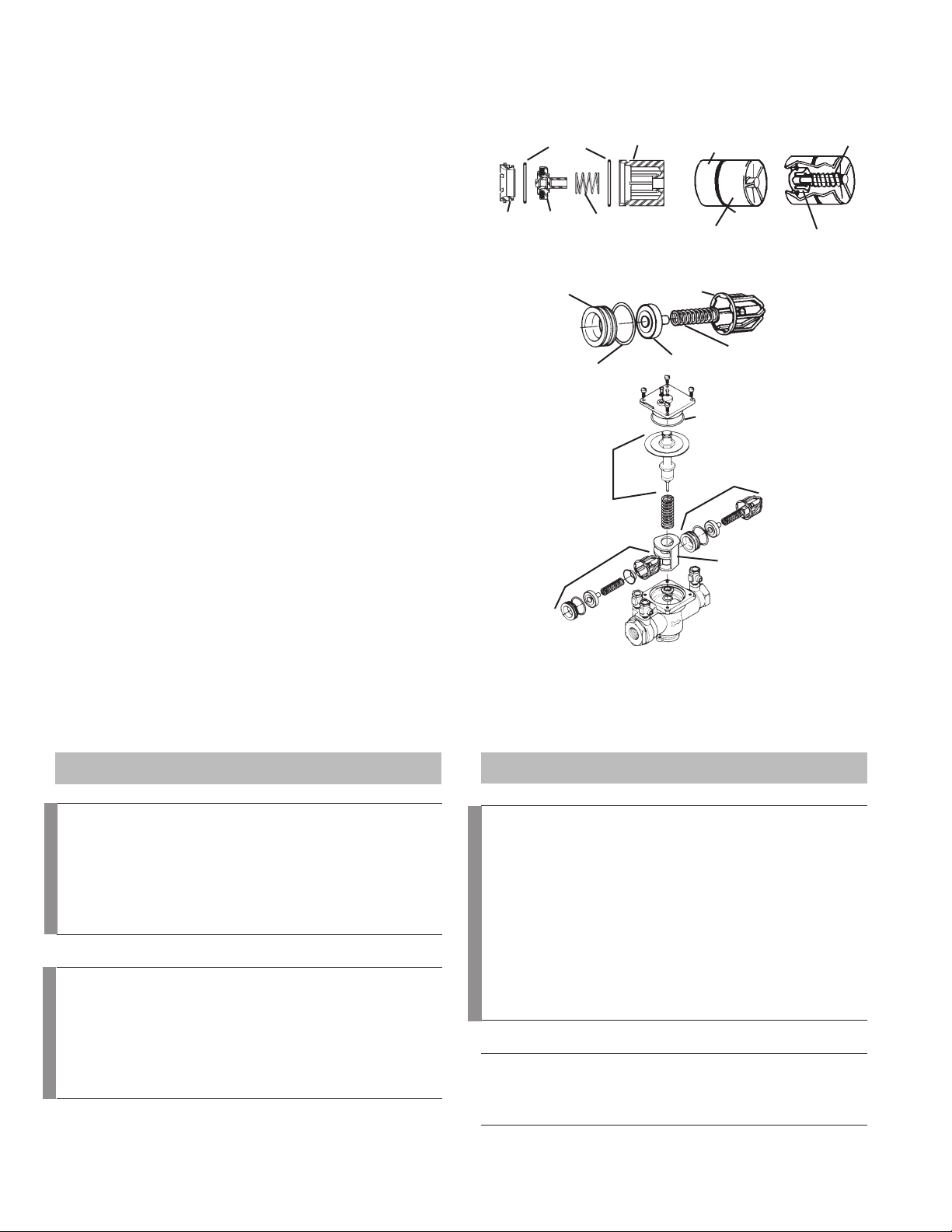
Cover O-ring
Retainer
Second Check Assembly
First Check Assembly
Relief
Valve
Module
CHECK ASSEMBLY 3⁄4" M3
O-ring
Seal
Spring
Disc
Seat
Check
Cage
CHECK ASSEMBLY 1⁄4" – 3⁄4"
Injection Molded
Acetal Resin
O-ring Seal
Stainless Steel
Spring
Silicone Seal
1st Check
Module
CHECK ASSEMBLY 1" - 2" (25 – 50mm)
Seat
Seat O-ring Disc Assembly
Spring
Check Cage
Check Valve Kits
1⁄4" – 2" (8 – 50mm)
When ordering, specify Ordering Code, Kit number and Valve Size.
ORDERING CODE KIT NO. SIZE
in. mm
Check Rubber Parts
0887293 RK 009 RC3 1⁄4, 3⁄8, 1⁄28, 10, 15
0887003 RK 009M2 RC3 3⁄420
0888522 RK 009M3 RC3 3⁄420
0887507 RK SS009 RC1 1⁄215
0887517 RK SS009M2 RC1 3⁄420
0888595 RK SS009M3 RC1 1⁄4– 3⁄48-20
0887017 RK 009 RC1 3⁄4– 1 20-25
0887527 RK SS009 RC1 1 25
0887791 RK 009M2 RC1 1 25
0887508 RK SS009 RC2 1⁄215
0887518 RK SS009M2 RC2 3⁄420
0888596 RK SS009M3 RC2 1⁄4– 3⁄48-20
0887180 RK 009 RC2 3⁄4– 1 20-25
0887528 RK SS009 RC2 1 25
0887792 RK 009M2 RC2 1 25
Kit consists of: Disc, Cover O-ring and Seat O-ring.
Retainers
1047053 99AB47 1⁄4, 3⁄8, 1⁄28, 10, 15
1047394 99BA47 M2-M3 3⁄420
1047001 99FA47 11⁄4– 2 32-50
1047001 99FA47 M1, 2" M2 11⁄4– 2 32-50
1047401 99EA47 M2 11⁄4– 11⁄232-40
LEAD FREE*
ORDERING CODE KIT NO. SIZE
in. mm
First Check Kits
0887291 RK 009 CK1 1⁄4, 3⁄8, 1⁄28, 10, 15
0887505 RK SS009 CK1 1⁄215
0887000 RK 009M2 CK1 3⁄420
0887515 RK SS009M3 CK1 1⁄4– 3⁄48-20
0888520 RK 009M3 CK1 3⁄420
0887005 RK 009 CK1 3⁄4– 1 20-25
0887009 RK 009 CK1SS 3⁄4– 1 20-25
0887525 RK SS009 CK1 1 25
0887789 RK 009M2 CK1 1 25
Kit consists of: Check assembly and Cover O-ring.
Second Check Kits
0887292 RK 009 CK2 1⁄4, 3⁄8, 1⁄28, 10, 15
0887506 RK SS009 CK2 1⁄215
0887001 RK 009M2 CK2 3⁄420
0887516 RK SS009M3 CK2 1⁄4– 3⁄48, 10, 15
0888521 RK 009M3 CK2 3⁄415
0887007 RK 009 CK2 3⁄4– 1 15-25
0887011 RK 009 CK2SS 3⁄4– 1 15-25
0887526 RK SS009 CK2 1 25
0887790 RK 009M2 CK2 1 25
Kit consists of: Check assembly and Cover O-ring.
LEAD FREE*
LEAD FREE*
1⁄4" – 1" (8 – 25mm)
6
*The wetted surface of this product contacted by consumable
water contains less than 0.25% of lead by weight.
Servicing First & Second Check Valves
Series 009 and LF009
1⁄4" – 1" (8 – 25mm)