KTR Kupplungstechnik
GmbH
D-48407 Rheine
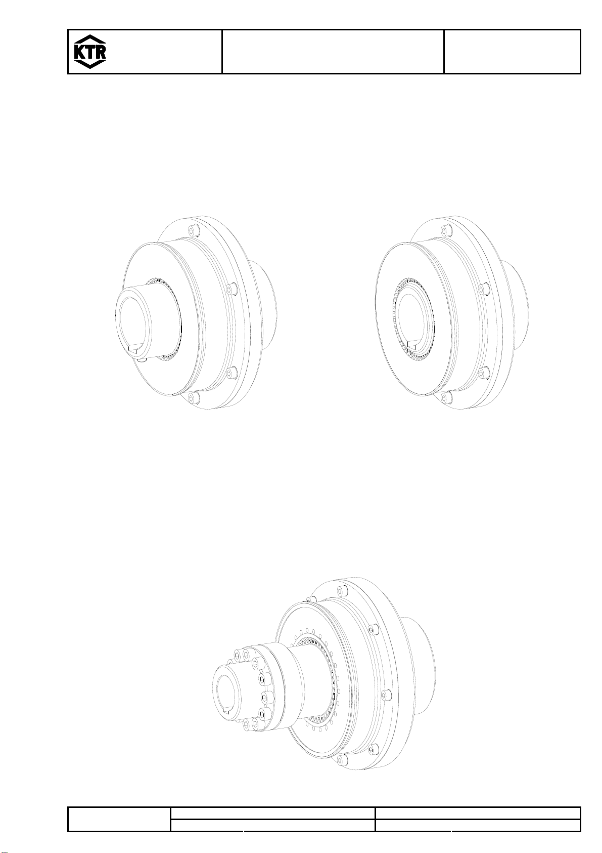
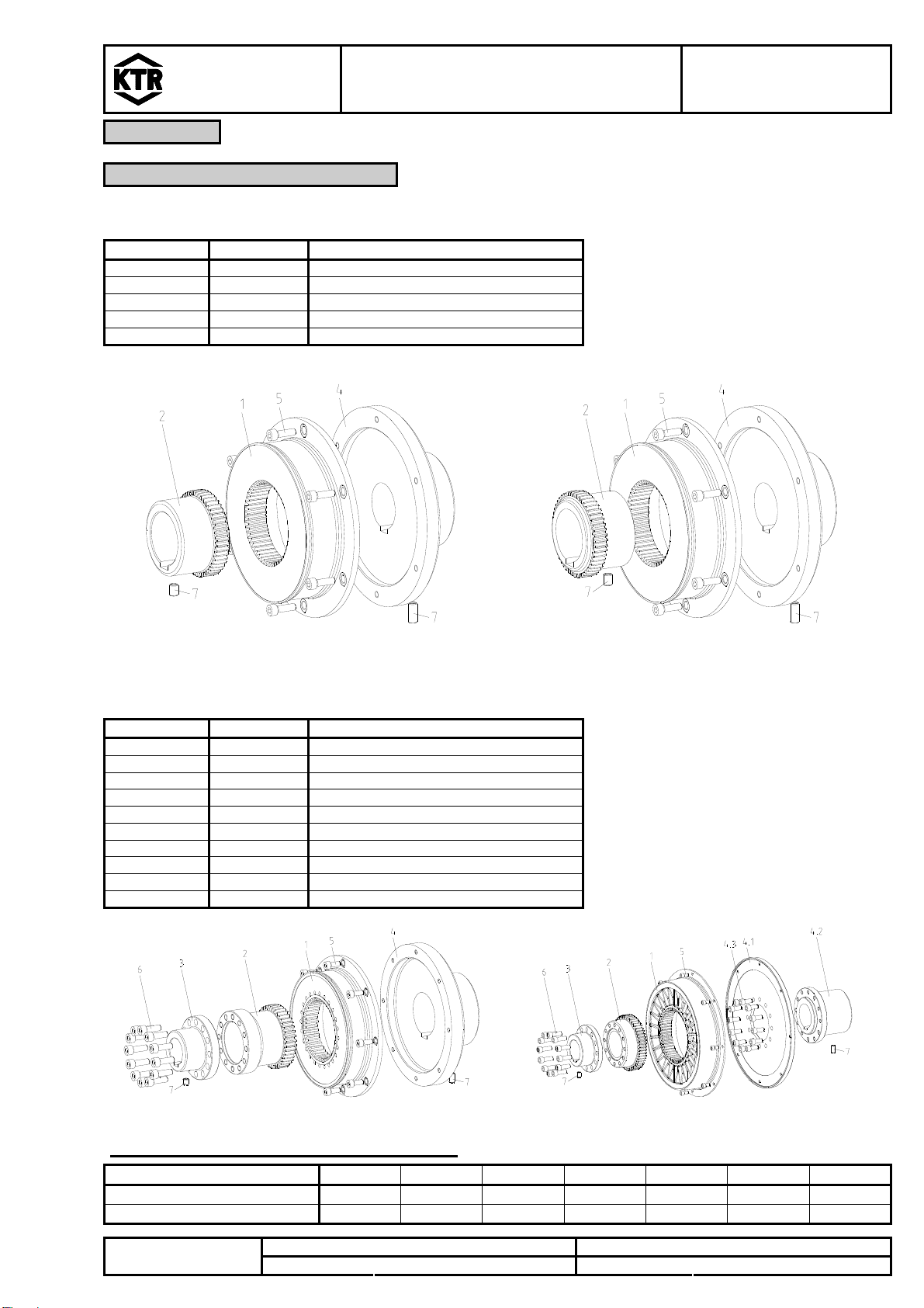
BoWex-ELASTIC®
Operating/Assembly Instructions
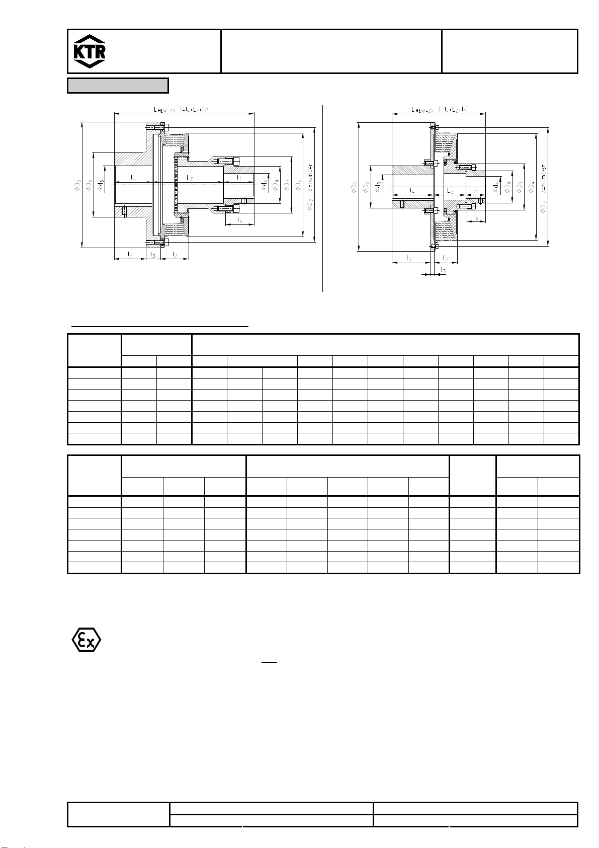
Type HEW and HEW-ZS
KTR-N
Sheet:
Edition:
40114 EN
5 of 20
5
Drawn: 08.11.11 Pz/Hk Replaced for: KTR-N valid from 08.04.04Please note protection
mark ISO 16016. Verified: 09.11.11 Pz Replaced by:
2 Hints
2.1 Coupling Selection
!
CAUTION!
For a continuous and troublefree operation of the coupling it must be designed according to
the selection instructions (according to DIN 740 part 2) for the particular application
(see BoWex-ELASTIC®catalogue).
If the operating conditions (performance, speed, changes on engine and machine) change,
the coupling selection must be checked again.
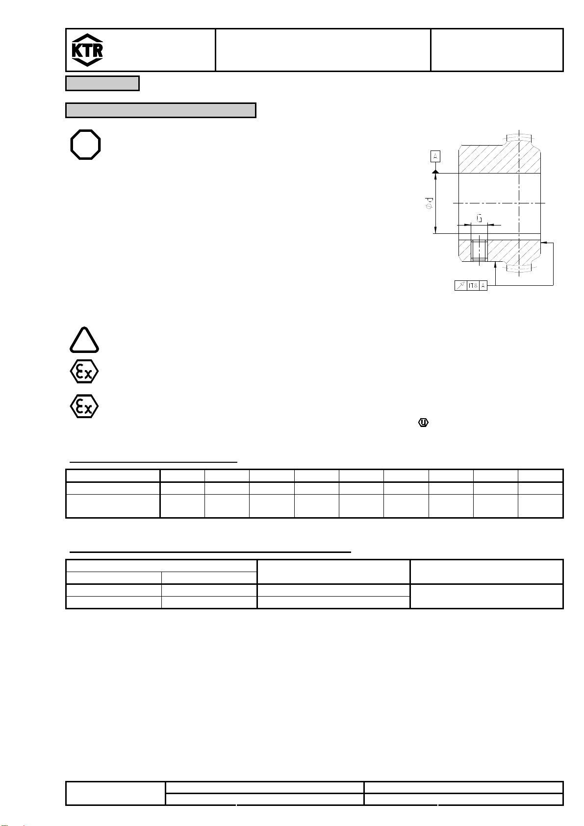
Please make sure that the technical data regarding torque only refer to the elastomer part.
The transmissible torque of the shaft/hub connection must be checked by the orderer, and he
is responsible for the same.
For drives with dangerous torsional vibration (drives with periodical load on torsional vibration) it is necessary to
make a torsional vibration calculation to ensure a perfect selection. Typical drives with dangerous torsional
vibration are e. g. drives with diesel engines, piston pumps, piston compressors etc. On request KTR will perform
the coupling selection and the torsional vibration calculation.
2.2 General Hints
Please read through these mounting instructions carefully before you set the coupling into operation.
Please pay special attention to the safety instructions!
The BoWex-ELASTIC®coupling is suitable and approved for the use in hazardous areas. When
using the coupling in hazardous areas please observe the special hints and instructions regarding
safety mentioned in enclosure A.
The mounting instructions are part of your product. Please keep them carefully and close to the coupling.
The copyright for these mounting instructions remains with KTR Kupplungstechnik GmbH.
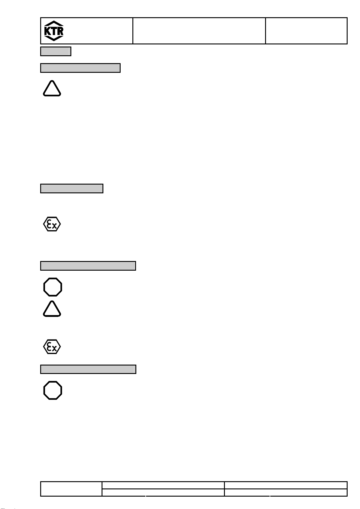
2.3 Safety and Advice Hints
STOP DANGER! Dangerofinjurytopersons.
! CAUTION! Damagesonthemachinepossible.
A TTE NT IO N! Pointing to important items.
PRECAUTION! Hintsconcerningexplosionprotection.
2.4 General Hints of Danger
STOP
DANGER!
With assembly, operation and maintenance of the coupling it has to be made sure that the
entire drive train is protected against unintentional engagement. You can be seriously hurt
by rotating parts. Please make absolutely sure to read through and observe the following
safety instructions.
All operations on and with the coupling have to be performed taking into account "safety first".
Please make sure to disengage the power pack before you perform your work.
Protect the power pack against unintentional engagement, e. g. by providing hints at the place of engagement
or removing the fuse for current supply.
Do not touch the operation area of the coupling as long as it is in operation.
Please protect the coupling against unintentional touch. Please provide for the necessary protection devices
and caps.