Pribusin RCI-200 series User manual

Manufacturers of Process
Controls and Instrumentation
Instruction Manual
Model:
Serial #:
Power:
Function:
XXX=MDM Modem Dial-Up
Communication:
RCI-200-XXX
(If special or required)
24 VDC
2 “Dry” Contacts and 2 Analog Inputs
Input:
Remote Control Signal Interface
XXX=SER: RS-232/485
Output: 2 Form ‘C’ Contacts and 2 Analog Outputs
117VAC, 50/60Hz
XXX=RF9: 900 Mhz Wireless
XXX=FSK: Leased Line
XXX=R : 2.4 Ghz WirelessF2
For Technical Assistance And Questions Call
USA: (231) 788-2900 CANADA: (905) 660-5336

Restocking Policy
Page v
Warranty Policy
All product returned to Pribusin Inc. in prime condition (not
damaged, scratched or defaced in any way) within seven (7)
months from the original date of shipment is subject to a 50%
restocking charge. All product must be accompanied by a
Return Authorization number (RA number) which must be
obtained from Pribusin Inc. prior to returning any product.
After seven (7) months from the original date of shipment,
products cannot be returned for restocking.
Custom designed products, modified products or all non-
standard products may not be returned for restocking.
Pribusin Inc. warrants equipment of its own manufacture to be
free from defects in material and workmanship, under normal
conditions of use and service, and will replace any component
found to be defective, on its return to Pribusin Inc.,
transportation charges prepaid, within one year of its original
purchase. Pribusin Inc. will extend the same warranty
protection on equipment, peripherals and accessories which is
extended to Pribusin Inc. by the original manufacturer. Pribusin
Inc. also assumes noliability, expressed or implied, beyond its
obligation to prelace any component involved. Such warranty
is in lieu of all other warranties, expressed or implied.
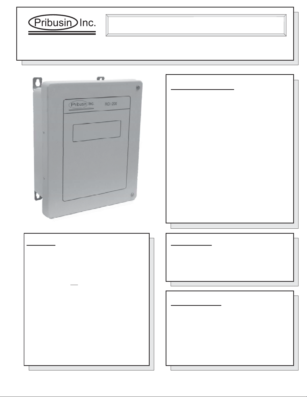
Function:
The RCI-200-SER is a bi-directional remote
communication system that exchanges the status of 2
dry contact inputs and 2 analog inputs between a master
and remote unit or a PC. A basic system consists of A)
one master station and one remote station each with 2
dry contact and 2 analog inputs and 2 'C' relay contact
and analog outputs B) several remote stations and
one PC.
In systemA), the master unit can interrogate a remote.
In system B), a PC can interrogate several remote units.
LabVIEW & drivers are provided for user software
development on Pc’s.
OR
Connection:
Units are connected via a class 'C' line (Dial-up or
leased). Regular J11 Phone Jacks make for easy
installation. When connecting units on a PBX system
make sure it can accept analog modem transmissions.
Serial systems connect via standard modem cable.
Standard Features:
Bi-directional Communication using a RS232/485
Serial Bus Link
2 Dry Contact and 2 Analog Inputs
2 'C' Relay Contacts and 2 Analog Outputs
No Calibration Required
Microprocessor Controlled for High Accuracy
Power: 117 VAC 50/60 Hz (Optional 24 VDC)
High Noise Rejection
Specifications:
Transmission Medium: RS232/485
BAUD Rate: 2400 BAUD typ., 9600, 14.4K available
Operating Temperature: -20 Deg.C. to +50 Deg.C.
Relay Contacts: 10A 1/8Hp @ 125VAC
6A 1/8Hp @ 277VAC
Power: 117 VAC, 60/50 Hz
(24VDC Available)
Enclosure: NEMA4X (NEMA12 available as an option)
Model: RCI-200-SER
Remote Control Signal Interface
RS232/485
Page J24
Manufacturers of Process
Controls and Instrumentation
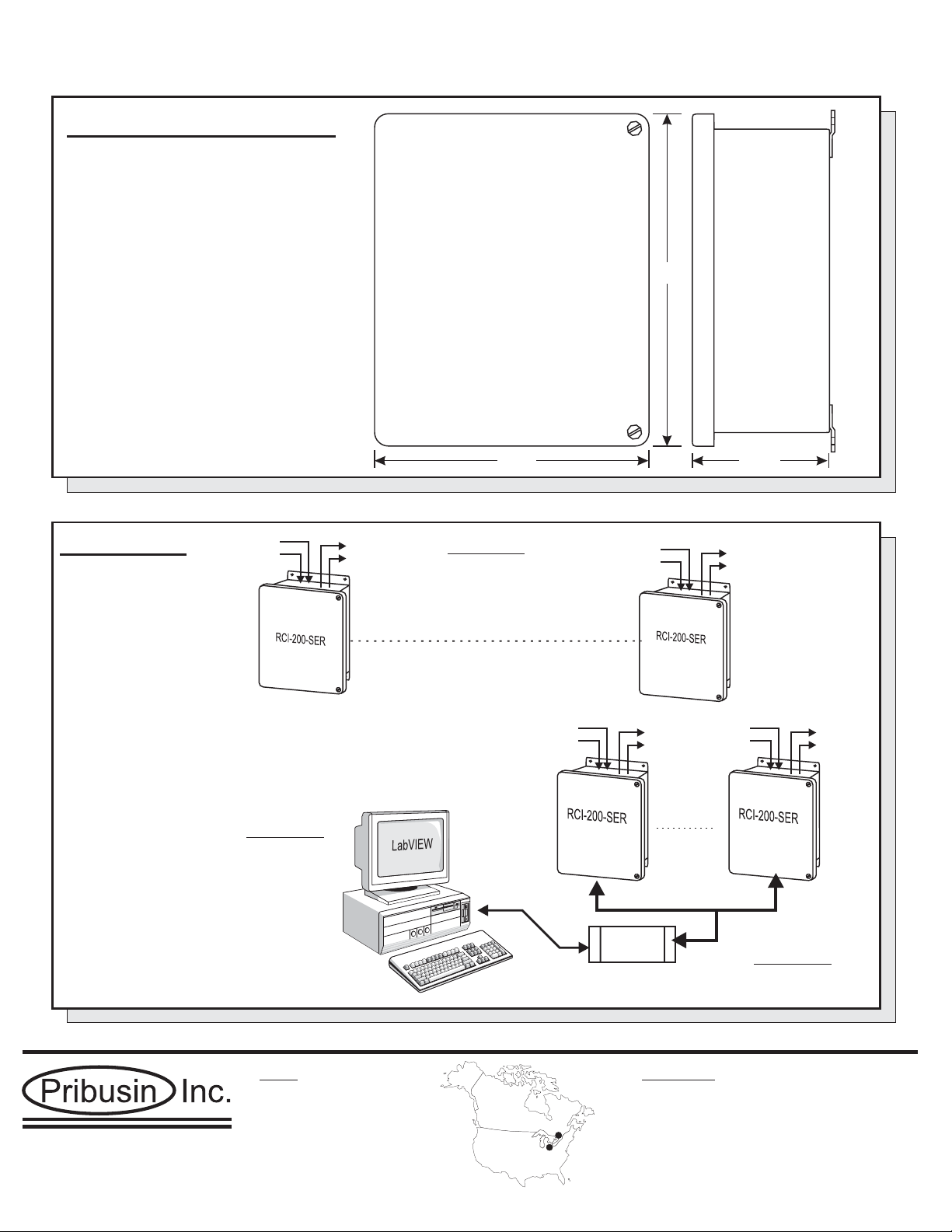
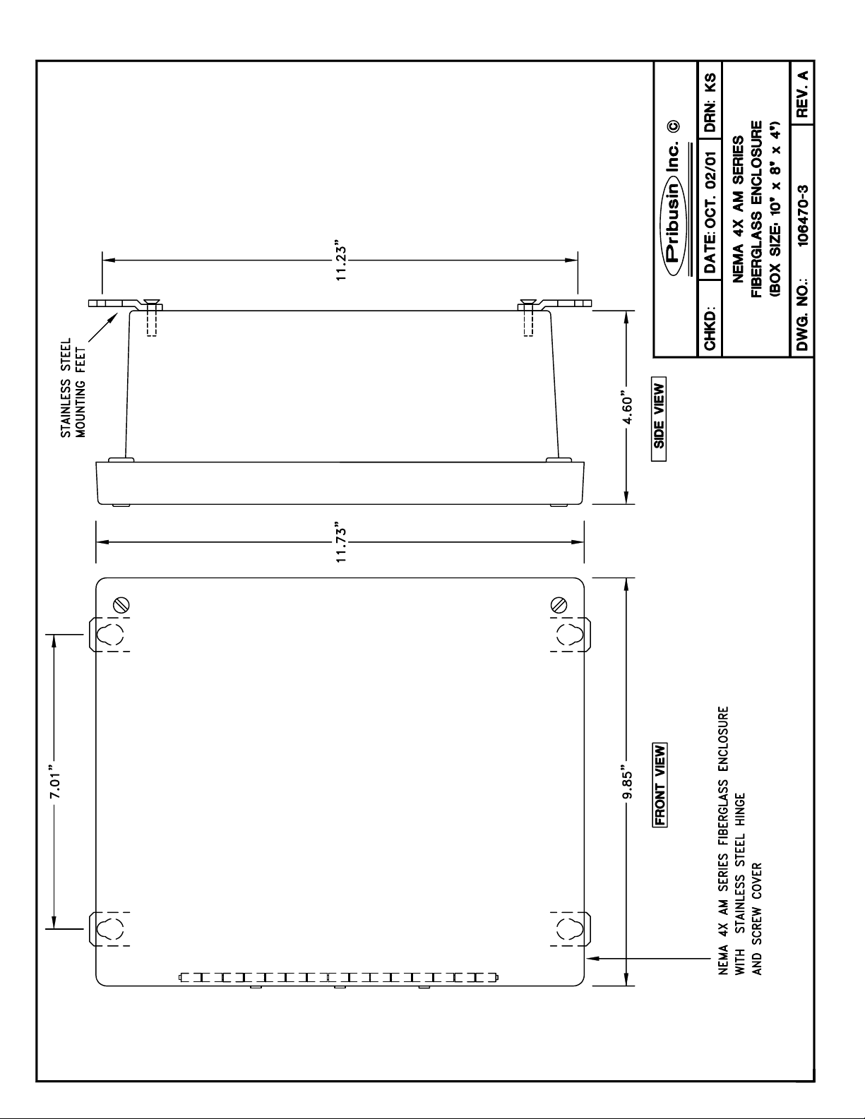
Enclosures & Dimensions:
Connection:
Page J24
RCI-200-SER
2 Analog
2 Contact
2 Analog
2 Contact
2 Analog
2 Contact
2 Analog
2 Contact
Serial Link (-SER option)
2 Analog
2 Contact
2 Analog
2 Contact
2 Analog
2 Contact
2 Analog
2 Contact
RS485/RS232
Converter
(232/485COM)
RS-232
RS-485
up to 128*
devices
RS-485 Bus
RS-232
System A
System B
System C
* Additional Signal Booster(s) required for 32+ devices (see SPB-485)
Manufactured By:
11.25”
9.25” 4.5”
www.pribusin.com
CANADA:
Pribusin Inc.
101 Freshway Dr. Unit 57
Concord, Ontario, L4K 1R9
Ph: (905) 660-5336
Fx: (905) 660-4068
USA:
Pribusin Inc.
743 Marquette Ave.
Muskegon, MI 49442
Ph: (231) 788-2900
Fx: (231) 788-2929
Rev.B Subject to change without notice

..\Manuals\RCI-200-SER Page 1 of 12
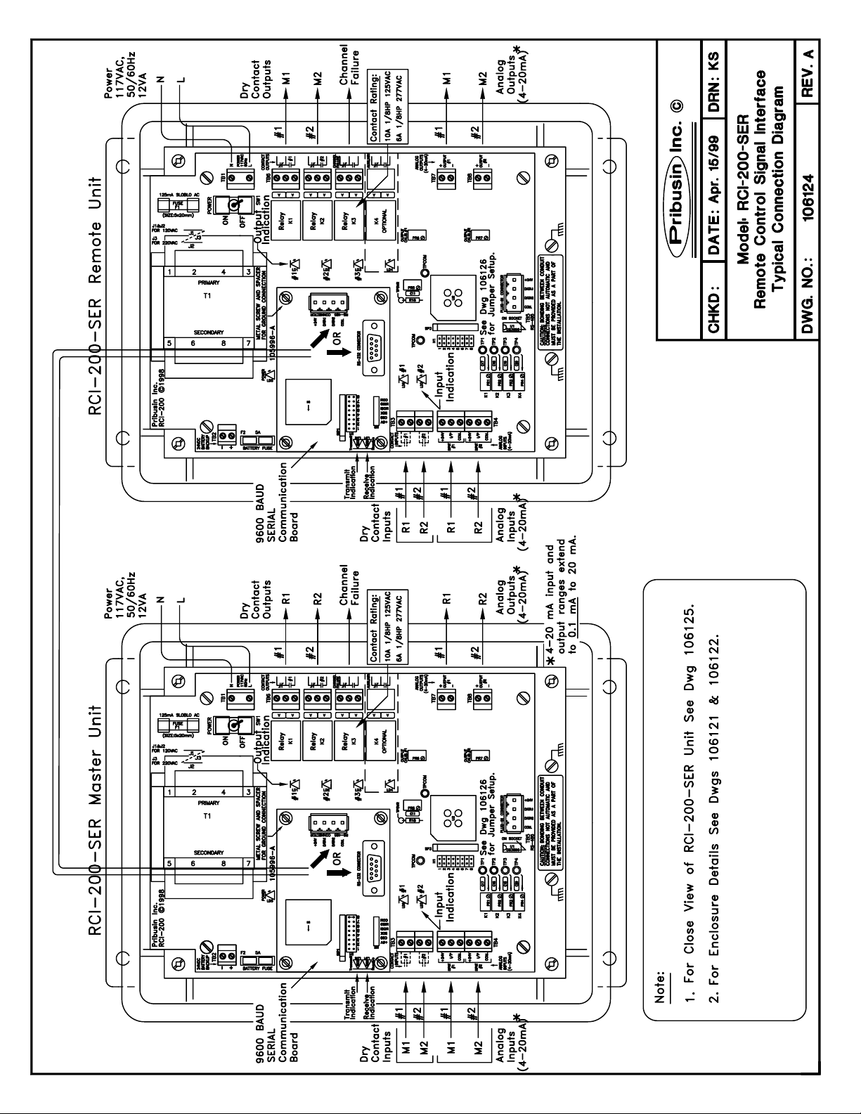
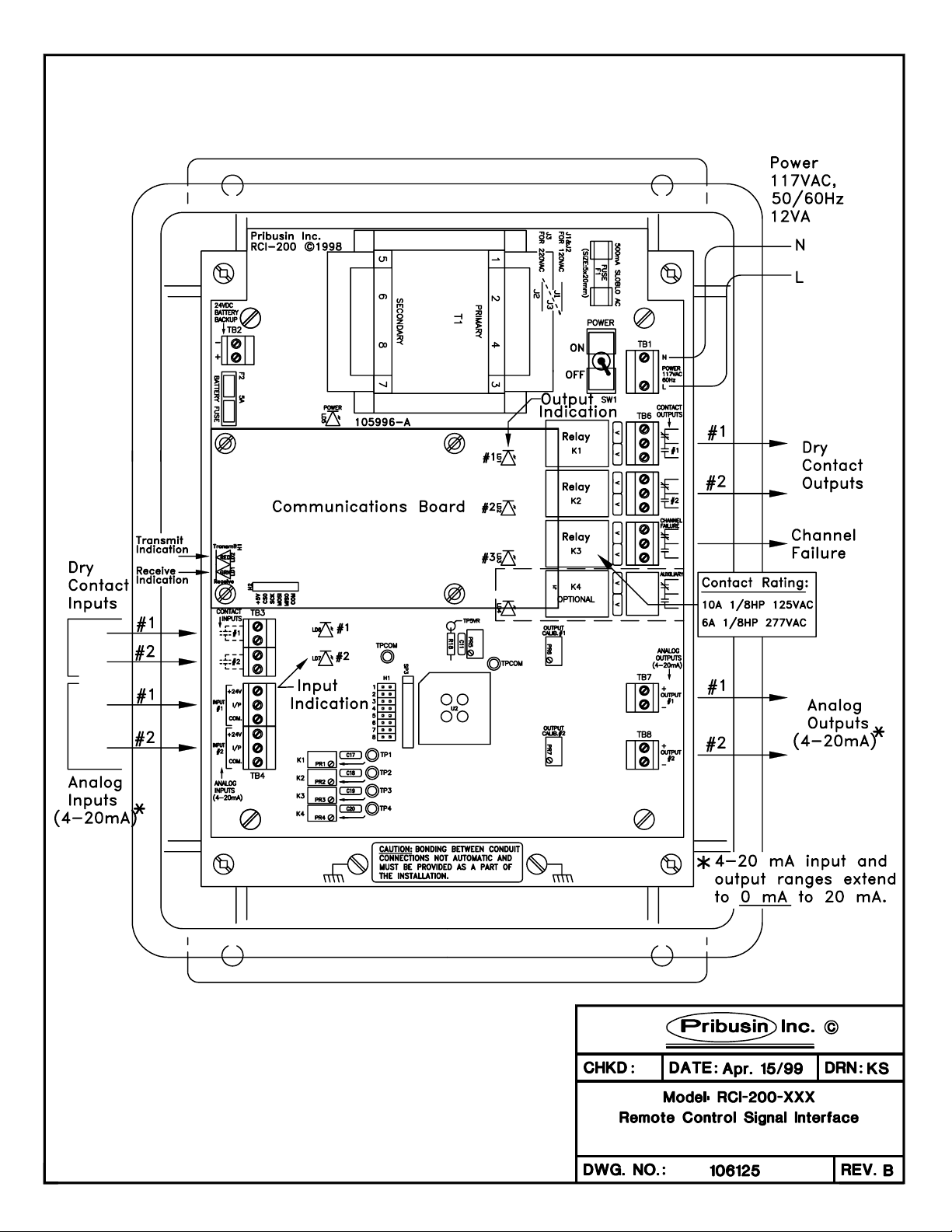
RCI-200 Connections:
The RCI-200 is the main board of an RCI-200-XXX Telemetry system. It provides the input and output
signal connections as well as the power supply for the unit. A separate communications board is
added to the RCI-200 to allow it to communicate with other units. This communications board may
have its own configuration that is in a separate section of this manual. The following configuration
applies only to the RCI-200 board and is common to all communications interfaces.
AC Power & Fuse:
The RCI-200 is typically powered from 120VAC and protected by a 500mA
SLOBLO fuse. It can be wired for 240VAC operation by removing (de-
soldering) power jumpers J1 & J2 and installing (soldering) jumper J3.
When changing the RCI-200 to 240VAC power make sure to change the fuse
to half of its value, 250mA. This is important since at 240VAC the RCI-200
requires only half the current as if it were powered from 120VAC. Proper
protection is only achieved by reducing the fuse value as mentioned above.
DC Power & Battery Backup:
The RCI-200 may also be powered from a 24VDC source which could be a
battery or a DC power supply. The 24VDC power input is polarity protected
with a fuse to prevent damage to the RCI-200 by inadvertent reverse polarity.
A DC fuse provision is also provided if this power option is utilized. Insert a
5A automotive type blade fuse into the Battery Fuse socket.
..\Manuals\RCI-200-SER Page 2 of 12
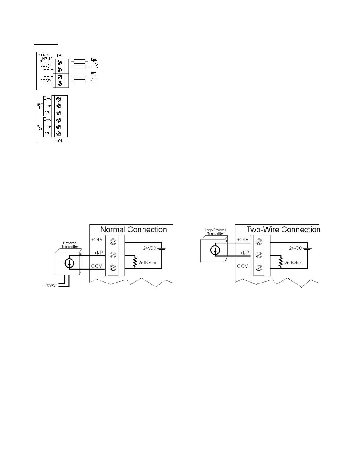
Inputs:
The RCI-200 has two dry contact inputs and two 0-20mA inputs. The dry
contact inputs are excited with 24VDC and will source approximately 20mA
when the contact is closed. A red LED lights up when a contact input is
closed.
The analog inputs are configured as 0-20mA inputs and have a 250Ωinput impedance.
Each input terminal has three connections: +24V, I/P, COM. The +24V power output
may be used to power field transmitters. Up to 500mA may be used to power a
transmitter. The input signal is connected to I/P(+) and COM(-).
Analog inputs are connected to the RCI-200 in two fashions: 1) Normal (3-wire connection) or 2) two-
wire connection. On a 3-wire connected input, an external power supply or the +24V power output
terminal of the RCI provides power to the field transmitter. The field transmitter has a current source
that provides the 4-20mA signal back to the RCI-200. If using the power supply of the RCI-200, the
field transmitter may draw up to 125mA. A total of 1A is available to power up to 2 field transmitters.
On a 2-wire connected input, the field transmitter receives power from the RCI-200 and superimposes
the signal onto the power return path. A maximum of 20mA will flow in such a connection. Make sure
to consult the field transmitter manual to determine how to connect it to the RCI-200.
..\Manuals\RCI-200-SER Page 3 of 12
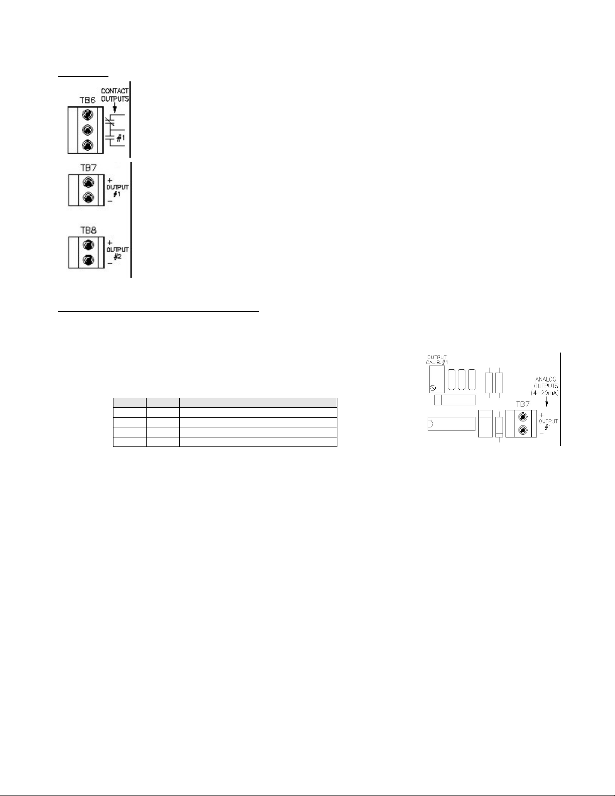
Outputs:
The RCI-200 has two form ‘C’ relay contact outputs and two 0-20mA analog outputs.
The relay contacts are capable of switching 120VAC, 10A or 240VAC, 6A. An energy
absorbing varistor is installed across each contact to limit switching transients. A
third relay contact acts as a communications fail indicator. If no communication
occurred within 30 seconds, this relay contact will energize. Upon re-established
communication this relay will de-energize again.
The two analog outputs are typically configured as 0-20mA outputs and can drive into
a 1000Ωload each, provided that the power supply to the unit is not below 24VDC.
The outputs are not isolated from each other or from the inputs. Care must be taken
when connecting the outputs to different devices so that no inadvertent ground loops
are established.
Output Calibration & Input Testing:
The outputs on the RCI-200 are factory calibrated and should not require any adjustments. To
check the calibration of the outputs and relays use jumpers H1-7 & H1-8 as shown below to set them to
known states. If an output should require some adjustment, insert
jumper H1-8 only and turn the OUTPUT CALIB. trim pot until the output
reads 20mA.
If both jumpers are IN the analog and contact inputs are passed straight through to the analog and
relay outputs. This may help in troubleshooting input and output signals.
Make sure both jumpers are removed before resuming normal operation.
H1-7 H1-8 Function
OUT OUT Normal Operation
OUT IN Outputs=20mA, Relays=Energized
IN OUT Outputs=0mA, Relays=De-energized
IN IN Outputs=Inputs, Relays=Contact Inputs
..\Manuals\RCI-200-SER Page 4 of 12
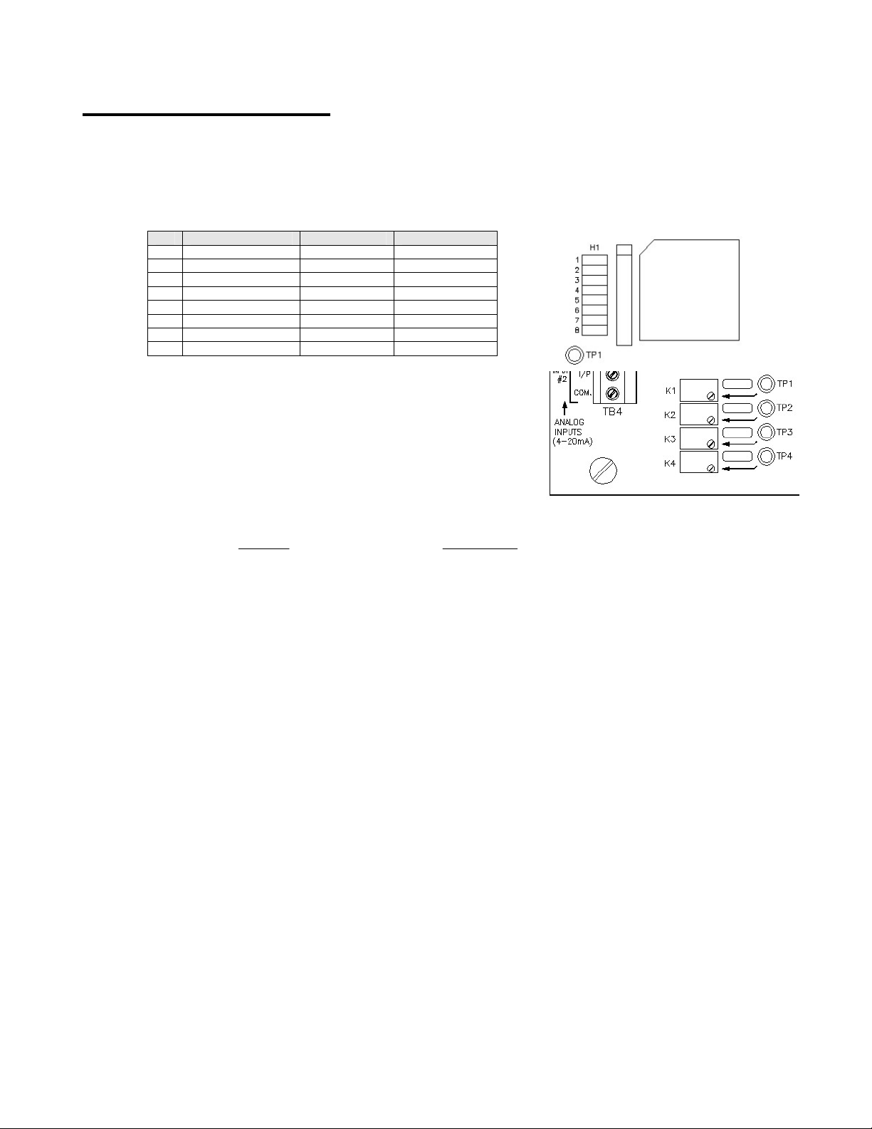
RCI-200 Configuration:
The RCI-200 requires no configuration other than for its communication fail operation. In the event of a
communications failure on the communications board, the RCI-200 can be set up to take various
actions on its outputs. This may be desirable in order to place connected devices into a safe operating
mode. By default factory setting, all outputs remain at their last known state if a communications failure
occurs.
* If H1-3=IN then analog output #1 will ramp to the
setting of K1 and analog output #2 will ramp to the
setting of K2. Both outputs will change at a rate
determined by the setting of K3. The settings of the
trim pots can be read on test points TP1,2,3 using a
voltmeter. The test points read a voltage of 0-5V for
a 0-100% adjustment.
where, Output = 0-20 (mA) and Ramp Rate = 0-60 (seconds) (5 sec. minimum)
H1- Function OUT IN
1 Relay Fail Mode No Change See H1-2
2 Relay Fail Status De-Energize Energize
3 Output Fail Mode No Change Ramp to K1/K2*
4
5
6
7 I/O Calibration
8 I/O Calibration
Volt
Output
TP 5
20
2,1 ×= Volt
RampRate
TP 5
60
3×=

..\Manuals\RCI-200-SER Page 5 of 12
SERIAL Communication Option:
The -SER communications option for the RCI series utilizes either an RS-232 or RS-485 link to
exchange the signal data between a host and its remote(s). There are three types of Topologies that
can be configured: 1) Point-to-Point, 2) Host-to-Multipoint and 3) PC-to-Multipoint
In a Point-to-Point topology one
host communicates with one remote.
The two exchange all their signals
with one another. The remote is
configured as remote #1 even
though it is the only remote in the
system.
In a Host-to-Multipoint topology
one host communicates to several
remotes. Each remote is assigned
an address (1,2,3, etc.) so that the
host may distinguish between them.
There may at most be as many
remotes as there are inputs &
outputs on the host.
For example, an RCI-200 system,
having two analog/contact inputs
and outputs, may communicate with
up to two remotes each having one analog/contact input and output. In this case all #1 inputs and
outputs on the host correspond to the #1 inputs and outputs on remote #1 and all #2 inputs and
outputs on the host correspond to the #1 inputs and outputs on remote #2.
In a PC-to-Multipoint topology one
PC (or PLC) host communicates
with one or more remotes via
MODBUS ASCII protocol. Software
that runs on the PC (or PLC) takes
the place of the Host and can
directly read and write the inputs and
outputs of the remote units. Each
remote is assigned an address
(1,2,3, etc.) so that the host may
distinguish between them.

..\Manuals\RCI-200-SER Page 6 of 12
SERIAL Configuration:
All SERIAL configurations are done via
two banks of DIP switches. SW1-1, -2, &
-3 assigns the remote address from 1 to 8
using a binary encoding scheme. SW2
assigns the Topology, Channel Numbers
and Host/Remote Mode. The switches
are located on the communications board
just above the main circuit board. They
are a slanted rocker type that flips up for
OFF and down for ON.
The -SER communication board has two banks of 8-position DIP switches: SW1 and SW2. The
function of these switches is slightly different for a host unit and a remote unit.
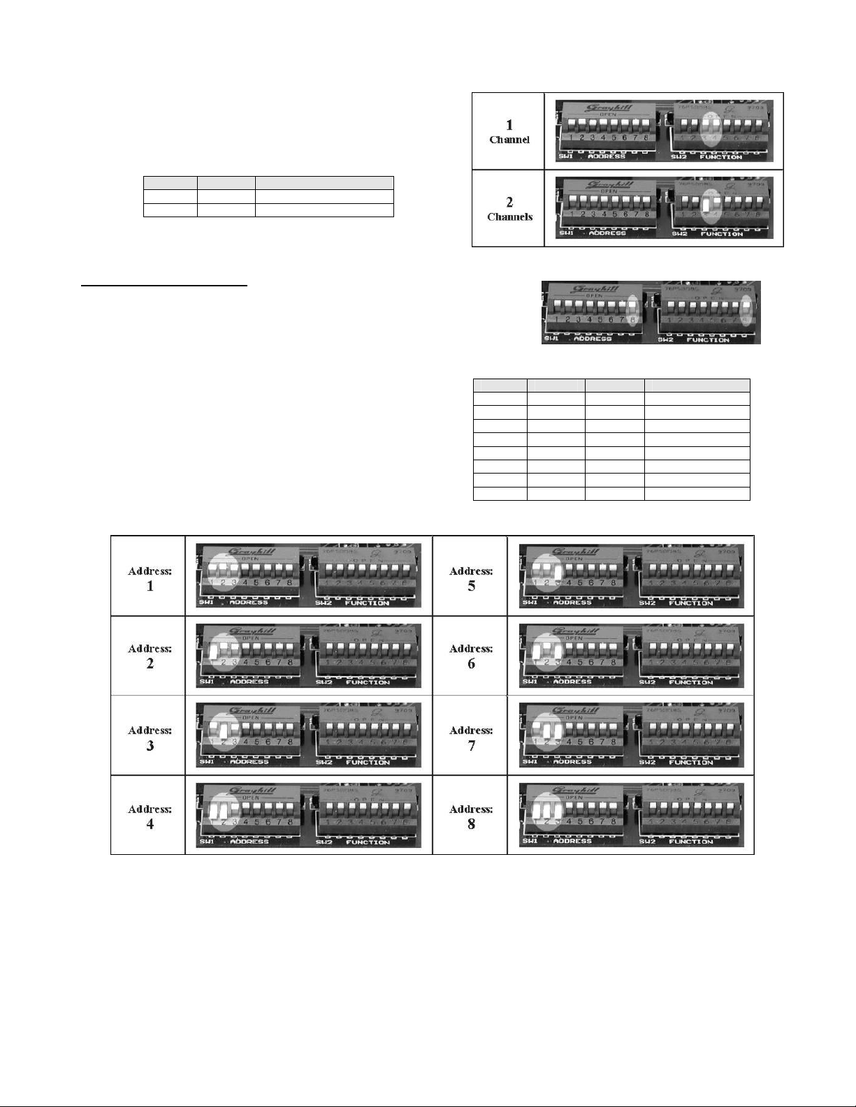
Host Configuration:
To make an RCI-200 operate as a host unit, make sure that
SW2-8 is flipped down.
Next, set the number of remotes that the host is to
communicate with using SW1-1, -2, -3. These
switches are binary encoded as shown in the chart to
the right.
SW1-1 SW1-2 SW1-3 # of Remotes
UP UP UP 1
DOWN UP UP 2
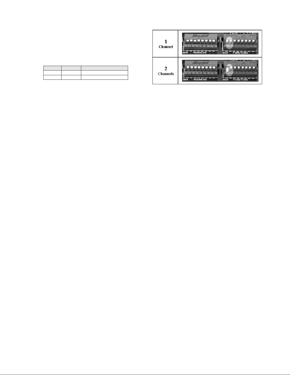
Next, set the number of channels of each remote
using SW2-1, -2. One channel is considered 1 analog
input/output plus 1 contact input/output. Hence an RCI-
200 can have at most 2 channels.
SW2-1 SW2-2 Channels on Remotes
UP UP 1
DOWN UP 2
SW1- HOST REMOTE
1 # of Remotes Remote Address
2 # of Remotes Remote Address
3 # of Remotes Remote Address
4
5
6
7
8
SW2- HOST REMOTE
1 # of Channels on each Remote # of Channels on this Remote
2 # of Channels on each Remote # of Channels on this Remote
3 # of Channels on Host
4 # of Channels on Host
5
6
7
8 Host / Remote Select Host / Remote Select
..\Manuals\RCI-200-SER Page 7 of 12
Remote Configuration:
To make an RCI-200 operate as a REMOTE unit, make sure that
SW2-8 is flipped up.
Next, set the remote address using SW1-1, -2, &
-3. This switch is binary encoded and you will
have to convert the remote address to binary first.
SW1-1 SW1-2 SW1-3 Remote Address
UP UP UP 1
DOWN UP UP 2
UP DOWN UP 3
DOWN DOWN UP 4
UP UP DOWN 5
DOWN UP DOWN 6
UP DOWN DOWN 7
DOWN DOWN DOWN 8
Next, set the number of channels of the host using
SW2-3, -4. An RCI-200 can at most have 2 channels.
This is the number of channels that will be exchanged
between the host and each remote.
SW2-3 SW2-4 Channels on Host
UP UP 1
DOWN UP 2
..\Manuals\RCI-200-SER Page 8 of 12
Next, set the number of channels on this
remote using SW2-1, -2. One channel is
considered 1 analog input/output plus 1 contact
input/output. Hence an RCI-200 can have at most
1 channel.
SW2-1 SW2-2 Channels on Remote
UP UP 1
DOWN UP 2
..\Manuals\RCI-200-SER Page 9 of 12
PC or PLC Interfacing using MODBUS ASCII:
The RCI-200-SER can communicate directly to a PC or PLC using MODBUS ASCII protocol.
Numerous off-the-shelf software packages have built-in MODBUS support. The following information
provides the MODBUS specific parameters necessary to configure the PC/PLC software.
Message Format
1) RCI-XXX-MDM = 2400 Baud
ASCII Framing
Start Address Function Data LRC End
1 Char
:
2 Chars 2 Chars n Chars 2 Chars 2 Chars
CR,LF
MODBUS Registers
The functions and registers listed in the table below are the only ones implemented on all RCI products
at this time.
Description (Function) RCI-100-XXX RCI-200-XXX RCI-400-XXX RCI-800-XXX
Read Relay Status (01) 00001 00001-00002 00001-00004 00001-00008
Read Digital Input (02) 10001 10001-10002 10001-10004 10001-10008
Read Analog Output (03) 40001 40001-40002 40001-40004 40001-40008
Read Analog Input (04) 30001 30001-30002 30001-30004 30001-30008
Set Relay Status (05) 00001 00001-00002 00001-00004 00001-00008
Set Analog Output (06) 40001 40001-40002 40001-40004 40001-40008
Set Multiple Relays (0F) 00001 00001-00002 00001-00004 00001-00008
Set Multiple Analog Out (10) 40001 40001-40002 40001-40004 40001-40008
Speed Start Data Parity Stop
96001) 1 7 E 1

..\Manuals\RCI-200-SER Page 10 of 12
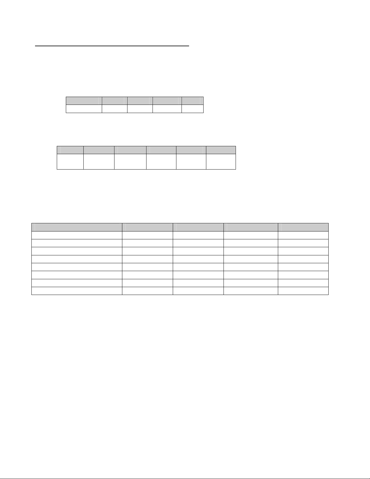
Point-to-Point Communication
Communication between one host and one remote is called point-to-point.
Example 1: An RCI-100 Host communicating with an RCI-100 Remote
Example 2: An RCI-200 Host communicating with an RCI-200 Remote
RCI-200 (Host) RCI-200 (Remote)
Host Channels: 2Remote Channels: 2
Number of Remotes: 1Address: 1
Channels on Remotes: 2
Example 3: An RCI-400 Host communicating with an RCI-400 Remote
RCI-400 (Host) RCI-400 (Remote)
Host Channels: 4Remote Channels: 4
Number of Remotes: 1Address: 1
Channels on Remotes: 4
Example 4: An RCI-800 Host communicating with an RCI-800 Remote
RCI-800 (Host) RCI-800 (Remote)
Host Channels: 8Remote Channels: 8
Number of Remotes: 1Address: 1
Channels on Remotes: 8
RCI-100 (Host) RCI-100 (Remote)
Host Channels: 1Remote Channels: 1
Number of Remotes: 1Address: 1
Channels on Remotes: 1

..\Manuals\RCI-200-SER Page 11 of 12
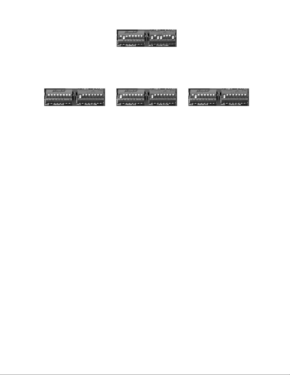
Point-to-Multipoint Communication
Communication between a host and more than one remote is called point-to-multipoint.
Example 1: An RCI-200 Host communicating with (2) RCI-100 Remotes
Example 2: An RCI-400 Host communicating with (2) RCI-200 Remotes
Example 3: An RCI-800 Host communicating with (2) RCI-400 Remotes
Example 4: An RCI-800 Host communicating with (3) RCI-200 Remotes
RCI-200 (Host) RCI-100 (Remote 1) RCI-100 (Remote 2)
Host Channels: 2
Number of Remotes: 2
Channels on Remotes: 1
Remote Channels: 1
Address: 1
Remote Channels: 1
Address: 2
RCI-400 (Host) RCI-200 (Remote 1) RCI-200 (Remote 2)
Host Channels: 4
Number of Remotes: 2
Channels on Remotes: 2
Remote Channels: 2
Address: 1
Remote Channels: 2
Address: 2
RCI-800 (Host) RCI-400 (Remote 1) RCI-400 (Remote 2)
Host Channels: 8
Number of Remotes: 2
Channels on Remotes: 4
Remote Channels: 4
Address: 1
Remote Channels: 4
Address: 2
..\Manuals\RCI-200-SER Page 12 of 12
RCI-800 (Host)
Host Channels: 8
Number of Remotes: 3
Channels on Remotes: 2
RCI-200 (Remote 1) RCI-200 (Remote 2) RCI-200 (Remote 3)
Remote Channels: 2
Address: 1
Remote Channels: 2
Address: 2
Remote Channels: 2
Address: 3
Other manuals for RCI-200 series
2
This manual suits for next models
1
Table of contents
Other Pribusin Recording Equipment manuals


Popular Recording Equipment manuals by other brands


HEIDENHAIN
HEIDENHAIN IOB 49 user manual

Renishaw
Renishaw RMI Installation and user guide

USASPEC
USASPEC BT45-ACU product manual

Vocal Booth To Go
Vocal Booth To Go FlexTee Assembly instructions

4EVAC
4EVAC Impact Controller-Expander User and installation manual

BLACK NOISE
BLACK NOISE DRII Build instructions