Pribusin RCI-400 Series User manual

Manufacturers of Process
Controls and Instrumentation
Instruction Manual
Model:
Serial #:
Power:
Function:
XXX=MDM Modem Dial-Up
Communication:
RCI-400-XXX
(If special or required)
24 VDC
4 “Dry” Contacts and 4 Analog Inputs
Input:
Remote Control Signal Interface
XXX=SER: RS-232/485
Output: 4 Form ‘C’ Contacts and 4 Analog Outputs
117VAC, 50/60Hz
XXX=RFM: 2.4 Ghz Wireless
XXX=FSK: Leased Line
For Technical Assistance And Questions Call
USA: (231) 788-2900 CANADA: (905) 660-5336

Restocking Policy
Page v
Warranty Policy
All product returned to Pribusin Inc. in prime condition (not
damaged, scratched or defaced in any way) within seven (7)
months from the original date of shipment is subject to a 50%
restocking charge. All product must be accompanied by a
Return Authorization number (RA number) which must be
obtained from Pribusin Inc. prior to returning any product.
After seven (7) months from the original date of shipment,
products cannot be returned for restocking.
Custom designed products, modified products or all non-
standard products may not be returned for restocking.
Pribusin Inc. warrants equipment of its own manufacture to be
free from defects in material and workmanship, under normal
conditions of use and service, and will replace any component
found to be defective, on its return to Pribusin Inc.,
transportation charges prepaid, within one year of its original
purchase. Pribusin Inc. will extend the same warranty
protection on equipment, peripherals and accessories which is
extended to Pribusin Inc. by the original manufacturer. Pribusin
Inc. also assumes noliability, expressed or implied, beyond its
obligation to prelace any component involved. Such warranty
is in lieu of all other warranties, expressed or implied.
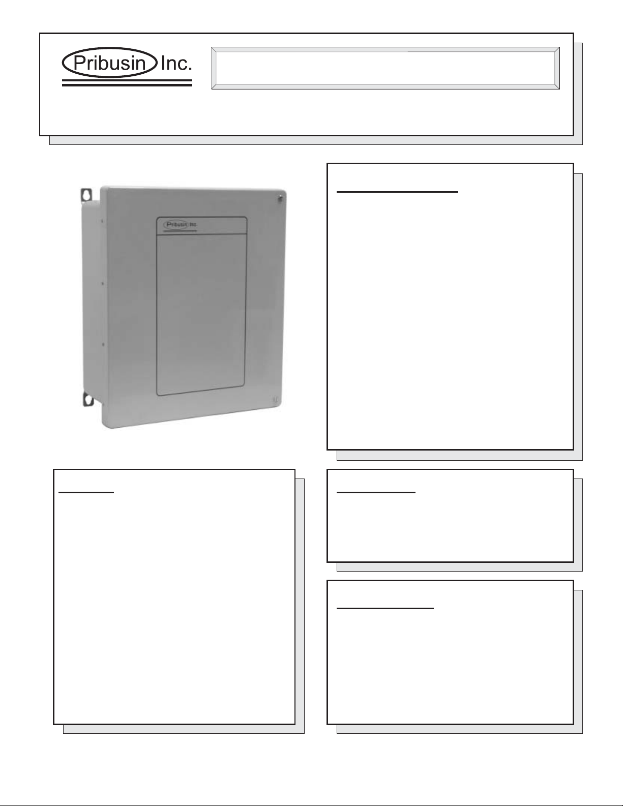
Function:
The RCI-400-FSK is a bi-directional remote
communication system that exchanges the status of 4
dry contact inputs and 4 analog inputs between a master
and remote unit. Both the master and remote unit have
inputs and outputs to allow remote monitoring and
remote control.
Since the master and remote units are connected via
leased telephone line, and hence are ‘always-on’, a
change in signal at one end is transmitted to the other
end with very little delay. This makes this unit ideal for
real-time monitoring of remote tanks, pumps, etc.
The bi-directional operation allows for control signals to
be sent back to the remote site to take action based on
the incoming monitored signal.
This unit may also be used as a remote unit in a multi-
remote system where the master is a multi-channel
device such as the RCI -800.
Connection:
Units are connected via a class 'C' line (Dial-up or
leased). Regular J11 Phone Jacks make for easy
installation. When connecting units on a PBX system
make sure it can accept analog modem transmissions.
Serial systems connect via standard modem cable.
Standard Features:
Bi-directional Communication using a Phone Line
Uses MODBUS Protocol for Reliable Data Transfer
4 Dry Contacts and 4 Analog Inputs
4 'C' Relay Contacts and 4 Analog Outputs
Uses Analog Half-Duplex Leased Telephone Line
No Calibration Required
Microprocessor Controlled for High Accuracy
Power: 117 VAC 50/60 Hz (Optional 24 VDC)
Built-in Overvoltage Protection on Telephone Line
High Noise Rejection
CSA and NRTL Approved (LR51078)
Specifications:
Transmission Medium: Analog Phone Line, Half-Duplex
BAUD Rate: 2400 BAUD
Transmission Output: -6dB max., -8dB typ.
Operating Temperature: -20 Deg.C. to +50 Deg.C.
Relay Contacts: 10A 1/8Hp @ 125VAC
6A 1/8Hp @ 277VAC
Power: 117 VAC, 60/50 Hz
(24VDC Available)
Enclosure: NEMA4X (NEMA12 available as an option)
Model: RCI-400-FSK
Leased-Line Remote Control Signal Interface
Page J03
Manufacturers of Process
Controls and Instrumentation

Enclosures & Dimensions:
Connection:
Page J03
RCI-400-FSK
Options:
D - 8-Digit Scanning Display
(Add letters to end of
Model Number)
Manufactured By:
4 Analog
4 Contact
4 Analog
4 Contact
To Remote From Remote
4 Analog
4 Contact
4 Analog
4 Contact
To Host From Host
Leased Telephone Line
Analog 1, 2, 3, 4
Contact 1, 2, 3, 4
To Remote 1
Analog 5, 6, 7, 8
Contact 5, 6, 7, 8
To Remote 2
Analog 1, 2, 3, 4
Contact 1, 2, 3, 4
From Remote 1
Analog 5, 6, 7, 8
Contact 5, 6, 7, 8
From Remote 2
Analog 1, 2, 3, 4
Contact 1, 2, 3, 4
To Host
Analog 1, 2, 3, 4
Contact 1, 2, 3, 4
From host
Analog 1, 2, 3, 4
Contact 1, 2, 3, 4
To Host
Analog 1, 2, 3, 4
Contact 1, 2, 3, 4
From host
2. Host-to-Multi-Remote System:
1 RCI-800-FSK Host
2 RCI-400-FSK Remotes
Telephone
Company
Central Office
This configuration provides bi-directional analog
and contact signal between one host unit and two
remote units.
four
1. Point-to-Point System: 2 RCI-400-FSK Units
15.25”
13.25” 6.5”
www.pribusin.com
CANADA:
Pribusin Inc.
101 Freshway Dr. Unit 57
Concord, Ontario, L4K 1R9
Ph: (905) 660-5336
Fx: (905) 660-4068
USA:
Pribusin Inc.
743 Marquette Ave.
Muskegon, MI 49442
Ph: (231) 788-2900
Fx: (231) 788-2929
Rev.B Subject to change without notice
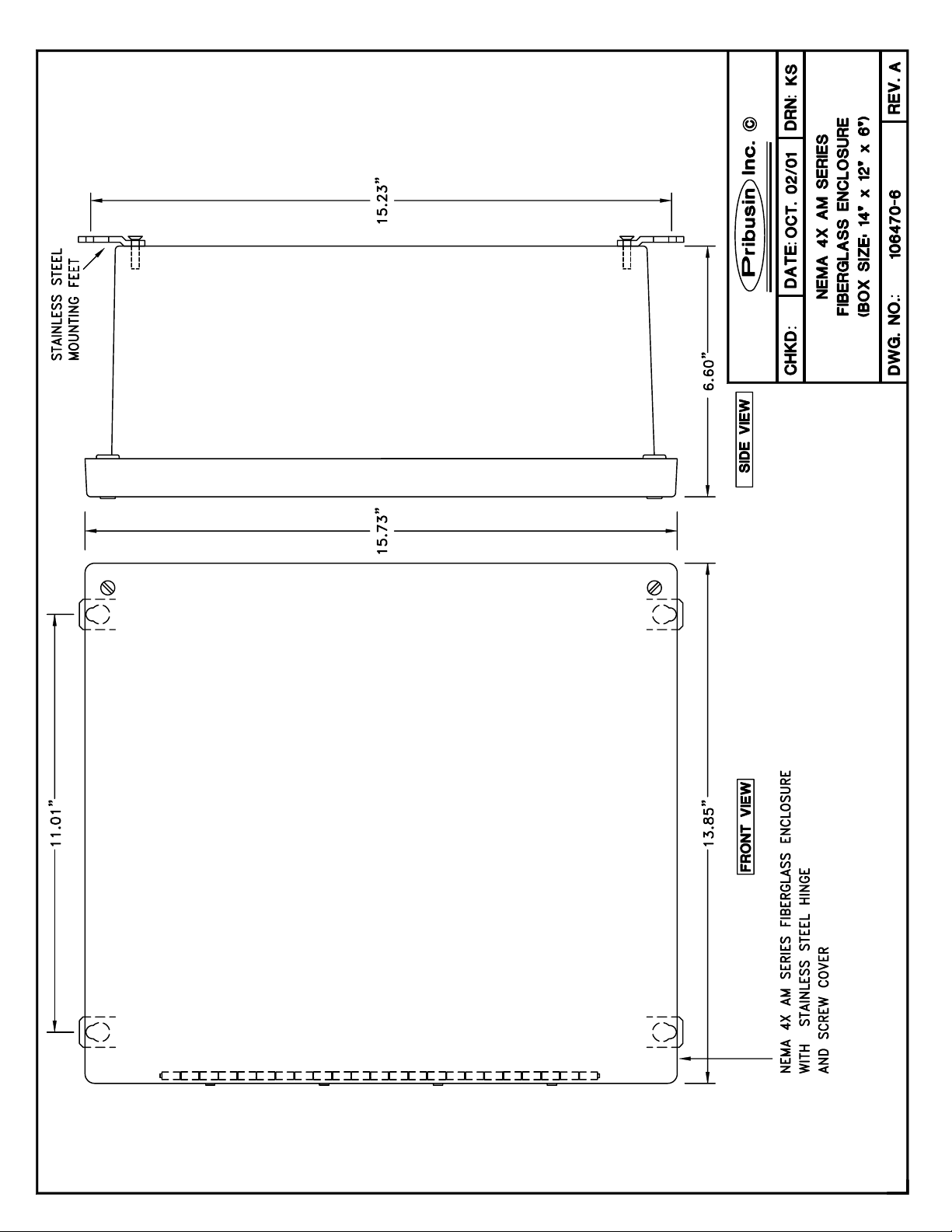


..\Manuals\RCI-400-FSK.doc Page 1 of 9
RCI-400 Connections:
The RCI-400 is the main board of an RCI-400-XXX Telemetry system. It provides the input and output
signal connections as well as the power supply for the unit. The RCI-400 consists of two circuit boards:
a main controller board with four contact inputs and four contact outputs and below it an analog
input/output board with four analog inputs and four analog outputs. A separate communications board
is added to the RCI-400 to allow it to communicate with other units. This communications board may
have its own configuration that is in a separate section of this manual. The following configuration
applies only to the RCI-400 board and is common to all communications interfaces.
AC Power & Fuse:
The RCI-400 is typically powered from 120VAC and protected by a 500mA
SLOBLO fuse. It can be wired for 240VAC operation by removing (de-
soldering) power jumpers J1 & J2 and installing (soldering) jumper J3.
When changing the RCI-400 to 240VAC power make sure to change the
fuse to half of its value, 250mA. This is important since at 240VAC the RCI-
400 requires only half the current as if it were powered from 120VAC.
Proper protection is only achieved by reducing the fuse value as mentioned
above.
DC Power & Battery Backup:
The RCI-400 may also be powered from a 24VDC source which could be a
battery or a DC power supply. The 24VDC power input is polarity protected
with a fuse to prevent damage to the RCI-400 by inadvertent reverse polarity.
A DC fuse provision is also provided if this power option is utilized. Insert a
5A automotive type blade fuse into the Battery Fuse socket.
A separate 1A fuse protects the 24VDC power output to field transmitters (+24V terminal on
analog inputs). This fuse is located on the analog input output board (bottom board).

..\Manuals\RCI-400-FSK.doc Page 2 of 9
Inputs:
The RCI-400 has four dry contact inputs and four 0-20mA inputs. The dry
contact inputs are excited with 24VDC and will source approximately 20mA
when the contact is closed. A red LED lights up when a contact input is closed.
The analog inputs are configured as 0-20mA inputs and have a 250Ωinput
impedance. Each input terminal has three connections: +24V, I/P, COM. The
+24V power output may be used to power field transmitters. Up to 125mA may
be used to power a transmitter. The input signal is connected to I/P(+) and
COM(-).
Analog inputs are connected to the RCI-400 in two fashions: 1) Normal (3-wire connection) or 2) two-
wire connection. On a 3-wire connected input, an external power supply or the +24V power output
terminal of the RCI provides power to the field transmitter. The field transmitter has a current source
that provides the 4-20mA signal back to the RCI-400. If using the power supply of the RCI-400, the
field transmitter may draw up to 125mA. A total of 1A is available to power up to 4 field transmitters.
On a 2-wire connected input, the field transmitter receives power from the RCI-400 and superimposes
the signal onto the power return path. A maximum of 20mA will flow in such a connection. Make sure
to consult the field transmitter manual to determine how to connect it to the RCI-400.
Outputs:
The RCI-400 has four form ‘C’ relay contact outputs and four 0-20mA analog outputs.
The relay contacts are capable of switching 120VAC, 10A or 240VAC, 6A. An energy
absorbing varistor is installed across each contact to limit switching transients. A
ninth relay contact acts as a communications fail indicator. If no communication
occurred within 60 seconds, this relay contact will energize. Upon re-established
communication this relay will de-energize again.
The four analog outputs are typically configured as 0-20mA outputs and
can drive into a 1000Ωload each, provided that the power supply to the
unit is not below 24VDC. The outputs are not isolated from each other
or from the inputs. Care must be taken when connecting the outputs to
different devices so that no inadvertent ground loops are established.

..\Manuals\RCI-400-FSK.doc Page 3 of 9
Output Calibration & Input Testing:
The outputs on the RCI-400 are factory calibrated and should not
require any adjustments. To check the calibration of the outputs and relays
use jumpers H1-7 & H1-8 as shown below to set them to known states. If an
output should require some adjustment, the main circuit board has to be
removed from the analog input/output board to gain access to the output
calibration potentiometers. With the power off, remove the main circuit
board and set it aside leaving it connected to the analog input/output board
via the 4-conductor I/O cable. Turn the power on and insert jumper H1-8 on
the main circuit board and turn the OUTPUT CALIB. trim pot for a particular
output until that output reads 20mA. Turn the power off again before re-
assembling the unit.
If both jumpers are IN the analog and contact inputs are passed straight through to the analog and
relay outputs. This may help in troubleshooting input and output signals.
Make sure both jumpers are removed before resuming normal operation.
H1-7 H1-8 Function
OUT OUT Normal Operation
OUT IN Outputs=20mA, Relays=Energized
IN OUT Outputs=0mA, Relays=De-energized
IN IN Outputs=Inputs, Relays=Contact Inputs

..\Manuals\RCI-400-FSK.doc Page 4 of 9
RCI-400 Configuration:
The RCI-400 requires no configuration other than for its communication fail operation. In the event of a
communications failure on the communications board, the RCI-400 can be set up to take various
actions on its outputs. This may be desirable in order to place connected devices into a safe operating
mode. By default factory setting, all outputs remain at their last known state if a communications failure
occurs.
1) If H1-3=IN then all analog outputs will ramp to the either 0% or 100% depending on jumper
H1-4. the outputs will change at a rate determined by the jumper H1-6.
2) The low end of the output value can be selected to be either 0mA or 4mA depending on
jumper H1-5. This setting only applies to the output value during a fail condition when the
outputs are selected to ramp to 0%. If jumper H1-5 is out, the outputs will ramp to 0mA, if it
is in they will ramp to 4mA. The setting of this jumper does not affect the outputs during
normal operation.
H1- Function OUT IN
1 Relay Fail Mode No Change See H1-2
2 Relay Fail Status De-Energize Energize
3 Output Fail Mode No Change See H1-4 1)
4 Output Fail Status Ramp to 0% Ramp to 100%
5 Output 0% Value
2) 0mA 4mA
6 Output Ramp Rate 10 seconds 60 seconds
7 I/O Calibration
8 I/O Calibration

..\Manuals\RCI-400-FSK.doc Page 5 of 9
FSK Communication Option:
The -FSK communications option for the RCI series utilizes Frequency Shift Keying modems on a
leased telephone line to exchange the signal data between a host and its remote(s). There are two
types of Topologies that can be configured: 1) Point-to-Point and 2) Host-to-Multipoint.
In a Point-to-Point topology one host
communicates with one remote. The
two exchange all their signals with one
another. The remote is configured as
remote #1 even though it is the only
remote in the system.
In a Host-to-Multipoint topology one
host communicates to several remotes.
Each remote is assigned an address
(1,2,3, etc.) so that the host may
distinguish between them. There may
at most be as many remotes as there
are inputs & outputs on the host.
There are two ways to physically
connect a Host-to-Multipoint system:
1) Bridging the remotes’ leased lines at
the phone company resulting in one
leased line being connected at the host
(preferred method). This eliminates
any impedance mismatch issues that
may arise by connecting two or more
phone lines in parallel.
2) Bridging the remotes’ leased lines at
the host. This can cause problems in
some cases because of impedance
mismatches in the two lines. It also
attenuates the FSK signal, which means
that a higher amplification setting on the
FSK board is necessary. If there is excess noise on the lines this would now also be amplified and may
interfere with the signal.

..\Manuals\RCI-400-FSK.doc Page 6 of 9
An RCI-400 configured as a host may communicate in one of the following system setups:
a) 1RCI-400 remote
b) 2RCI-200 remotes
c) 4RCI-200 remotes configured as 1-channel remotes
d) 4RCI-100 remotes
The above tables show the input-output relationships for the a), b), c) & d) system configurations
FSK Modem Configuration:
All FSK modem configurations are
done via two banks of DIPswitches.
SW1 assigns the remote address
from 1 to 200 using a binary
encoding scheme. SW2 assigns the
Topology, Channel Numbers and
Host/Remote Mode. The switches
are located on the communications
board just above the main circuit
board. They are a slanted rocker
type that flips up for OFF and down for ON.
The FSK communication board has two banks of 8-position DIPswitches: SW1 and SW2. The function
of these switches is slightly different for a host unit and a remote unit.
Host
(4-Channel)
Remote #1
(4-Channel)
DI 1-4 DO 1-4
DO 1-4 DI 1-4
AI 1-4 AO 1-4
AO 1-4 AI 1-4
Host
(4-Channel)
Remote #1
(1-Channel)
Remote #2
(1-Channel)
Remote #3
(1-Channel)
Remote #4
(1-Channel)
DI 1 DO 1
DI 1 DO 1
DI 3 DO 1
DI 4 DO 1
DO 1 DI 1
DO 2 DI 1
DO 3 DI 1
DO 4 DI 1
AI 1 AO 1
AI 2 AO 1
AI 3 AO 1
AI 4 AO 1
AO 1 AI 1
AO 2 AI 1
AO 3 AI 1
AO 4 AI 1
Host
(4-Channel)
Remote #1
(2-Channel)
Remote #2
(2-Channel)
DI 1-2 DO 1-2
DI 3-4 DO 1-2
DO 1-2 DI 1-2
DO 3-4 DI 1-2
AI 1-2 AO 1-2
AI 3-4 AO 1-2
AO 1-2 AI 1-2
AO 3-4 AI 1-2
SW1- HOST REMOTE
1 # of Remotes Remote Address
2 # of Remotes Remote Address
3 # of Remotes Remote Address
4 Remote Address
5 Remote Address
6 Remote Address
7 Remote Address
8 Remote Address
SW2- HOST REMOTE
1 # of Channels on each Remote # of Channels on this Remote
2 # of Channels on each Remote # of Channels on this Remote
3 # of Channels on Host
4 # of Channels on Host
5
6
7
8 Host / Remote Select Host / Remote Select

..\Manuals\RCI-400-FSK.doc Page 7 of 9
Host Configuration:
To make an RCI-400 operate as a host unit, make sure that SW2-8 is flipped down.
Next, set the number of remotes that the host is to
communicate with using SW1-1, -2, -3. These switches are
binary encoded as shown in the chart to the right.
Next, set the number of channels of each remote using SW2-1,
-2. One channel is considered 1 analog input/output plus 1
contact input/output. Hence an RCI-400 can have UP TO 4
channels. Remotes can only come in 1, 2 or 4 channel
configurations
Next, set the number of channels of the host using SW2-3, -4.
An RCI-400 can have 4 channels. This is the number of channels
that will be exchanged between the host and each remote. To
match the total number of channels on all remotes, select the
number of channels for the host.
Remote Configuration:
To make an RCI-400 operate as a REMOTE unit, make sure that SW2-8 is flipped up.
Next, set the remote address using SW1-1..8. This switch
is binary encoded and you will have to convert the remote
address to binary first. The table to the right lists the
beginning, most commonly used addresses. The table
extends to address 200 (using all 8 switches).
Next, set the number of channels on this remote using SW2-1,
-2. One channel is considered 1 analog input/output plus 1
contact input/output. Hence an RCI-400 can have up to 4
channels.
Receiver Gain Adjustment:
The FSK modem has a receive amplifier that can be used in various
stages of amplification to enhance communication. If the phone line
quality is poor or if the distance between units is great and presents
a large signal loss, increasing the receiver gain can be used to
amplify the incoming signal to restore reliable communication. Three
gain settings are available: +10dB, +20dB and +30dB. These are
selected via switch SW3. If all three switches are off, there is no
amplification.
SW1-1 SW1-2 SW1-3 # of Remotes
UP UP UP 1
DOWN UP UP 2
UP DOWN UP 3
DOWN DOWN UP 4
SW2-1 SW2-2 Channels on Remotes
UP UP 1
DOWN UP 2
UP DOWN 4
SW2-3 SW2-4 Channels on Host
UP UP 1
DOWN UP 2
UP DOWN 4
SW1-1 SW1-2 SW1-3 SW1-4 Address
UP UP UP UP 1
DOWN UP UP UP 2
UP DOWN UP UP 3
DOWN DOWN UP UP 4
UP UP DOWN UP 5
DOWN UP DOWN UP 6
UP DOWN DOWN UP 7
DOWN DOWN DOWN UP 8
SW2-1 SW2-2 Channels on Remote
UP UP 1
DOWN UP 2
UP DOWN 4

..\Manuals\RCI-400-FSK.doc Page 8 of 9
Use the lowest amplification setting that yields good results since too high of an amplification setting
can distort the signal yielding unreliable communication also. To judge the state of your
communication, use the red and green Transmit and Receive LEDs.
On a host unit, the red Transmit LED will light first for a fraction of a second. This
is an interrogation message sent to the remote. If the remote received the
message entirely and correctly, it will reply with a return message, which causes
the host’s green Receive LED to light for a fraction of a second. This is followed
by the host then sending out the next message and so on.
In other words, every Transmit LED flash should be followed by a Receive LED
flash. If a Transmit LED flash is NOT followed by a Receive LED flash this means
that one of the remotes did not receive its interrogation message properly or is
currently not powered. By changing the receiver gain setting try to achieve a continuous
Transmit/Receive LED flash pattern.
Occasional transmission misses are of no real concern since the units wait for 1 minute during a
continuous communication loss before signaling a loss of communication. During this 1-minute delay
all outputs are held at their last known value.
On a remote unit, the order of the LED flashes is reversed since the remote waits for an interrogation
message from the host before it replies. The Receive LED will flash first followed by a flash of the
Transmit LED.
A complete data exchange requires 4 transmissions between the host and a remote. This becomes
important when considering a Host-to-Multipoint system. On the host the LED flash sequence remains
unchanged. On the remote units, however, the Receive LED will flash every time any message is sent
on the phone line. This includes messages not intended for a given remote. For example, if the host is
currently communicating with remote #1, the Receive LED on remote #2 will flash for every
interrogation and reply message that are exchanged between the host and remote #1. Only when the
host begins to communicate with remote #2 does the normal Receive/Transmit flash sequence occur.

..\Manuals\RCI-400-FSK.doc Page 9 of 9
Leased Line Connection & Specifications:
The RCI-XXX-FSK uses a leased line to communicate. A leased line is a regular telephone line without
the dial tone. It is essentially always ON. If you were to connect a telephone at either end and two
people were to pick up the receiver they could just start talking.
The leased line must be specially installed by the telephone company and they may have various
services available. The RCI-XXX-FSK does not require a special type of service (such as data, full-
duplex, etc.). All that is required is a 2-wire, un-powered, voice-grade line without dial tone.
The leased line is then connected to the FSK modem
using a standard RJ-11 modular connector with the
center two pins being the Tip and Ring wires (typically
red & green). Two fuses are provided for protection of
the FSK modem. They are a 1/4A fast-blo 5x20mm
type.
We strongly suggest installing additional surge and
lightning protection at the point where the leased line enters the building. The protection on the
FSK modem board is not sufficient to protect against lightning strikes or large power surges.
Table of contents
Other Pribusin Recording Equipment manuals