Pribusin RCI-800 Series User manual

Manufacturers of Process
Controls and Instrumentation
Instruction Manual
Model:
Serial #:
Power:
Function:
XXX=MDM Modem Dial-Up
Communication:
RCI-800-XXX
(If special or required)
24 VDC
8 “Dry” Contacts and 8 Analog Inputs
Input:
Remote Control Signal Interface
XXX=SER: RS-232/485
Output: 8 Form ‘C’ Contacts and 8 Analog Outputs
117VAC, 50/60Hz
XXX=RF9: 900 Mhz Wireless
XXX=FSK: Leased Line
XXX=R : 2.4 Ghz WirelessF2
For Technical Assistance And Questions Call
USA: (231) 788-2900 CANADA: (905) 660-5336

Restocking Policy
Page v
Warranty Policy
All product returned to Pribusin Inc. in prime condition (not
damaged, scratched or defaced in any way) within seven (7)
months from the original date of shipment is subject to a 50%
restocking charge. All product must be accompanied by a
Return Authorization number (RA number) which must be
obtained from Pribusin Inc. prior to returning any product.
After seven (7) months from the original date of shipment,
products cannot be returned for restocking.
Custom designed products, modified products or all non-
standard products may not be returned for restocking.
Pribusin Inc. warrants equipment of its own manufacture to be
free from defects in material and workmanship, under normal
conditions of use and service, and will replace any component
found to be defective, on its return to Pribusin Inc.,
transportation charges prepaid, within one year of its original
purchase. Pribusin Inc. will extend the same warranty
protection on equipment, peripherals and accessories which is
extended to Pribusin Inc. by the original manufacturer. Pribusin
Inc. also assumes noliability, expressed or implied, beyond its
obligation to prelace any component involved. Such warranty
is in lieu of all other warranties, expressed or implied.

Function:
The RCI-800-RF2 is a bi-directional data communication
system that exchanges the status of 8 dry contact inputs
and 8 analog inputs between a master and one or more
remote units. A basic system consists of one master
station and one remote station each with 8 dry contact
and 8 analog inputs and 8 'C' relay contact and analog
outputs. All signals are bi-directional so that data may be
read from the remote station and sent to it.
The license-free spread-spectrum radio technology
allows small systems to be set up with very little effort and
at low cost. The technology ensures high
communication reliability even in RF-intensive
environments.
All units are sold with a ¼ wave omnidirectional whip
antenna. Other antennas, such as directional Yagi or
Patch antennas, are sold separately.
Options:
-A: 24VDC Power
- B: 240VAC Power
- N12: NEMA12 Enclosure
Standard Features:
Bi-directional Communication using License-free
2.4GHz Radio Band
Spread-Spectrum Radio Technology Provides
Reliable Communication
Re-Transmission & Error Correction Algorithms
ensure Accurate Data Transmission
8 Dry Contact and 8 Analog Inputs
8 'C' Relay Contacts and 8 Analog Outputs
Point-to-Point or Host-to-Multipoint Topologies
No Calibration Required
Microprocessor Controlled for High Accuracy
Power: 117 VAC 50/60 Hz (Optional 24 VDC)
High Noise Rejection
CSA and NRTL Approved (LR51078)
Specifications:
Media: 2.4GHz Spread-Spectrum Radio
Range: up to 1500ft indoors with omnidirectional antenna
up to 12 miles line-of-sight with directional antenna
Protocol: MODBUS ASCII
Speed: 9600 BAUD
Radio Power Output: 500mW max.
Operating Temperature: -4°F to +140°F (-20°C to +60°C)
Relay Contacts: 10A 1/8Hp @ 125VAC
6A 1/8Hp @ 277VAC
Power: 117 VAC, 60/50 Hz, 24VDC Available
Enclosure: NEMA4X (NEMA12 available as an option)
Approvals: ETL 3118354:
UL 60950-1-2007; CSA-C22.2 No. 60950-1-07
Model: RCI-800-RF2
Remote Control Signal Interface
With 2.4GHZ Radio Frequency Link
Page J12
Manufacturers of Process
Controls and Instrumentation
- R: Remote Radio
(Radio is in separate
enclosure and mounts
close to antenna to
prevent signal loss for
long cable runs)
3118354

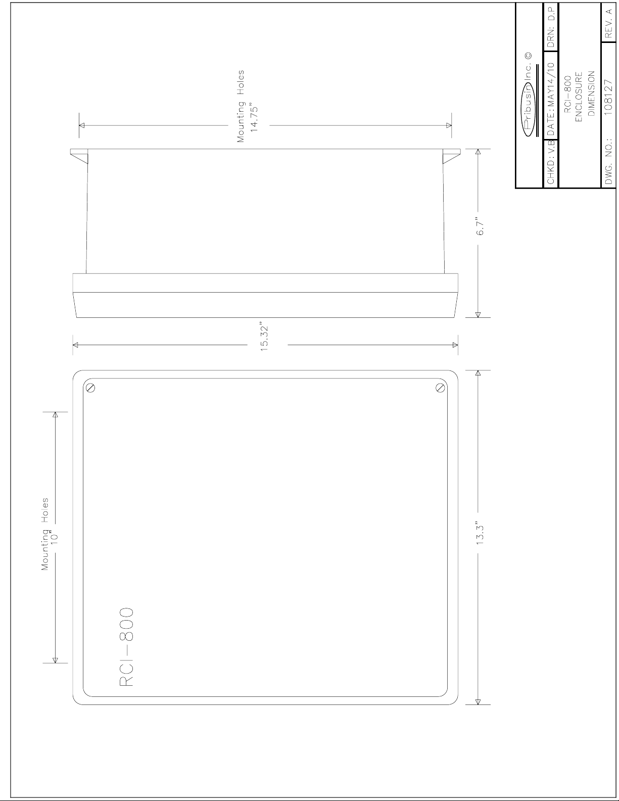
Enclosures & Dimensions:
Connection:
RCI-800-RF2
System A
System B
Manufactured By:
8 Analog
8 Contact
8 Analog
8 Contact
8 Analog
8 Contact 8 Analog
8 Contact
Option -R
8 Analog
8 Contact 8 Analog
8 Contact
Radio
Serial Link
Point-to-Point
8 Analog
8 Contact 8 Analog
8 Contact
OR
Master
Remote 1
8 Analog
8 Contact
8 Analog
8 Contact
Remote 2
Remote 3
Master to Multi-Remote
8 Analog
8 Contact
8 Analog
8 Contact 8 Analog
8 Contact
8 Analog
8 Contact
Page J12
(any system)
15.25”
13.25” 6.5”
www.pribusin.com
CANADA:
Pribusin Inc.
101 Freshway Dr. Unit 57
Concord, Ontario, L4K 1R9
Ph: (905) 660-5336
Fx: (905) 660-4068
USA:
Pribusin Inc.
743 Marquette Ave.
Muskegon, MI 49442
Ph: (231) 788-2900
Fx: (231) 788-2929
Rev.B Subject to change without notice
..\Manuals\RCI-800-RF2 rev.D.doc Page 1 of 16
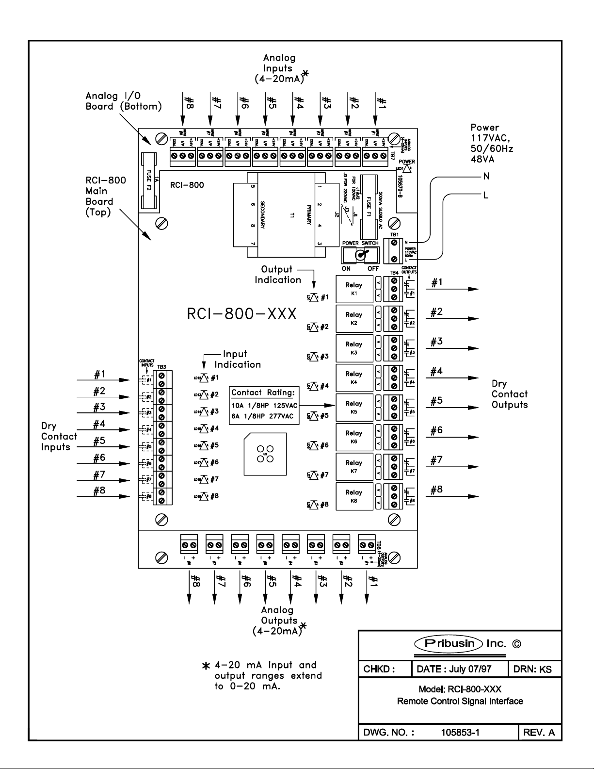
RCI-800 Connections:
The RCI-800 is the main board of an RCI-800-XXX Telemetry system. It provides the input and output
signal connections as well as the power supply for the unit. The RCI-800 consists of two circuit boards:
a main controller board with eight contact inputs and eight contact outputs and below it an analog
input/output board with eight analog inputs and eight analog outputs. A separate communications
board is added to the RCI-800 to allow it to communicate with other units. This communications board
may have its own configuration that is in a separate section of this manual. The following configuration
applies only to the RCI-800 board and is common to all communications interfaces.
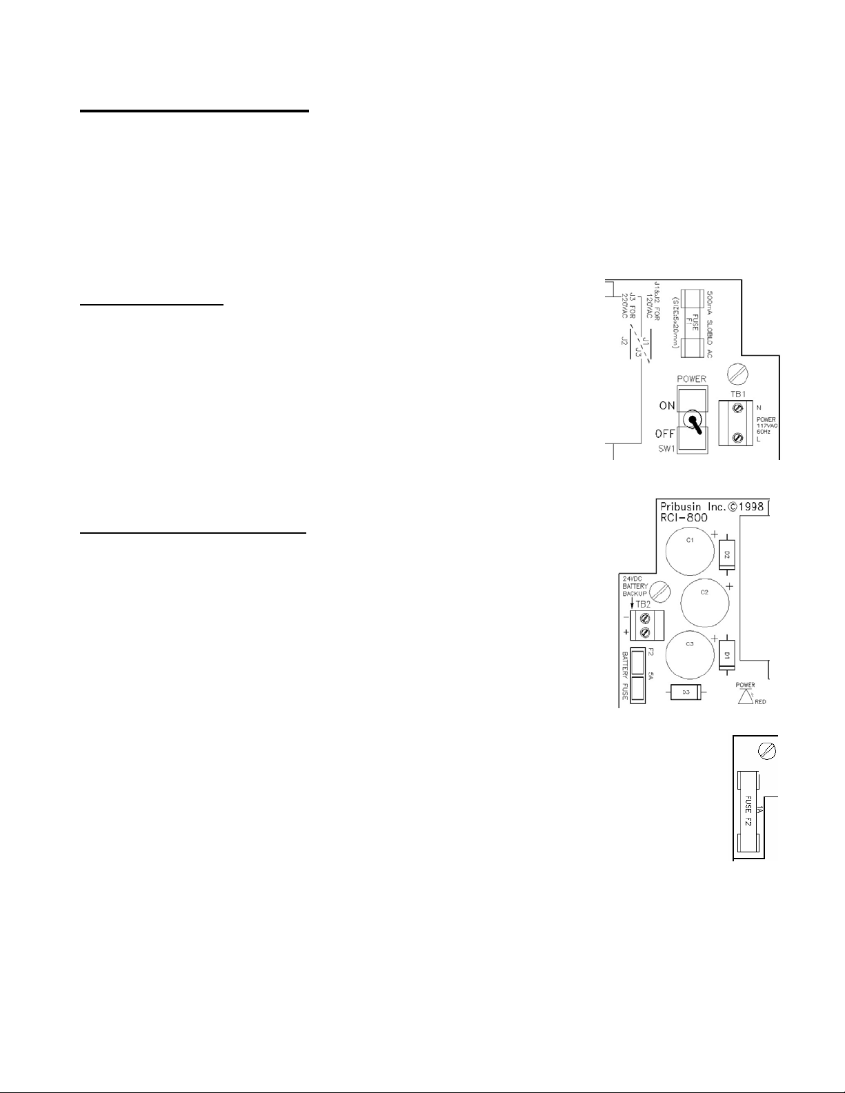
AC Power & Fuse:
The RCI-800 is typically powered from 120VAC and protected by a 500mA
SLOBLO fuse. It can be wired for 240VAC operation by removing (de-
soldering) power jumpers J1 & J2 and installing (soldering) jumper J3.
When changing the RCI-800 to 240VAC power make sure to change the
fuse to half of its value, 250mA. This is important since at 240VAC the RCI-
800 requires only half the current as if it were powered from 120VAC.
Proper protection is only achieved by reducing the fuse value as mentioned
above.
DC Power & Battery Backup:
The RCI-800 may also be powered from a 24VDC source which could be a
battery or a DC power supply. The 24VDC power input is polarity protected
with a fuse to prevent damage to the RCI-800 by inadvertent reverse polarity.
A DC fuse provision is also provided if this power option is utilized. Insert a
5A automotive type blade fuse into the Battery Fuse socket.
A separate 1A fuse protects the 24VDC power output to field transmitters (+24V terminal on
analog inputs). This fuse is located on the analog input output board (bottom board).

..\Manuals\RCI-800-RF2 rev.D.doc Page 2 of 16
Inputs:
The RCI-800 has eight dry contact inputs and eight 0-20mA inputs. The dry
contact inputs are excited with 24VDC and will source approximately 20mA
when the contact is closed. A red LED lights up when a contact input is closed.
The analog inputs are configured as 0-20mA inputs and have a 250Ωinput
impedance. Each input terminal has three connections: +24V, I/P, COM. The
+24V power output may be used to power field transmitters. Up to 125mA may
be used to power a transmitter. The input signal is connected to I/P(+) and
COM(-).
Analog inputs are connected to the RCI-800 in two fashions: 1) Normal (3-wire connection) or 2) two-
wire connection. On a 3-wire connected input, an external power supply or the +24V power output
terminal of the RCI provides power to the field transmitter. The field transmitter has a current source
that provides the 4-20mA signal back to the RCI-800. If using the power supply of the RCI-800, the
field transmitter may draw up to 125mA. A total of 1A is available to power up to 8 field transmitters.
On a 2-wire connected input, the field transmitter receives power from the RCI-800 and superimposes
the signal onto the power return path. A maximum of 20mA will flow in such a connection. Make sure
to consult the field transmitter manual to determine how to connect it to the RCI-800.
Outputs:
The RCI-800 has eight form ‘C’ relay contact outputs and eight 0-20mA analog
outputs. The relay contacts are capable of switching 120VAC, 10A or 240VAC, 6A.
An energy absorbing varistor is installed across each contact to limit switching
transients. A ninth relay contact acts as a communications fail indicator. If no
communication occurred within 60 seconds, this relay contact will energize. Upon re-
established communication this relay will de-energize again.
The eight analog outputs are typically configured as 0-20mA outputs and
can drive into a 1000Ωload each, provided that the power supply to the
unit is not below 24VDC. The outputs are not isolated from each other
or from the inputs. Care must be taken when connecting the outputs to
different devices so that no inadvertent ground loops are established.
..\Manuals\RCI-800-RF2 rev.D.doc Page 3 of 16
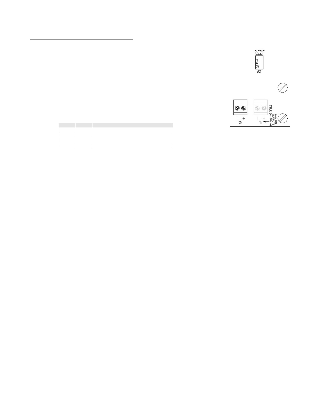
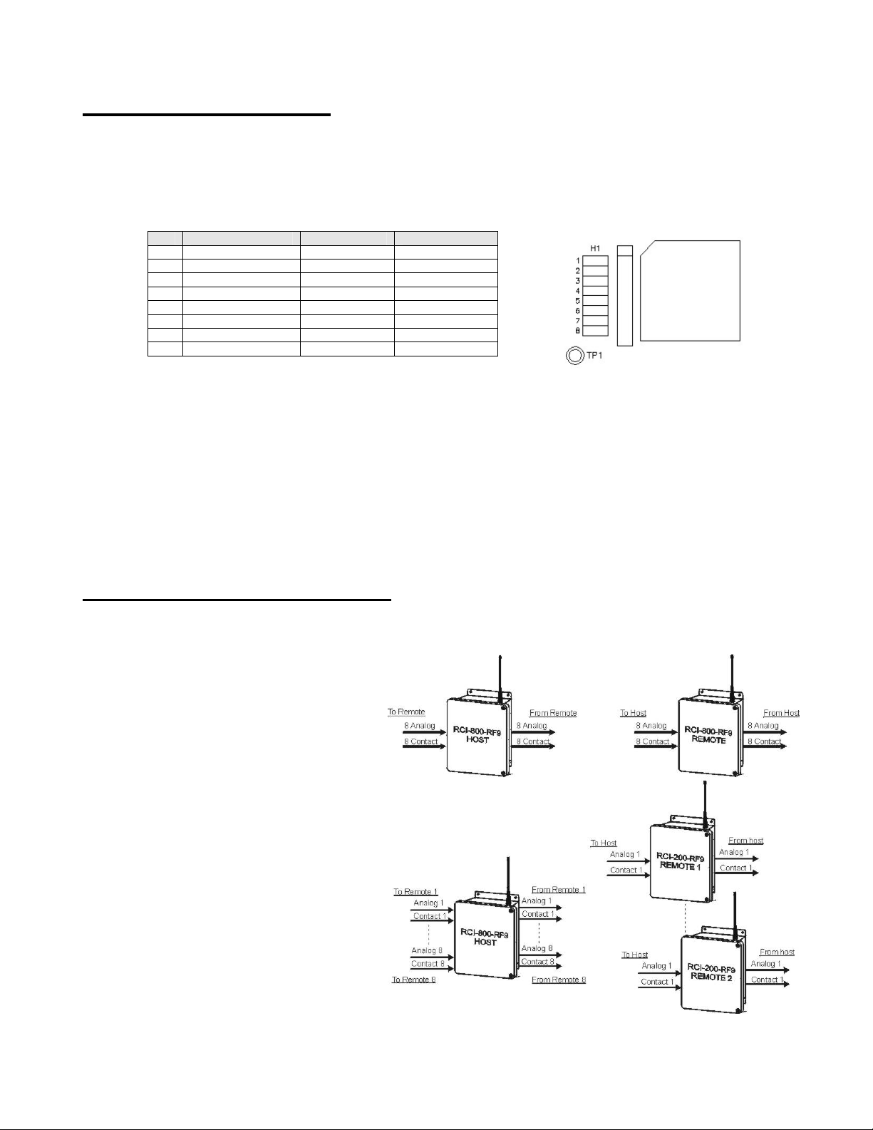
Output Calibration & Input Testing:
The outputs on the RCI-800 are factory calibrated and should not
require any adjustments. To check the calibration of the outputs and relays
use jumpers H1-7 & H1-8 as shown below to set them to known states. If an
output should require some adjustment, the main circuit board has to be
removed from the analog input/output board to gain access to the output
calibration potentiometers. With the power off, remove the main circuit
board and set it aside leaving it connected to the analog input/output board
via the 4-conductor I/O cable. Turn the power on and insert jumper H1-8 on
the main circuit board and turn the OUTPUT CALIB. trim pot for a particular
output until that output reads 20mA. Turn the power off again before re-
assembling the unit.
If both jumpers are IN the analog and contact inputs are passed straight through to the analog and
relay outputs. This may help in troubleshooting input and output signals.
Make sure both jumpers are removed before resuming normal operation.
H1-7 H1-8 Function
OUT OUT Normal Operation
OUT IN Outputs=20mA, Relays=Energized
IN OUT Outputs=0mA, Relays=De-energized
IN IN Outputs=Inputs, Relays=Contact Inputs
..\Manuals\RCI-800-RF2 rev.D.doc Page 4 of 16
RCI-800 Configuration:
The RCI-800 requires no configuration other than for its communication fail operation. In the event of a
communications failure on the communications board, the RCI-800 can be set up to take various
actions on its outputs. This may be desirable in order to place connected devices into a safe operating
mode. By default factory setting, all outputs remain at their last known state if a communications failure
occurs.
1) If H1-3=IN then all analog outputs will ramp to the either 0% or 100% depending on jumper
H1-4. The outputs will change at a rate determined by the jumper H1-6.
2) The low end of the output value can be selected to be either 0mA or 4ma depending on
jumper H1-5. This setting only applies to the output value during a fail condition when the
outputs are selected to ramp to 0%. If jumper H1-5 is out, the outputs will ramp to 0mA, if it
is in they will ramp to 4mA. The setting of this jumper does not affect the outputs during
normal operation.
RF2 Communication Option:
The –RF2 communications option to the RCI series utilizes license-free spread spectrum radio
frequency transmissions to exchange the
signal data between a host and its
remote(s). There are two types of
Topologies that can be configured: 1)
Point-to-Point and 2) Host-to-Multipoint.
In a Point-to-Point topology one host
communicates with one remote. The two
exchange all their signals with one
another. The remote is configured as
remote #1 even though it is the only
remote in the system.
In a Point-to-Multipoint topology one
host communicates to several remotes.
Each remote is assigned an address
(1,2,3, etc.) so that the host may
distinguish between them. There may at
most be as many remotes as there are
inputs & outputs on the host.
H1- Function OUT IN
1 Relay Fail Mode No Change See H1-2
2 Relay Fail Status De-Energize Energize
3 Output Fail Mode No Change See H1-4 1)
4 Output Fail Status Ramp to 0% Ramp to 100%
5 Output 0% Value 2) 0mA 4mA
6 Output Ramp Rate 10 seconds 60 seconds
7 I/O Calibration
8 I/O Calibration

..\Manuals\RCI-800-RF2 rev.D.doc Page 5 of 16
An RCI-800 configured as a host may communicate in one of the following system setups:
a) 1RCI-800 remote
b) 2RCI-800 remotes configured as 4-channel remotes
c) 4RCI-200 remotes each having 2 channels
d) 8RCI-200 remotes configured as 1-channel remotes
The above tables show the input-output relationships for the a), b) & c) system configurations. For
space reasons the table for system d) was omitted but can easily be deduced from the system c) table.
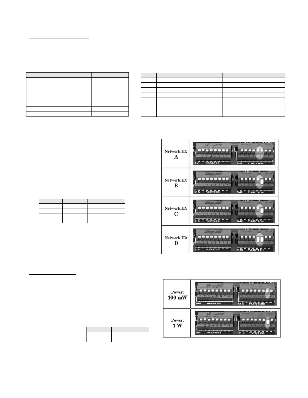
A Network ID allows multiple RF2 systems to co-exist within close proximity without interfering with
one another. There are four Network ID’s to choose from: A, B, C or D. The host and its remote(s)
must be set to the same Network ID in order for them to communicate with each other.
All radio configurations are
done via two banks of DIP
switches. SW1 assigns the
remote address from 1 to
100 using a binary encoding
scheme. SW2 assigns the
Topology, Network ID,
Channel Numbers and
Host/Remote Mode. The
switches are located on the
communications board just below the radio. They are a slanted rocker type that flips up for OFF and
down for ON.
Host
(8-Channel) Remote #1
(8-Channel)
DI 1-8 DO 1-8
DO 1-8 DI 1-8
AI 1-8 AO 1-8
AO 1-8 AI 1-8
Host
(8-Channel) Remote #1
(2-Channel) Remote #2
(2-Channel) Remote #3
(2-Channel) Remote #4
(2-Channel)
DI 1-2 DO 1-2
DI 3-4 DO 1-2
DI 5-6 DO 1-2
DI 7-8 DO 1-2
DO 1-2 DI 1-2
DO 3-4 DI 1-2
DO 5-6 DI 1-2
DO 7-8 DI 1-2
AI 1-2 AO 1-2
AI 3-4 AO 1-2
AI 5-6 AO 1-2
AI 7-8 AO 1-2
AO 1-2 AI 1-2
AO 3-4 AI 1-2
AO 5-6 AI 1-2
AO 7-8 AI 1-2
Host
(8-Channel) Remote #1
(4-Channel) Remote #2
(4-Channel)
DI 1-4 DO 1-4
DI 5-6 DO 1-4
DO 1-4 DI 1-4
DO 5-6 DI 1-4
AI 1-4 AO 1-4
AI 5-6 AO 1-4
AO 1-4 AI 1-4
AO 5-6 AI 1-4
..\Manuals\RCI-800-RF2 rev.D.doc Page 6 of 16
Radio Configuration:
The radio communication board has two banks of 8-position DIPswitches: SW1 and SW2. The function
of these switches is slightly different for a host unit and a remote unit. We recommend powering the
unit down while making any changes to the configuration.
Network ID:
The Network ID is common to both the
host and remote modes of operation. All
hosts and remotes that are intended to
communicate with each other must be set
to the same Network ID. Four ID’s are
available: A, B, C, D. They are set as
shown in the table.
SW2-5 SW2-6 Network ID
UP UP A
DOWN UP B
UP DOWN C
DOWN DOWN D
SW2- HOST REMOTE
1 # of Channels on each Remote # of Channels on this Remote
2 # of Channels on each Remote # of Channels on this Remote
3 # of Channels on Host SHP
4 # of Channels on Host SHP
5 Network ID Network ID
6 Network ID Network ID
7 RF Output Power RF Output Power
8 Host / Remote Select Host / Remote Select
SW1- HOST REMOTE
1 # of Remotes Remote Address
2 # of Remotes Remote Address
3 # of Remotes Remote Address
4 Communication Timing PHP
5 Communication Timing PHP
6 PHP
7 Repeater Select
8 RF Speed RF Speed
RF Output Power:
The radio output power can be selected with
SW2-7. For shorter transmission ranges select
the 100mW range to limit the amount of ‘RF
pollution’. Select the 1W setting for: a) longer
transmission ranges, b) heavy foliage
transmission scenarios, c) if there is no
communication at the 100mW setting, or d) if the
signal strength is less
than -93dBm. SW2-7 RF Power
UP 100 mW
DOWN 1 W
..\Manuals\RCI-800-RF2 rev.D.doc Page 7 of 16
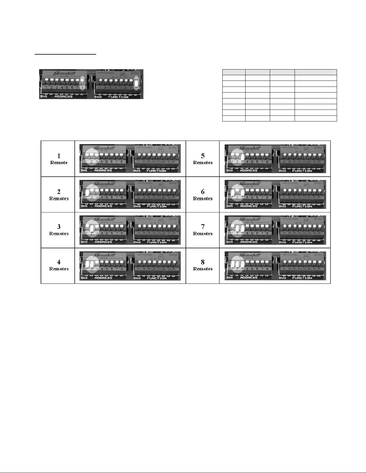
Host Configuration:
To make an RCI-800
operate as a host unit,
make sure that SW2-8
is flipped down.
Next, set the number of remotes that the host is to
communicate with using SW1-1, -2, -3. These switches are
binary encoded as shown in the chart to the right.
SW1-1 SW1-2 SW1-3 # of Remotes
UP UP UP 1
DOWN UP UP 2
UP DOWN UP 3
DOWN DOWN UP 4
UP UP DOWN 5
DOWN UP DOWN 6
UP DOWN DOWN 7
DOWN DOWN DOWN 8
..\Manuals\RCI-800-RF2 rev.D.doc Page 8 of 16
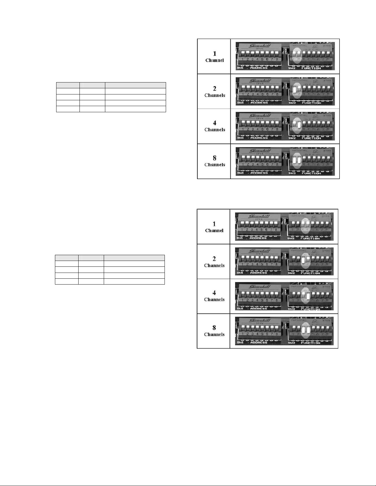
Next, set the number of channels of each
remote using SW2-1, -2. One channel is
considered 1 analog input/output plus 1 contact
input/output. Hence an RCI-800 can have at most
8 channels.
SW2-1 SW2-2 Channels on Remotes
UP UP 1
DOWN UP 2
UP DOWN 4
DOWN DOWN 8
Next, set the number of channels of the host
using SW2-3, -4. An RCI-800 can at most have 8
channels. This is the number of channels that
will be exchanged between the host and each
remote.
SW2-3 SW2-4 Channels on Host
UP UP 1
DOWN UP 2
UP DOWN 4
DOWN DOWN 8

..\Manuals\RCI-800-RF2 rev.D.doc Page 9 of 16
Optional (for repeater networks)
If you are using a repeater in your network or if the
RCI system is located in a heavy interference
area, you may need to adjust the communication
timing. Since the radios have built in error
correction algorithms to insure reliable and error
free communication this can sometimes cause the
communication to slow down by a few 10ths of a
second. To compensate for this slow-down, the
communication timing gives the data packets
returning from the remote additional time to reach
the host.
SW1-4 SW1-5 Communication Timing
(seconds)
UP UP Full Speed
DOWN UP 0.2sec delay
UP DOWN 0.4sec delay
DOWN DOWN 0.6sec delay
Remote Configuration:
To make an RCI-800
operate as a REMOTE
unit, make sure that
SW2-8 is flipped up.
Next, set the remote address using SW1-1, -2 & -3. Each
remote in a system must have a unique address.
SW1-1 SW1-2 SW1-3 Remote Address
UP UP UP 1
DOWN UP UP 2
UP DOWN UP 3
DOWN DOWN UP 4
UP UP DOWN 5
DOWN UP DOWN 6
UP DOWN DOWN 7
DOWN DOWN DOWN 8

..\Manuals\RCI-800-RF2 rev.D.doc Page 10 of 16
Next, set the number of channels on this remote
using SW2-1, -2. One channel is considered 1
analog input/output plus 1 contact input/output.
Hence an RCI-800 can have at most 8 channels.
SW2-1 SW2-2 Channels on Remotes
UP UP 1
DOWN UP 2
UP DOWN 4
DOWN DOWN 8
Perform the next step only if this remote is
communicating to the host via a repeater!!!
Next, set the remote PHP using SW1-4, -5, -6.
The PHP of the repeater must match the SHP
of the unit before it. If this is a host than set the
repeater PHP=1.
SW1-4 SW1-5 SW1-6 Remote PHP
UP UP UP 1
DOWN UP UP 2
UP DOWN UP 3
DOWN DOWN UP 4
UP UP DOWN 5
DOWN UP DOWN 6
UP DOWN DOWN 7
DOWN DOWN DOWN 8

..\Manuals\RCI-800-RF2 rev.D.doc Page 11 of 16
Remote with Repeater (optional)
To make an RCI-800- Operate as a remote-
repeater unit, make sure that SW1-8 is flipped
down and SW2-8 is flipped up.
In this mode, the unit will function like any other
remote. In addition, the unit will be able to send
data to remotes whose PHP is set to the same as
the remote-repeater’s SHP.
To set the Secondary Hop Patter (SHP) for a
remote-repeater, use switches SW2-3, -4. The
SHP on a remote/repeater starts at 2. The
Primary Hop Pattern (PHP) of remotes that
communicate via this remote/repeater must
match this SHP.
SW2-3 SW2-4 SHP
UP UP 2
DOWN UP 3
UP DOWN 4
DOWN DOWN 5

..\Manuals\RCI-800-RF2 rev.D.doc Page 12 of 16
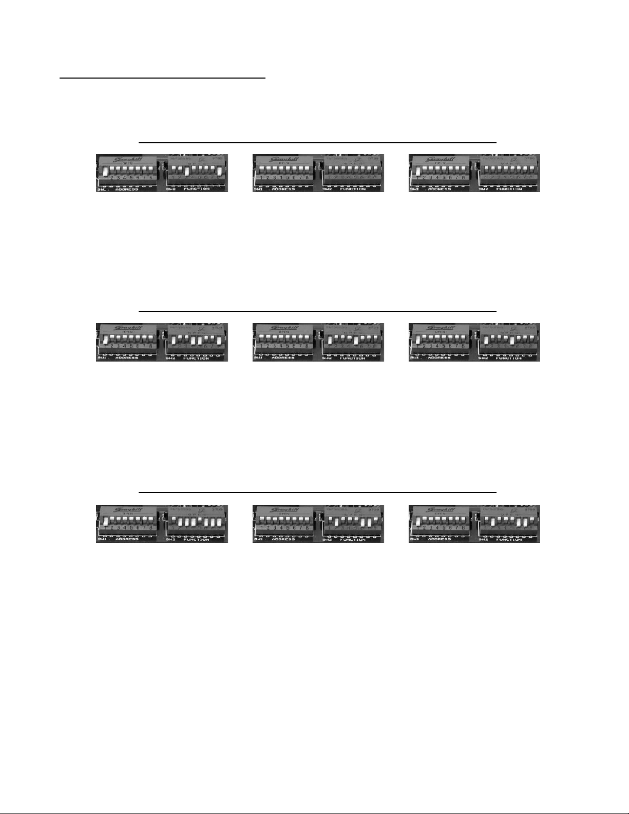
Point-to-Point Communication
Communication between one host and one remote is called point-to-point.
Example 1: An RCI-100 Host communicating with an RCI-100 Remote
Example 2: An RCI-200 Host communicating with an RCI-200 Remote
RCI-200 (Host) RCI-200 (Remote)
Host Channels: 2Remote Channels: 2
Number of Remotes: 1Network ID: AAddress: 1Network ID: A
Channels on Remotes: 2Power: 100mW Power: 100mW
Example 3: An RCI-400 Host communicating with an RCI-400 Remote
RCI-400 (Host) RCI-400 (Remote)
Host Channels: 4Remote Channels: 4
Number of Remotes: 1Network ID: AAddress: 1Network ID: A
Channels on Remotes: 4Power: 100mW Power: 100mW
Example 4: An RCI-800 Host communicating with an RCI-800 Remote
RCI-800 (Host) RCI-800 (Remote)
Host Channels: 8Remote Channels: 8
Number of Remotes: 1Network ID: AAddress: 1Network ID: A
Channels on Remotes: 8Power: 100mW Power: 100mW
RCI-100 (Host) RCI-100 (Remote)
Host Channels: 1Remote Channels: 1
Number of Remotes: 1Network ID: AAddress: 1Network ID: A
Channels on Remotes: 1Power: 100mW Power: 100mW
..\Manuals\RCI-800-RF2 rev.D.doc Page 13 of 16
Point-to-Multipoint Communication
Communication between a host and more than one remote is called point-to-multipoint.
Example 1: An RCI-200 Host communicating with (2) RCI-100 Remotes
Example 2: An RCI-400 Host communicating with (2) RCI-200 Remotes
Example 3: An RCI-800 Host communicating with (2) RCI-400 Remotes
RCI-200 (Host) RCI-100 (Remote 1) RCI-100 (Remote 2)
Host Channels: 2
Number of Remotes: 2
Channels on Remotes: 1
Network ID: A
Power: 100mW
Remote Channels: 1
Address: 1
Network ID: A
Power: 100mW
Remote Channels: 1
Address: 2
Network ID: A
Power: 100mW
RCI-400 (Host) RCI-200 (Remote 1) RCI-200 (Remote 2)
Host Channels: 4
Number of Remotes: 2
Channels on Remotes: 2
Network ID: B
Power: 100mW
Remote Channels: 2
Address: 1
Network ID: B
Power: 100mW
Remote Channels: 2
Address: 2
Network ID: B
Power: 100mW
RCI-800 (Host) RCI-400 (Remote 1) RCI-400 (Remote 2)
Host Channels: 8
Number of Remotes: 2
Channels on Remotes: 4
Network ID: C
Power: 1W
Remote Channels: 4
Address: 1
Network ID: C
Power: 1W
Remote Channels: 4
Address: 2
Network ID: C
Power: 1W

..\Manuals\RCI-800-RF2 rev.D.doc Page 14 of 16
Example 4: An RCI-800 Host communicating with (3) RCI-200 Remotes
Example 5: An RCI-400 Host communicating with (3) RCI-100 Remotes via Repeater
RCI-800 (Host)
Host Channels: 8
Number of Remotes: 3
Channels on Remotes: 2
Network ID: A
Power: 100mW
RCI-200 (Remote 1) RCI-200 (Remote 2) RCI-200 (Remote 3)
Remote Channels: 2
Address: 1
Network ID: A
Power: 100mW
Remote Channels: 2
Address: 2
Network ID: A
Power: 100mW
Remote Channels: 2
Address: 3
Network ID: A
Power: 100mW
RCI-100 (Remote 1) RCI-100 (Remote 2) RCI-100 (Remote 3)
Remote Channels: 1
Address: 1
Network ID: A
Power: 1W
Remote Channels: 1
Address: 2
Network ID: A
Power: 1W
Remote Channels: 1
Address: 3
Network ID: A
Power: 1W
RCI-400 (Host) RCI-RPT (Repeater)
Host Channels: 4
Number of Remotes: 3
Channels on Remotes: 1
Network ID: A
Power: 1W
Repeater Select: YES
Network ID: A
Power: 1W
This manual suits for next models
1
Table of contents
Other Pribusin Recording Equipment manuals


