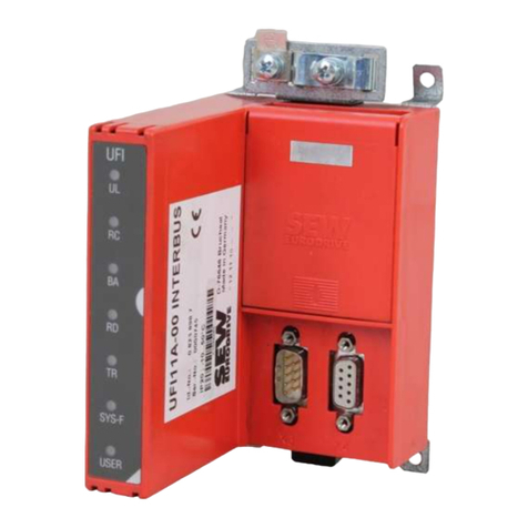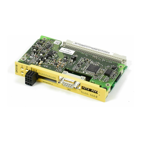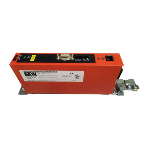
Manual – MOVIDRIVE® MDX61B INTERBUS DFI11B Fieldbus Interface
5
2
Introduction
2 Introduction
Contents of this
manual
This user manual describes how to install the INTERBUS DFI11B option card in the
MOVIDRIVE®MDX61B drive inverter and how to start up MOVIDRIVE®with the
INTERBUS fieldbus system.
It also contains an explanation of all settings on the fieldbus option card and connection
variants with INTERBUS in the form of small startup examples.
Additional
documentation
For a simple and effective connection of MOVIDRIVE®to the INTERBUS fieldbus
system, you should request the following publications from SEW-EURODRIVE about
the fieldbus technology in addition to this manual:
•MOVIDRIVE
®Fieldbus Unit Profile manual
•MOVIDRIVE
®MDX60/61B system manual
The manual for the MOVIDRIVE®fieldbus unit profile describes the fieldbus parameters
and their coding. It also explains the whole range of control concepts and application
options in the form of small examples.
The parameter list is a list of all drive inverter parameters that can be read and written
via various communication interfaces such as RS-485, SBus and even the fieldbus
interface.
MOVIDRIVE®and
INTERBUS
The MOVIDRIVE®drive inverter together with the DFI11B option and its high-
performance universal fieldbus interface enable the connection to master
programmable controllers via the open and standardized INTERBUS fieldbus system.
Unit profile
The performance of the inverter (also referred to as the unit profile) that forms the basis
for INTERBUS operation, is fieldbus-independent and, therefore, uniform. This allows
the user to develop fieldbus-independent drive applications. This makes it much easier
to change to other bus systems, such as PROFIBUS (DFP 21B option) or DeviceNet
(DFD 21B option).
Drive parameters
MOVIDRIVE®offers digital access to all drive parameters and functions via the
INTERBUS interface. The drive inverter is controlled via the fast, cyclical process data.
This process data channel offers the opportunity to initiate various drive functions such
as enable, controller inhibit, normal stop, rapid stop, and to specify setpoint values such
as setpoint speed, integrator time for acceleration/ramp down.
At the same time you can also use this channel to read back actual values from the drive
inverter, such as actual speed, current, unit status, fault number or reference signals.
READ/WRITE
While the process data exchange generally occurs cyclically, the drive parameters can
be read or written only acyclically via the READ and WRITE services. This parameter
data exchange enables you to implement applications in which all the important drive
parameters are stored in the master programmable controller, so that there is no need
to make manual parameter settings on the drive inverter itself.

