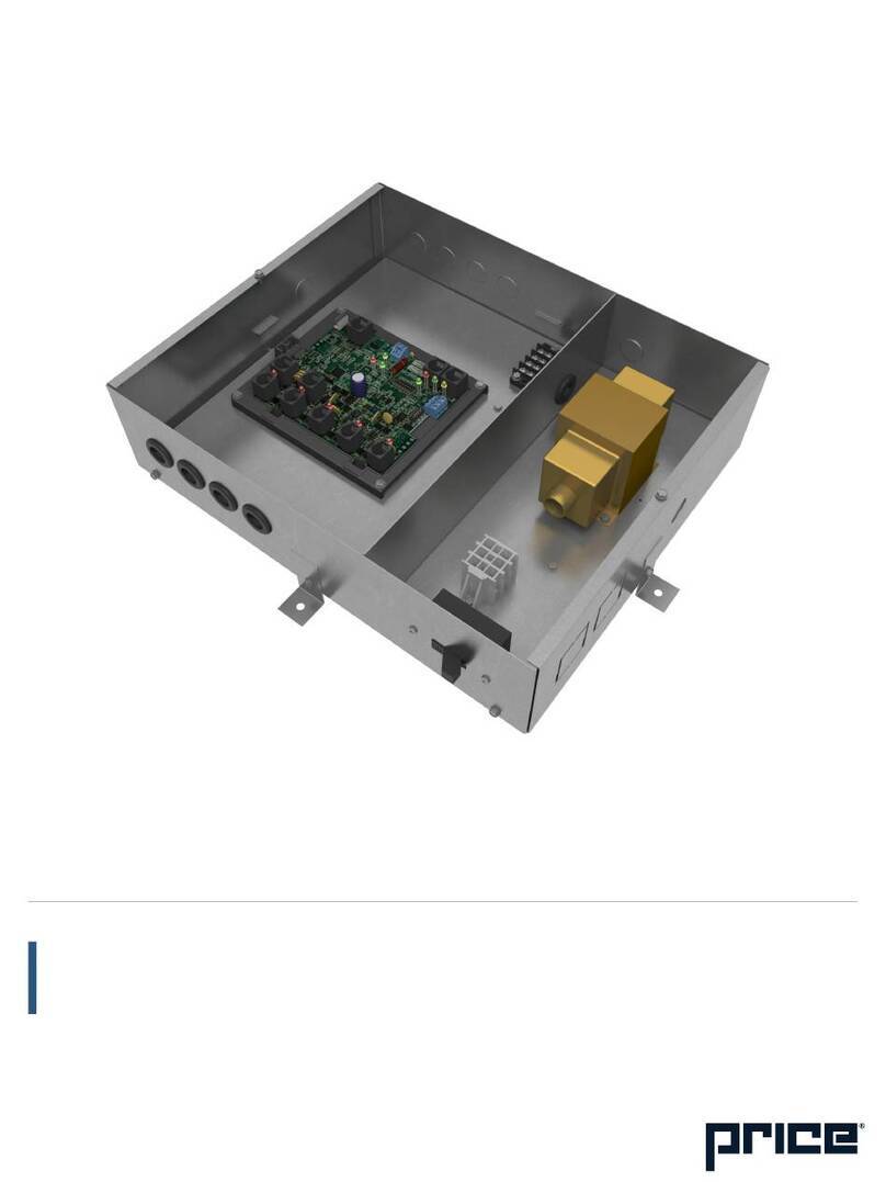
Price PP1 User manual

MANUAL – INSTALLATION + SERVICE
Power and Control Module
Plenum Pressurization - PP1
v000 –Issue Date: 01/30/19
© 2019 Price Industries Limited. All rights reserved.

PCM - PLENUM PRESSURIZATION
TABLE OF CONTENTS
Product Overview
Plenum Pressure Control............................................... 1
Control Methods ........................................................... 1
General Description....................................................... 2
Remote Pressure Node ................................................. 3
Features of the PCM ..................................................... 3
Installation & Mounting Instructions
Installing the PCM ......................................................... 4
Input/Output Description ............................................... 5
Wiring ........................................................................... 6
Thermostat Installation .................................................. 7
How to use Thermostats ............................................... 8
Display Navigation
Initial Startup ................................................................. 9
Info Menu.................................................................... 10
Service Menu .............................................................. 11
Temperature Setpoint Menu ........................................ 14
Service Menu - Input Menu ......................................... 15
Service Menu - Output Menu ...................................... 16
Output Menu - Heat .................................................... 17
Output Menu - Cool .................................................... 18
Output Menu - Room Lights........................................ 19
Address Menu............................................................. 20
Stat Setup Menu ......................................................... 21
Networking & Setup
BACnet Networking and Setup ................................... 22
Setting the Device Instance ......................................... 23
LINKER - USB Service Tool ......................................... 24
Troubleshooting........................................................... 25
Hardware Specifications.............................................. 27

1
priceindustries.com |PCM - PLENUM PRESSURIZATION - Manual
PCM - PLENUM PRESSURIZATION
PRODUCT OVERVIEW
Plenum Pressure Control
Office spaces are one of the more diversely loaded spaces which, in underfloor applications, can share a common pressurized
plenum. Diffusers and grilles for underfloor air distribution (UFAD) are selected based on a designed floor static pressure. This
demands maintaining floor pressurization for proper comfort and system operation. Pressure nodes that are concealed within
the floor diffusers are used to monitor the pressure differential in the plenum and space. Underfloor pressure controllers must be
capable of handling very low pressure resolution, on the order of 0.001 in. w.g. or less. Typically, plenum pressure set-points range
from as low as 0.05 in. w.g. to 0.08 in. w.g.
FAN COLUMN ADJUSTMENT
PLENUM SUPPLY DAMPER ADJUSTMENT
Control Methods
Fan Column Adjustment
Plenum pressure can be controlled by
the PCM via a 0-10 VDC analog output
to the Variable Frequency Drive (VFD)
installed on the fan column. The fan
column can be controlled to maintain
a constant pressure within the plenum,
adjusting to compensate for opening
and closing of dampers on the installed
diffusers and grilles. Alternatively, the
plenum pressure setpoint can be altered
based on space load to achieve the
desired space setpoint.
Plenum Supply Damper Adjustment
If Underfloor Deflection Grilles with
Dampers (DGD) are installed, these can
also be controlled by the PCM. Daisy
chained together, up to twelve DGDs
can be controlled via a Price plug-and-
play cable to modulate the air being
supplied to the underfloor plenum.
Similar to modulation of the fan column,
supply air can be adjusted using either
a constant or variable plenum pressure
control sequence.

2PCM - PLENUM PRESSURIZATION - Manual |priceindustries.com
PCM - PLENUM PRESSURIZATION
Product overview
General Description
PCM - Underfloor Pressure Controller
The Price PCM with BACnet can control up to 12 plenum dampers, controlling the amount of airflow that enters the underfloor
plenum. By reading static pressure sensor inputs, the PCM can monitor and regulate the very low static pressure required by
typical underfloor plenums.
The PCM can be wired to multiple Price RPN (Relative Pressure Node) sensors or to third-party static pressure sensors. The
outputs can operate DGD (Underfloor Deflection Grille) dampers or third-party dampers. The PCM features native BACnet
connectivity and is, therefore, able to be networked to a BAS through easy plug-and-play connections.
PCM- UNDERFLOOR PRESSURE CONTROLLER
* This is used for BACKET MS/TP and not an Ethernet connection
T-STAT PORT FOR
THERMOSTAT
CONNECTION
4 ANALOG OUTPUTS
(0-10 DC) 10MA MAXIMUM
TEMPERATURE
PROBE INPUT
2 RJ12
CONNECTIONS
(CONNECT TO DGD’S)
3 ANALOG INPUTS
24VAC BINARY
OUTPUTS
SERVICE PORT
FOR PRICE LINKER
PLUGGABLE
BACNET T-BLOCK
(TERMINALS NET
COM, A/+, B/-)
PLUGGABLE 24VAC
POWER TERMINAL
RJ45 BACNET PORTS*

3
priceindustries.com |PCM - PLENUM PRESSURIZATION - Manual
PCM - PLENUM PRESSURIZATION
INSTALLATION & MOUNTING INSTRUCTIONS
REMOTE PRESSURE NODE
Remote Pressure Node
Plenum pressure relative to room pressure is measured using
Remote Pressure Nodes (RPN). The RPN fits inside any
style mounting ring and under any Price round floor diffuser.
This maintains a consistent look with the installed diffusers.
The RPN is equipped with an extremely sensitive pressure
transducer, providing the measurement of small differential
pressures with less than 1% error, which is critical to underfloor
applications. This integral pressure transducer is powered via
24 VAC, and outputs a 1-10 VDC signal which is sent to the
PCM to regulate plenum pressure.
Features of the PCM
• BACnet network capabilities that allow the PCM to be
networked to a BAS.
• Output terminal blocks used to convey power and control
signal to as many as 12 remote plenum dampers.
• Up to three input terminal blocks used to accept static
pressure sensor ratings.
• ETL certified with transformer, circuit board, terminal blocks,
and all necessary hardware for trouble-free installation and
startup.
• 96VA Class 2 transformer.
• Available with thermostat input for temperature-dependent
pressure regulation (Room Sensor, Dial, LCD, LCD
with Motion Sensor, and LCD with CO2 and Humidity
Monitoring).
• Constant pressure regulation or variable pressure regulation
based on room temperature.
• Plenum temperature monitoring.
RPN plate
Keyed edge
to lock in
mounting ring
Pressure
sensor
(under side)

4PCM - PLENUM PRESSURIZATION - Manual |priceindustries.com
PCM - PLENUM PRESSURIZATION
INSTALLATION & MOUNTING INSTRUCTIONS
Installing the PCM
1. Place the PCM in the underfloor plenum in the center of
the controlled zone using a 35 ft. cable.
2. Supply power and ground to terminal per wiring diagram.
THIS TASK MUST BE COMPLETED BY A CERTIFIED
AND LICENSED ELECTRICIAN.
3. Connect up to three RPN pressure transducers using field
wired cable to the analog input terminals on the PCM.
4. If variable pressure sequence (9841) is used, run
thermostat wire to thermostat, and plug into “T-Stat” port
on the PCM. (For thermostat installation reference the
Installation & Mounting Instructions Thermostat Installation
section.
5. Connect BACnet network (if used). For more detailed
information on networking with PCM reference the Display
Navigation Address Menu section.
6. Flip the PCM’s power switch to the ON position.

5
priceindustries.com |PCM - PLENUM PRESSURIZATION - Manual
PCM - PLENUM PRESSURIZATION
INSTALLATION & MOUNTING INSTRUCTIONS
Input/Output Description
24VAC Binary Outputs Binary Output for On/Off control of fan. Multiple configurations. For example:
BO1 – Open Aux binary output available.
BO2 – Plenum Damper Plenum damper open. Used for floating point actuators.
BO3 – Plenum Damper Plenum damper closed. Used for floating point actuators.
BO4 – Open Aux binary output available.
BO5 – Open Aux binary output available.
Analog Outputs
AO1 – Open Aux analog output available (0-10VDC).
AO2 – Open Aux analog output available (0-10VDC).
AO3 – Open Aux analog output available (0-10VDC).
AO4 – Open Used to control variable fan or 0-10V actuators (0-10V output).
BO5 – Open Aux binary output available.
Analog 0-10VDC Inputs
Primary Pressure Sensor Primary remote pressure sensor (RPN). A minimum of one sensor (primary) is required for operation.
Secondary Pressure Sensor Additional RPN. Controller uses average of these inputs.
Tertiary Pressure Sensor Additional RPN. Controller uses average of these inputs.
Additional Inputs
AI1 – 5VDC Sensor Typically used for voltage monitoring over BACnet network.
Contact Closure Configurable Binary Input can be used for night setback, damper force open/close etc.
AI3 – T1 Thermistor Analog Input for temperature probe hookup with 10k Type J Thermistor.
Typically used for temperature monitoring over BACnet network.
Can also be configured for heat/cool changeover if required.
AI8 – T2 Thermistor Typically used for temperature monitoring over BACnet network.

6PCM - PLENUM PRESSURIZATION - Manual |priceindustries.com
PCM - PLENUM PRESSURIZATION
INSTALLATION & MOUNTING INSTRUCTIONS
Wiring
Below is an example of a typical PCM sequence diagram – constant pressure application. Each PCM has a sequence pre-
programmed at the factory, however many adjustments can be made in the field with either an LCD thermostat or the USB
LINKER service tool.
Power Soue
NOTE2:
primary vo s i[D� I
r/ Price PCU ,-�
Pressure
Controller r
Undeloor
236981-600
1
I
I
I
I
I
NOTE3:
I
-- I
I I
._ ___ _
__ I
____ ____ _
____
NOTE6:
LCD-SETUP ol
•---------
NOTES:
of
o�
H
C
NOTE4:
of
: �T
Cool Room
Condition
L .. _

7
priceindustries.com |PCM - PLENUM PRESSURIZATION - Manual
PCM - PLENUM PRESSURIZATION
INSTALLATION & MOUNTING INSTRUCTIONS
Thermostat Installation
General Description
The PCM Thermostats are all physically the same size and
mounting instructions will be typical.
Location
1. The PCM Thermostats must be mounted to a wall and
wired to the controller via the supplied plenum rated
CFLEX cable. This cable plugs into the thermostat and the
PCM controller with the ease of RJ-45 connections.
NOTE: The cable run can be extended using a Price cable
coupler and an additional CFLEX cable.
2. Mount the required thermostat in a place that is
convenient for the end user, but the following should be
taken into consideration:
• Do not mount a thermostat in direct sunlight i.e. across
from a window where heat can alter the temperature
reading.
• Should not be installed on an outside wall.
• Keep away from hot equipment like computers,
monitors and heaters etc.
• Ensure nothing will restrict vertical air circulation to the
thermostat. (Do Not Cover)
• Ensure wall is NOT pressurized! Hot/Cold air from a
pressurized wall will blow directly onto the thermostat’s
temperature sensor causing inaccurate readings.
Installation
1. The back plate on each thermostat is removable and can
be mounted to a standard electrical box or directly to
drywall using anchors supplied by others.
2. Run the CAT-5 cable through the center hole in the plate
and connect the cable to the thermostat. Then, secure the
thermostat onto the wall plate by inserting the top portion
of the thermostat first, then snapping the bottom half in.
3. All thermostats will come equipped with a 0.050 in. Allen
Key for the set screw at the bottom.
Careful thermostat installation will reduce field issues! Do
not twist or kink the blue CAT-5 thermostat cable. Damaged
cables are difficult to troubleshoot!
Thermostat cable product code: PIC-CABLE
TECH TIP
www.priceelectronics.ca
Page 6 of 24
Thermostat Installation
Location
1. The Price Analog Controller (PAC) Thermostats mu st be mounted to a wall and wired to the PAC
controller. The connecting cable screws into the thermostat and the PAC controller with the
supplied terminal blocks. Note: the cable run can beup to 70 ft.
2. Mount the required thermostat in a place that is convenient for the end user, but the following
should be taken into consideration:
•Do not mount a thermostat in direct sunlight i.e. across from a window where heat can
alter the temperature reading.
•Should not be installed on an outside wall .
•Keep away from hot equipment like computers, monitors and heaters etc.
•Ensure nothing will restrict vertical air circulationto the thermostat. (Do Not Cover)
•***Ensure wall is NOT pressurized! Hot/cold air fr om a pressurized wall will direct
blow onto the thermostat’s temperature sensor causi ng ‘bad’ readings. ***
Installation
1. The back plate on each thermostat is removable and can be mounted to a standard electrical box
or directly to drywall using anchors supplied by ot hers.
2. Run the cable through the center hole in the plate. Connect the cable to the thermostat, and then
secure the thermostat onto the wall plate inserting the top portion of the thermostat first, and then
snapping the bottom half in.
3. The thermostat will come equipped with a 0.050” Allen key for the set screw at the bottom.
How to use the Dial Thermostat
•The Dial Thermostat is powered from the PACcontroller.
•Measures room temperature and features a dial adju stment and an occupancy
button.
•Temperature Setpoint limits can be adjusted throug h free setup software using
the Price LINKER, or through an LCD Setup Stat.
•Simply use the adjustable dial for temperature adj ustment.
•Occupancy button can be used to override the systemduring unoccupied
times. Default setting is 4hrs.
T
ECH TIP: Careful thermostat installation will reduce field
issues! Do not twist or kink the thermostat cable.
Damaged cables are difficult to troubleshoot!
1.25" (32MM)
WALL FASTENERS
BY OTHERS
PLENUM RATED CFLEX CABLE INCLUDED
SURFACE MOUNT DETAIL

8PCM - PLENUM PRESSURIZATION - Manual |priceindustries.com
PCM - PLENUM PRESSURIZATION
INSTALLATION & MOUNTING INSTRUCTIONS
How to use Thermostats
Room Sensor Thermostat
• The Room Sensor Thermostat is powered from the controller.
• Measures room temperature.
• Setpoint can be adjusted from a hidden dial on the back of the thermostat using a
small flat-head screw driver.
• Setpoint limits can be adjusted through free setup software using the Price
LINKER, or through a BACnet system.
• Eliminated problem of unauthorized tampering with the thermostat.
• Occupancy button can be used to override the system during unoccupied times.
Default setting is 4 hours.
Dial Thermostat
• The Dial Thermostat is powered from the controller.
• Measures room temperature and features a dial adjustment and an occupancy
button.
• Temperature Setpoint limits can be adjusted through free setup software using the
Price LINKER, or through a BACnet system.
• Simply use the adjustable dial for temperature adjustment.
• Occupancy button can be used to override the system during unoccupied times.
Default setting is 4 hours.
• LED light indicates what mode the thermostat is in. One blink is cooling mode,
two blinks is heating mode, three blinks is neutral.
LCD Thermostat
• The LCD Thermostat is powered from the controller and has a variety of features.
• Measures room temperature and features an LCD screen with push button day
Setpoint adjustment.
• Temperature Setpoint limits are set through the thermostat setup menus, free
setup software using the Price LINKER, or through a BACnet system.
• Balancing and additional setup functions also available through the menus.
• [Optional] Add CO2 and humidity monitoring with PIC-TS-CO2H
LCD Thermostat with Motion Sensor
• The LCD Thermostat with Motion Sensor is powered from the controller and has a
variety of features as well.
• This model measures room temperature, features an LCD screen with day
Setpoint adjustment, and motion sensor with lighting control.
• Temperature Setpoint limits are set through the thermostat setup menus, free
setup software using the Price LINKER, or through a BACnet system.
• Balancing and additional setup functions are also available through the menus.
• This model is equipped with a motion sensor to determine occupancy of the
space. This sensor can also be used to control lighting.
ROOM SENSOR THERMOSTAT
DIAL THERMOSTAT
LCD THERMOSTAT
LCD THERMOSTAT W/ SENSOR

9
priceindustries.com |PCM - PLENUM PRESSURIZATION - Manual
PCM - PLENUM PRESSURIZATION
DISPLAY NAVIGATION
Initial Startup:
(LCD & Motion Thermostat only)
When the LCD thermostat is powered from the PIC, it will display the following information:
PRICE ELECTRONICS Start-up screen.
LCD THERMOSTAT
STANDARD MODEL Standard/Motion model.
LCD THERMOSTAT
VERSION X.XX Displays firmware version of thermostat.
LOADING: INITIALIZING Loading parameters.
PCM VERSION X.XX Controller type and controller firmware version.
SEQUENCE XXXX Displays sequence programmed into stat.
NOTE: A sequence number of 0 means the stat has NOT been calibrated.
MAC ADDRESS XXX Displays current MAC Address.
DEVICE INST. XXXXXX Displays device instance.
CURRENT PRESS
0.050 IN H20 (For example)
Changing the Setpoint – LCD & Motion Thermostat only
Day Setpoint Adjustment. Increase and decrease push buttons for Day Setpoint adjustment
DAY SETPOINT
75.0°F
DAY SETPOINT
SAVING...

10 PCM - PLENUM PRESSURIZATION - Manual |priceindustries.com
PCM - PLENUM PRESSURIZATION
DISPLAY NAVIGATION
Info Menu
(LCD & Motion Thermostat only)
The info menu shows information about the controller status regarding room load, damper position and BACnet Address info. No
values can be changed from this menu and it is not locked or protected in any way.
Press ‘Enter Menu’ button to enter the User Menu, scroll through using the up and down buttons.
OCCUPANCY ON
VVT MODE The Occupancy can be determined by the contact closure, motion or by a user pressing a button.
THERM READING Temperature reading from T1 Sensor.
DAMPER POS. This indicates the current position of the damper as a (%). Range is 0-100% (100% = full open or maximum air).
DAMPER TARGET This indicates the damper position as a (%) the controller is targeting. Range is 0-100% (100% = full open or maximum air).
AI4 PRESSURE Current pressure reading on AI4 in in. w.g.
AI5 PRESSURE Current pressure reading on AI5 in in. w.g.
CURRENT PRESS Current final pressure reading in in. w.g.
PRESS TARGET Current pressure target in in. w.g.
AO4 OUTPUT Current output on the AO4.
AIRHANDLER IS ACTIVE Controller will sense airflow if the air handler is running. If no air is present, the display will read Not Active.
MAC ADDRESS 1 Shows the BACnet MAC address. Range 1-99. MAC Addresses can be set via dip switch or through software in the thermostat.
DEVICE INSTANCE (Instance must be “globally” unique on your site) Displays controller’s BACnet Device Instance (If BACnet is attached). Device
Instance can range from 0-4, 194, 303.
PRESS MENU TO EXIT NOTE: Service menu will automatically time out after 20 seconds.

11
priceindustries.com |PCM - PLENUM PRESSURIZATION - Manual
PCM - PLENUM PRESSURIZATION
DISPLAY NAVIGATION
Service Menu
(LCD Thermostat only)
Hold down the ‘Menu’ button for 5 seconds, display will show ‘Passcode:’
Use ‘Up’ and ‘Down’ keys to enter the password in this sequence: Down – Up – Up – Down.
PRESS SETUP Change the application the unit is operating as.
TEMP SETPOINT (Variable Pressure application only) – page #.
INPUT Shows sensor readings, settings, and configuration.
OUTPUT Allows setup of Damper, Heat, Cool, outputs. Allows setup of room light output (motion stat only).
BACNET Allows setup of BACnet addresses. MAC address, Device Instance, Baud Rate.
STAT SETUP Allows setup of LCD back lighting, sounds, motion sensor. Adjustment of HVAC and room lighting time-outs.
PRESS MENU TO EXIT NOTE: Service menu will automatically time out after 20 seconds.

12 PCM - PLENUM PRESSURIZATION - Manual |priceindustries.com
PCM - PLENUM PRESSURIZATION
DISPLAY NAVIGATION
Service Menu
PRESS APP: CONST. PRESS Regardless of room condition, the pressure controller will maintain plenum pressure at the pre-
selected pressure setpoint (default: 0.05 in. w.g.)
VAR. PRESS Controller will decrease or increase static pressure based on room temperature
CONSTPRESSBYP Throttles the bypass valve to maintain constant pressure setpoint
VAR.PRESSBYP Controller will decrease or increase static pressure based on temperature
PRESS SP-COLD Sets cooling pressure setpoint (Constant Pressure application only)
PRESS SP-HOT Sets heating pressure setpoint (Constant Pressure application only)
NOM.PRESS.COLD In. w.g. (Variable Pressure application only) Controller will target between this value and cooling
values based on duct air when PI is less than zero.
MINPRESS-COLD Sets the cool min pressure. Must be lower than (or same as) cool max pressure (Variable
Pressure application only).
MAXPRESS-COLD Sets the cool max pressure. Must be higher than (or same as) cool min pressure (Variable
Pressure application only).
NOMPRESS-HOT In. w.g. (Variable Pressure application only) Controller will target between this value and heating
values based on duct air when PI is greater than zero.
MIN PRESS-HOT Sets the hot min pressure. Must be lower than (or same as) heat max pressure. (Variable
Pressure application only).
MAX PRESS-HOT Sets the hot max pressure. Must be higher than (or same as) heat min pressure (Variable
Pressure application only).
UNOCC PRESSSP Deadband on either side of the pressure set point [ default .0.03 in. w.g.]
PRESSDEADBAND Maximum amount that output will be charged per step. Range 1-50 [default 5%].
MAX STEP Maximum amount that output will be charged per step. Range 1-50 [default 5%].

13
priceindustries.com |PCM - PLENUM PRESSURIZATION - Manual
PCM - PLENUM PRESSURIZATION
DISPLAY NAVIGATION
Service Menu
DIVIDER Default 250 Used to increase and decrease damper speed (damper step)
NEARPRESS.PNT In. w.g. Near Pressure Setpoint - Reduces damper steps as it nears this pressure setpoint.
STL TIME-NEAR 120 sec how long it slows the damper when within the pressure setpoint.
STL TIME-FAR 20 sec how long it increases the damper movements when outside the pressure setpoint.
DETECTAH.SHDN
NO Detect Air Handler Shutdown: YES – Occupied and unoccupied modes triggered by pressure.
(If enabled day pressure and night pressure trip trigger occupied/unoccupied mode). NO –
occupied and unoccupied modes not triggered by pressure.

14 PCM - PLENUM PRESSURIZATION - Manual |priceindustries.com
PCM - PLENUM PRESSURIZATION
DISPLAY NAVIGATION
Temperature Setpoint Menu
(Variable Pressure application only. Setpoint Limits and Temperature Units)
Scroll through menu with Up and Down keys.
Press ‘Enter/Menu’ button to apply your changes. *---Saving---* will display as your changes are applied.
SET LOW LIMIT 65.0F • This is the lowest setpoint allowed.
• Range: 10.0°F – 100.0°F Default: 65.0°F
SET HIGH LIMIT 80.0F • This is the highest setpoint allowed.
• Range: 10.0°F – 100.0°F Default: 80.0°F
TEMPERATURE UNITS
FAHRENHEIT
• Fahrenheit or Celsius.
• Default: °F
NIGHT HEAT SET 62.0F • PIC will maintain this heating setpoint when unoccupied.
• Range: 10.0°F – 100.0°F Default: 65.0°F
NIGHT COOL SET 83.0F • PIC will maintain this cooling setpoint when unoccupied.
• Range: 10.0°F – 100.0°F Default: 83.0°F
PROPORTIONAL BAND
2.0F
• Default 2°F, 1°C
• Proportional Band is the range of control or the throttling range of the device.
DAY DIFFERENTIAL 1.0F • 1°F, 0.5°C
• Day differential is the deadband on either side of the setpoint.

15
priceindustries.com |PCM - PLENUM PRESSURIZATION - Manual
PCM - PLENUM PRESSURIZATION
DISPLAY NAVIGATION
Service Menu – Input Menu
Scroll through menu with Up and Down keys.
Press ‘Enter/Menu’ button to apply your changes. *---Saving---* will display as your changes are applied.
#OF SENSORS 2 Number of sensors connected to the PCM.
SENSOR MODE • Average (Default) – Gathers all sensor readings and averages them.
• High Value – Uses only high sensor values. Low Value – Uses only low sensor values.
SENSOR RANGE Default: 0.250 in. w.g.
CURRENT PRESS Current pressure reading in in. w.g.
SUPPLYAIRTEMP Current Supply air temperature.
NEUTRAL MODE
DYNAMIC
• When supply air temperature (SAT) is below room temperature is considered cooling.
• When supply air temperature (SAT) is above temperature is considered heating.
• Neutral Mode = Conventional, Force Cool, Force Heat.
• Conventional uses Hot and Cold switch points.
• Force cool, Force Heat always assumes cold or hot.
• Not recommended.
SAT OFFSET 0.0F Apply an offset to the SAT temperature.
CONTACTCLOCFG Not used, Unoccupied on close, Occupied when closed, Damper full open, Damper full closed.
CO2 SENSOR DETECTED • Indicates that the CO2 sensor is connected.
CO2 TWEAK 0% • Percentage that the CO2 reading can be tweaked if required.
• Default is 0%.
CO2 OFFSET 0PPM Value to offset CO2 reading if required.
Default 0 PPM.
HUMIDITY SENSOR
DETECTED Indicates that the humidity (RH) sensor is connected.
HUMIDITY TWEAK • Percentage that the RH reading can be tweaked if required.
• Default 0%.
HUMIDITY OFFSET • Value of offset RH reading if required.
• Default 0% RH.
PRESS MENU TO EXIT

16 PCM - PLENUM PRESSURIZATION - Manual |priceindustries.com
PCM - PLENUM PRESSURIZATION
DISPLAY NAVIGATION
Service Menu – Output Menu
Scroll through menu with Up and Down keys.
Press ‘Enter/Menu’ button to apply your changes. *---Saving---* will display as your changes are applied.
DAMPER & AO4 BO2&3 USED AS
DAMPER Assign use of BO2 and BO3 to reheat or damper.
DPR. RUNTIME
95SEC. Change the total runtime of damper.
DPR. DIRECTION
NORMAL Changes which direction open and close are set to.
AO4 MIN
0.0 VDC • Default 0.0VDC.
AO4 MAX
10.0 VDC
• Set maximum output voltage.
• Default 10.0 VDC.
BO1 & AO1 ECM COOL MIN
1.5 VDC
• PI cooling min (-1 to – 100%) output voltage.
• Default 1.5 VDC.
ECM COOL MAX
8.0 VDC
• PI cooling max (-100%) output voltage.
• Default 8.0 VDC.
ECM HEAT MIN
1.5 VDC
• PI heating max (+100%) output voltage.
• Default 1.5 VDC.
ECM HEAT MAX
8.0 VDC
• PI heating min (+1 to +100%) output voltage.
• Default 8.0 VDC.
ECM DEADBAND
1.5 VDC
• PI in neutral/deadband.
• Default 1.5 VDC.
ECMUNOCCUPIED
1.5 VDC
• Controller in occupied mode.
• Default 1.5 VDC.
BINARYFANTYPE
This controls the binary FAN output
·No Fan: Fan output disabled
·Heating: Fan on when PI heating (+1 to + 100%) (Day & night mode)
·DAY & NIGHT HEAT: During the day, fan is always one. During the night, the fan is only on
when PI is heating (+1 to +100%)
·CONTINUOUS: Fan always one
·DAY AND NIGHT HEAT/ COOL: During the day, fan is always on. During the night, the fan is
only on when PI is heating or cooling (+1 to + 100%)
·HEAT AND COOL: Fan is on when PI is heating or cooling (+1 to +100% or -1 to – 100%)

17
priceindustries.com |PCM - PLENUM PRESSURIZATION - Manual
PCM - PLENUM PRESSURIZATION
DISPLAY NAVIGATION
Output Menu - Heat
(Setup of Heat Outputs)
Scroll through menu with Up and Down keys.
Press ‘Enter/Menu’ button to apply your changes. *---Saving---* will display as your changes are applied.
REHEAT TYPE: BINARY
•Reheat Type: Binary, Hot water, Binary/PWM, Hot Water/PWM.
•Binary uses Stage 1, 2, 3 –Default.
•Binary/PWM and Hot Water/PWM – Stage 3 is PWM.
DRIVE TIME
90 SECONDS
•Hotwater runtime in seconds.
•Not shown if BINARY heat is used.
HEAT STAGE 1 1% •Heat Stage 1 Trip Point: Stage 1 engages at 1% heating.
•Not shown if hot water heat is used.
HEAT STAGE 2 50% •Heat Stage 2 Trip Point: Stage 1 engages at 50% heating.
•Not shown if hot water heat is used.
HEAT STAGE 3 100% •Heat Stage 3 Trip Point: Stage 1 engages at 100% heating.
•Not shown if hot water heat is used.
REHEAT FAIL SAFE OFF •Off- Outputs sends 24 VAC on call for heat.
•On- Outputs send 24VAC when no call for heat (fail open valve in cold climates – ie: Winnipeg).
ANALOG HEAT MIN
0.0 VDC Outputs this voltage on heat analog pin when there is a minimum call for heating.
ANALOG HEAT MAX
10.0 VDC Outputs this voltage on heat analog pin when there is a maximum call for heating.
ANALOG HEAT IDLE
0.0 VDC Outputs this voltage on heat analog pin when there is no call for heating.

18 PCM - PLENUM PRESSURIZATION - Manual |priceindustries.com
PCM - PLENUM PRESSURIZATION
DISPLAY NAVIGATION
Output Menu - Cool
(Setup of Cool Outputs)
Scroll through menu with Up and Down keys.
Press ‘Enter/Menu’ button to apply your changes. *---Saving---* will display as your changes are applied.
BINARY COOL 1% Binary Cool Trip Point: engages at 1% cooling load.
ANALOG COOL MIN
0.0 VDC Outputs this voltage on cool analog pin when there is a minimum call for cooling.
ANALOG COOL MAX
10.0 VDC Outputs this voltage on cool analog pin when there is a maximum call for heating.
ANALOG COOL IDLE
0.0 VDC Outputs this voltage on cool analog pin when there is no call for cooling.
Table of contents
Other Price Control Unit manuals