5
priceindustries.com |PCM - INTERIOR AND PERIMETER ZONES COOLING AND HEATING - Manual
PCM - INTERIOR AND PERIMETER ZONES COOLING AND HEATING
INSTALLATION & MOUNTING INSTRUCTIONS
4PCM - INTERIOR AND PERIMETER ZONES COOLING AND HEATING - Manual |priceindustries.com
PCM - INTERIOR AND PERIMETER ZONES COOLING AND HEATING
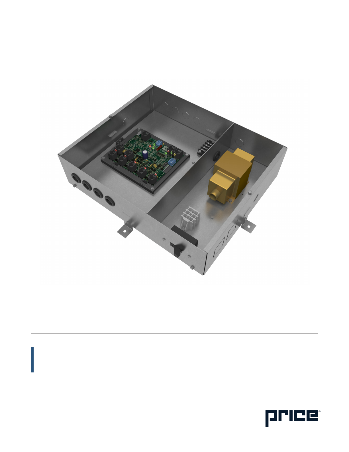
Product overview
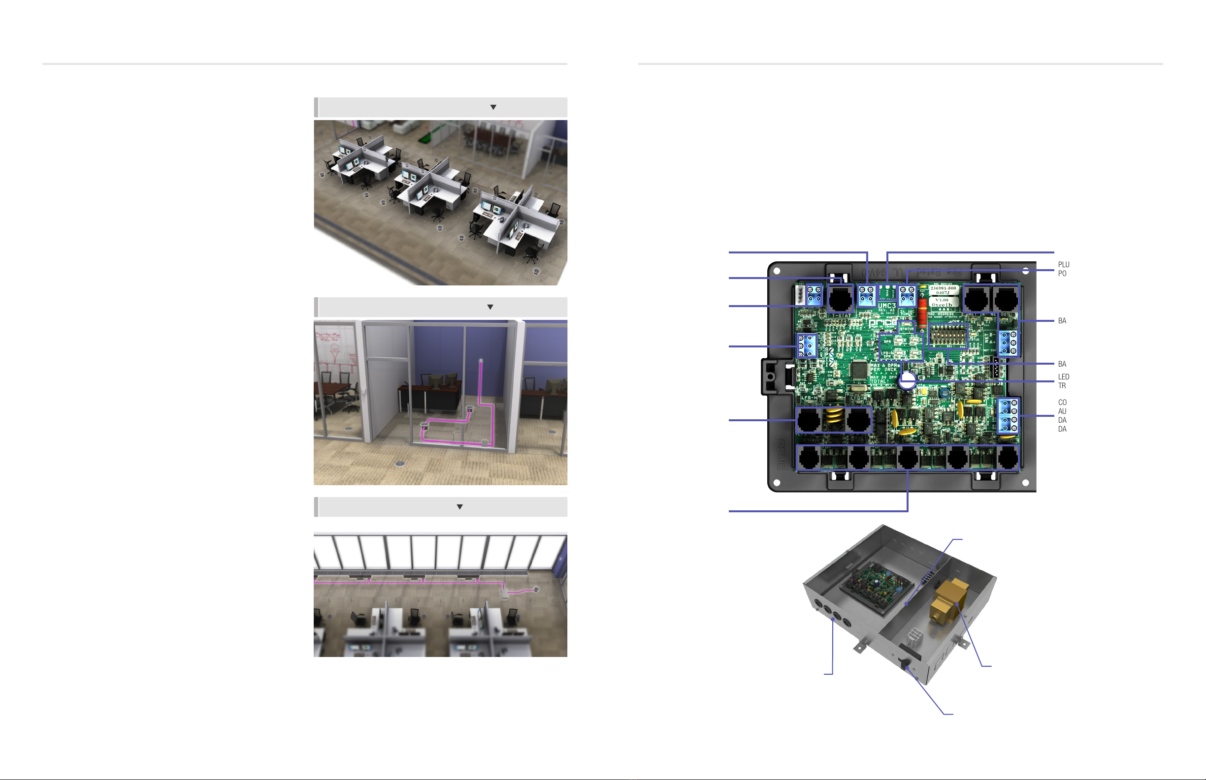
Features of the PCM
• Control up to 30 underfloor dampers.
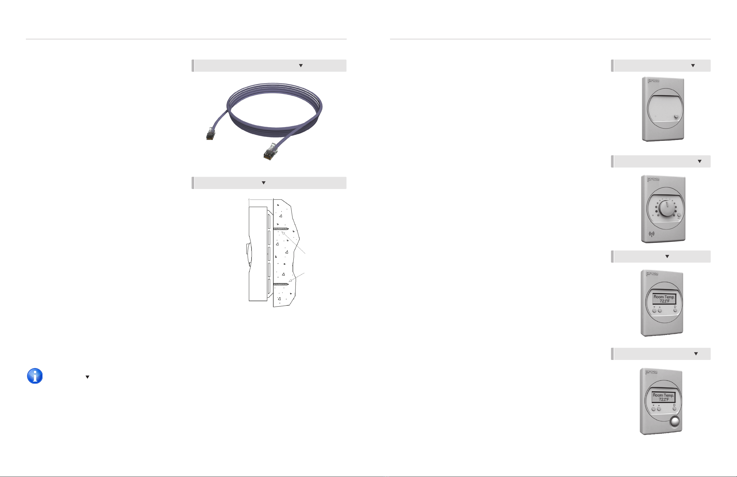
• Modular connections to dampers – Use RJ-12 cables
included with dampers to connect underfloor dampers to
PCM. LFGH dampers use RJ-45 connections.
• Outputs protected by self-resetting thermal fuses – Prevents
damage to circuit board in the event of a damaged cable.
Fault LED lights when dampers are trying to drive on an
output with damaged cable.
• Auxiliary 24VAC Binary Output – Use for reheat, room lights,
signal to other equipment, etc. Rated for a maximum output
of 0.5A (12VA).
• Auxilary Analog Outputs (2) – Use to connect to other
equipment, BAS, etc. Output range fully configurable (2-
10VDC, 0-10VDC, 10-2VDC, etc.). Rated at a maximum
output of 10mA each.
• Analog Inputs (2) – Configurable to allow control of the
PCM from a source other than a Price Thermostat (BAS,
third party thermostat, etc.). Accepts the standard dual
0-10VDC signal for cooling/heating. (if not using LFGH
or other heaters connected to PCM, only the 0-10V cooling
signal is needed).
• Input (1) 10K type J thermistor – Can be used to monitor a
temperature over the network. Can also be used for heat/
cool changeover.
• Thermostat port - For RJ-45 connection to thermostat from
the PCM controller.
• Native BACnet MS/TP communication – Connect using RJ-
45 cable, or use discrete twisted-pair wire to terminal block.
Available speeds: 9600, 19200, 38400, 76800 (default).
• LED Indication – For ease of troubleshooting – displays
status, damper directions, BACnet status, and output fault.
• Pluggable terminal blocks – For easy installation.
• High-Voltage disconnect switch.
• Max 100VA multi-tap transformer with circuit breaker.
• Metal safety guard separating high and low voltage areas.
• 4 grommeted openings for modular cable connections.
• Temperature sensor input (for monitoring).
• Disconnect switch.
• Pluggable 24VAC power terminal.
Operation
The PCM controller is an advanced and fully configurable
underfloor ModuFlex cooling controller. It is typically interfaced
with one of four Price Thermostats to determine room load and
allow for setup functions. With a variety of output configurations,
the PCM can control up to 30 underfloor dampers, as well as
auxiliary equipment using its auxiliary 24VAC binary outputs, and
analog 0-10V outputs.
Upon an increase in space temperature the controller regulates the
dampers open to increase the flow of cool air. On an increase
of space temperature greater than the proportional band,
the dampers’ positions are maintained at their pre-selected
maximum setting.
On a decrease in space temperature the controller regulates the
dampers closed to decrease the flow of cool air. If connected to
LFGH floor grills with integrated damper and reheat, the PCM
will energize or modulate the heat proportionally to the room
demand. If the space temperature decreases to less than the
proportional band, the dampers’ positions are maintained at
their pre-selected minimum setting.
The PCM can also be configured to accept 0-10V input signals
from a BAS system or third party thermostat for room load
calculations, instead of data from the thermostat.
The PCM can be used as a stand alone unit, or can be
interfaced into a BAS with the MS/TP BACnet network.
The PCM offers five thermostat options that provide a range of
control from room temperature sensing, all the way to motion
sensing. With the use of the LCD Thermostat, balancing and
system setup can be achieved. Further, with the use of the LCD
Thermostat with Motion, the PCM can be used as a motion-
occupied zone and lighting controller. The LCD Thermostat with
Motion offers different levels of sensitivity and still performs all
the functions of the regular LCD Thermostat.
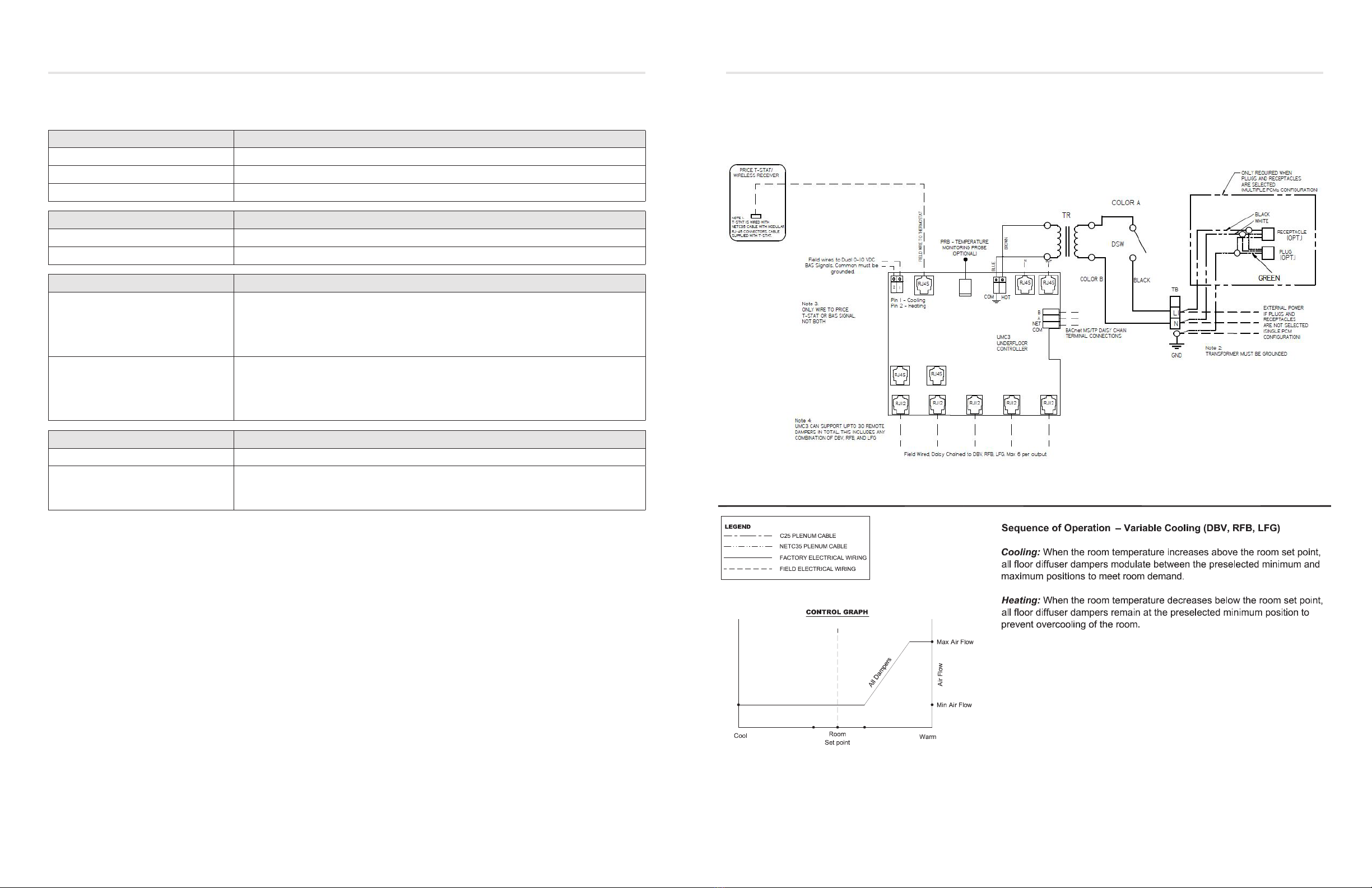
Installation
1. Before installation, make sure that Building installation
should have maximum of 20 A Circuit Breaker.
NOTE: PCM doesn’t contain any primary Protection and
entirely relies on protection from Building Installation.
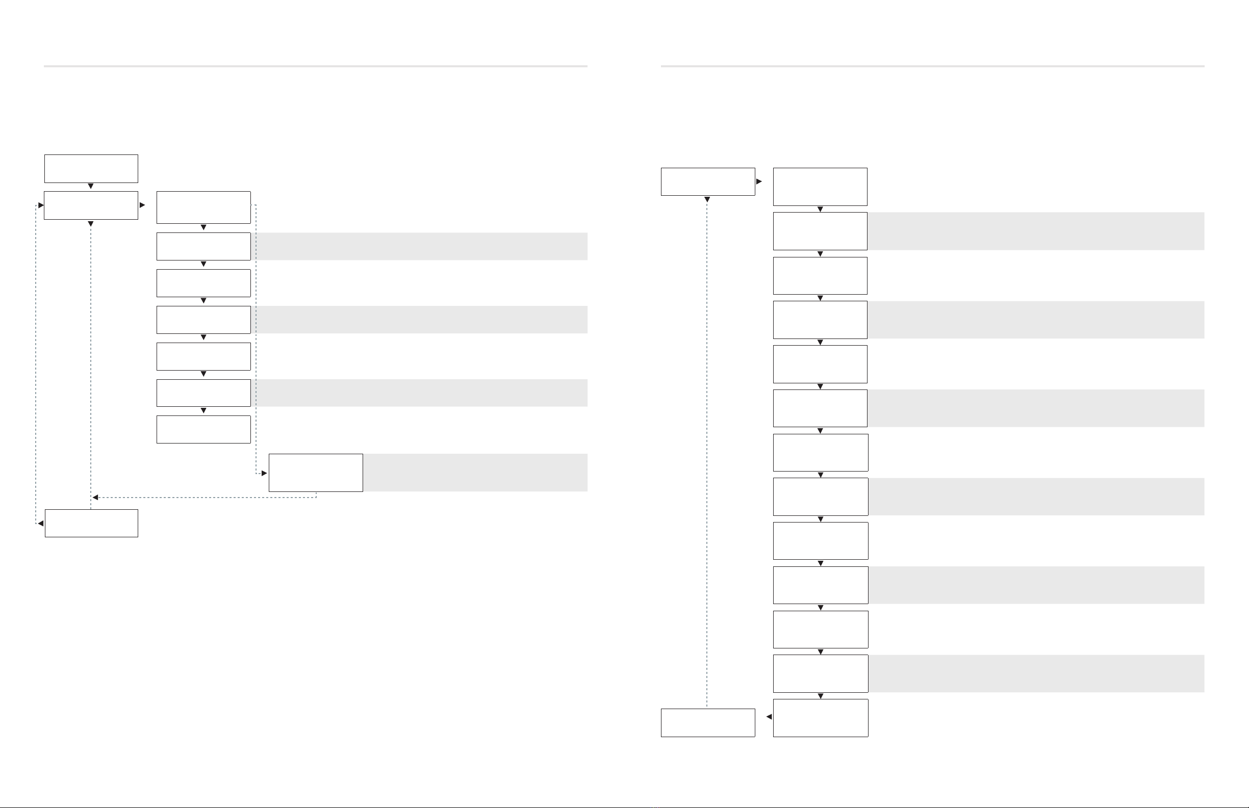
2. Place the PCM in the underfloor plenum in the center of
the controlled zone.
3. Supply power and ground to terminal per wiring diagram.
NOTE: This task must be completed by a certified and
licensed electrician.
4. Connect underfloor dampers using CFLEX cables supplied
with dampers. Follow these general rules:
A. Connect no more than 30 dampers total
B. Daisy chain up to 6 dampers per output – no more
C. Do not connect standard dampers (with RJ-12 plug) to
LFGH outputs (which use RJ-45 plug)
D. LFGH dampers (up to 12) count towards the maximum
of 30 dampers per controller
5. Run CFLEX thermostat cable to thermostat, and plug into
“T-Stat” port on the PCM. (For thermostat installation
reference the Installation & Mounting Instructions
Thermostat Installation section.)
6. Connect BACnet network (if used). For more detailed
information on networking with PCM reference the Display
Navigation Address Menu section.
7. Flip the PCM’s power switch to the ON position.
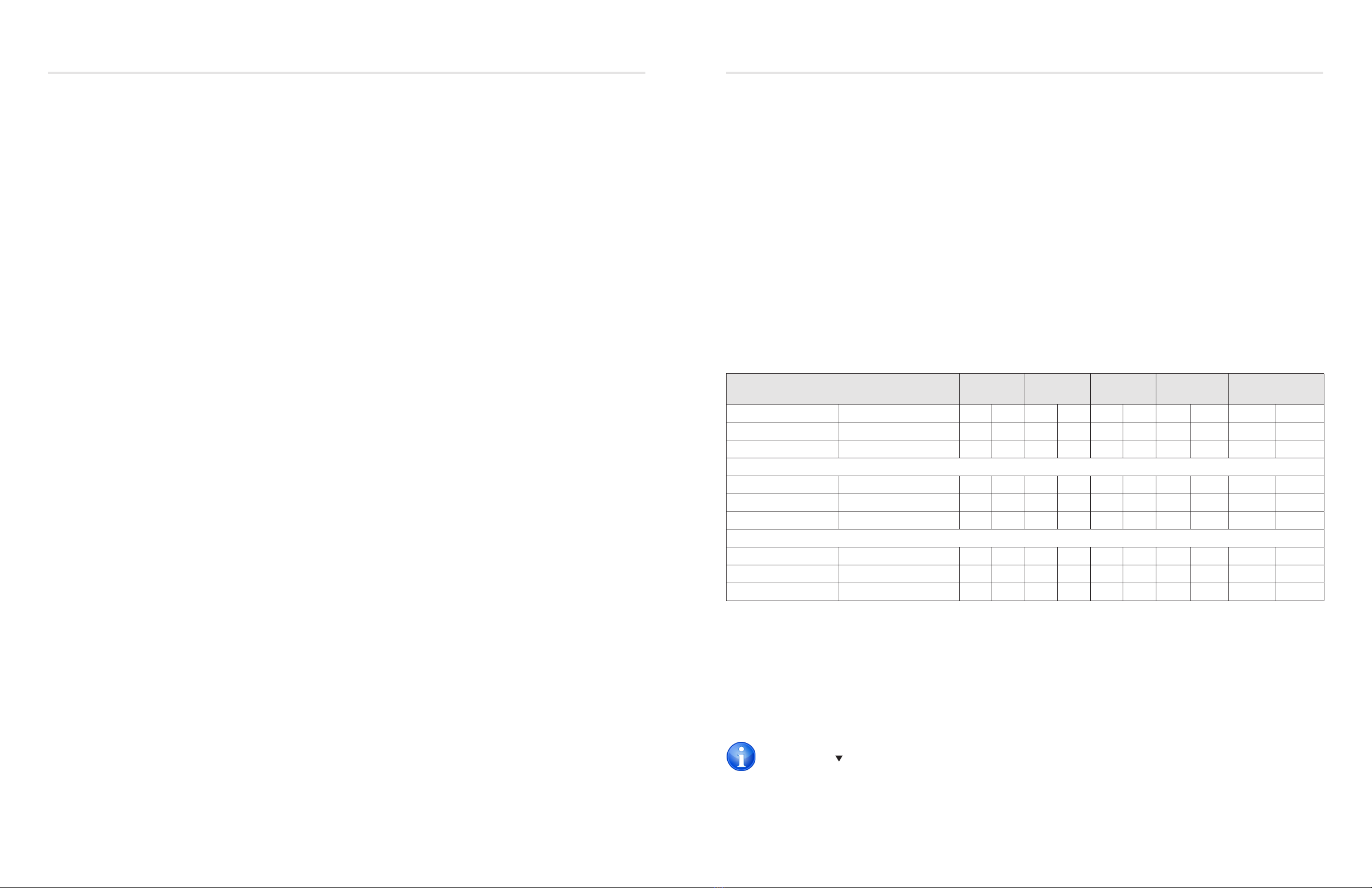
Price Flow Response Chart
HCCO Response Cooling
Min
Cooling
Flows
Heating
Min
Heating
Flows
Neutral Supply
Air Flow
PI = Cooling Supply air = Cold D L
PI = Heating Supply air = Cold D L
PI = Neutral Supply air = Cold D L
PI = Cooling Supply air = Hot D L
PI = Heating Supply air = Hot D L
PI = Neutral Supply air = Hot D L
PI = Cooling Supply air = Neutral D L
PI = Heating Supply air = Neutral D L
PI = Neutral Supply air = Neutral D L
“D” indicates the target of the regular dampers and “L” represents the target of the LFGH dampers (with integrated reheat)
NOTE 1: By default the PCM is shipped configured for cold supply air only. This can be changed to enable HCCO with thermistor
probe (however this will almost never be the case).
NOTE 2 : PI = Proportional Integral = room load (either cooling/neutral/heating)
Above is a flow response chart for the PCM, showing the demand, duct air condition, and the controller’s output.
E.g.: PI = Cooling, Supply Air = Cold, Output = Cooling Flows. This indicates that the room demand is in cooling, the supply air is cold,
and the controller would modulate both the regular dampers and the LFGH dampers between the Cool Min and Cool Max values.
Use the above table to determine what airflows are being chased in certain modes. Example: If PCM is trying to heat the room (PI = Heating)
and cool air is being supplied (Duct Air = Cold) it will chase its heating min flow.
TECH TIP