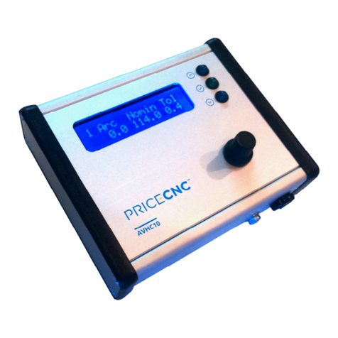
PRICECNC AVHC10 User manual

1
CNC Plasma Torch Height Controller
Installation and Operation Manual
Model: AVHC10 Revision: 1.2

2

3
SAFETY NOTICE
WHEN THIS DEVICE IS IN OPERATION, VOLTAGES
HAZARDOUS TO HEALTH AND HUMAN LIFE ARE
PRESENT INSIDE THE ISOLATION MODULE.
This device should only be connected by a qualified and authorized person.
Improper connection can cause serious injury or death. Prior to installation and
operation, carefully read the entire manual and be absolutely sure that you fully
understand and are able to make the sole decision to determine if you are capable of
a safe and proper installation. Remember that inside the Isolation Module, voltages
hazardous to health and life may be present.
There must be no physical contact with any electrical connections while this device
or any connected device is powered. Do not operate this product with wet hands, wet
gloves, or any wet clothing. Before turning the unit on, secure the safety of others,
and read and understand all instructions. If you have any questions or concerns, do
not continue.
Warning: Provide adequate protection for all risks associated with plasma cutting.
For more detailed information of the risk associated with plasma cutting, refer to your
plasma cutter's owner manual.
This device must be earthed/grounded in accordance with this installation guide,
earthing of non-electrified conductive parts (including device housings) is an
essential part of electrical safety.
Touching non-insulated and non-grounded elements can be fatal. Provide a safe
place for your device. After installation, securely protect against any physical contact
between the terminals on the Isolation Module and any person(s).
It is strictly prohibited to perform any repairs or modifications to this product,
performing either one of these actions could lead to serious injury or death to
yourself and/or others.
Terms of Use: By proceeding with the installation and use of this product, you fully
understand and agree that PRICECNC and their distributors are not liable for any
incident or event resulting in direct loss, indirect loss, injury to self or others, damage
to property, or loss or damage of any kind and that the end user assumes all risks. If
you do not agree to these terms in their entirety, proceed no further, and return this
product for a full refund.
If you have any questions or are unsure about anything stated in this manual, please
contact a PRICECNC dealer or service centre for assistance.

4
Contents
Introduction......................................................................................................................... 4
1 Installation........................................................................................................................ 5
1.1 High Frequency Plasma Cutter Interference ................................................................ 5
1.2 Earthing....................................................................................................................... 6
1.3 Raw Arc Measuring Point Connections........................................................................ 6
1.4 50:1 Measuring Point Connections .............................................................................. 6
1.5 Floating Z Axis (not included) ...................................................................................... 7
1.6 Anti-Dive...................................................................................................................... 7
1.7 AVHC10 Installation Wiring Diagram ........................................................................... 8
1.8 Wiring Definitions......................................................................................................... 9
2 AVHC10 Operation ......................................................................................................... 10
2.1 Display List ................................................................................................................ 11
3 Appendix ........................................................................................................................ 14
3.1 Setting up the AVHC10 in Mach 3......................................................................... 14
3.2 Setting up the AVHC10 in SheetCAM........................................................................ 16
Introduction
When using a CNC Plasma cutting table, good cut quality can only be achieved by
maintaining a consistent distance between the cutting torch and the material being cut. This
can be difficult to achieve as heat from the cutting process can warp the material being cut
or the material that is being cut may not be level or flat. To overcome these problems during
cutting, the cutting torch needs to be raised and lowered to compensate for changes in the
height of the sheet.
The PRICECNC Arc Voltage Height Controller measures the voltage between the plasma
torch and the material being cut, this is known as the ‘Arc Voltage’. As the distance between
the torch and the material changes during a cut, the voltage also changes. The greater the
distance, the higher the voltage and the smaller the distance the lower the voltage. By
measuring the changes in the Arc Voltage, the AVHC10 can continuously adjust the arc
length for optimum cutting performance.
Different materials types and thicknesses require different height controller setting. For
convenience, up to 30 different material or thickness settings can be saved on the AVCH10.

5
1 Installation
The PRICECNC Arc Voltage Height Controller has two main components. One is called the
‘User Interface’ and the other is called the ‘Isolation Module’. Both of these units need to be
connected to each other. The Isolation Module also connects to the plasma cutter and the
user interface also connects to a power supply and the signal inputs and outputs on the
breakout board.
In this installation example, we show how to install the PRICECNC AVHC10 on to a Plasma
CNC table with the following properties:
Design Software SheetCam
Work Software
MACH 3
Breakout Board 5-axis with 1 relay output and 5 inputs
PC to Breakout Board Interface
LPT
Parallel Printer Port
CNC Machine Custom/Homemade/DIY 3 Axis CNC Table with
Floating Z axis
Mechanical Drive Stepper Motors
Plasma Cutter R-Tech Plasma50CNC
1.1 High Frequency Plasma Cutter Interference
Some value plasma cutters use a high frequency, high voltage striking arc to strike across
the air gap between the plasma cutter electrode and the work piece. This striking arc can
generate massive electromagnetic fields which can interfere with surrounding electronics
including CNC motors, drive units, breakout board and Computers. This electromagnetic
field comes from the cables that connect the plasma cutter electrode to the plasma cutting
machine. Cables that are connected to this circuit can also spread interference. The
PRICECNC Arc Voltage Height Controller is designed to keep this interference away from
the CNC control circuitry by utilising a completely electrically isolated measuring circuit in the
Isolation Module. The Isolation Module is also supplied and fitted with a shielded cable that
provides the User interface with a clean signal for accurate measurement.

6
1.2 Earthing
To prevent the above mentioned High Frequency interference from becoming an issue on
your CNC plasma cutting equipment, proper earthing/grounding must be fitted using at least
16mm
2
(AWG 5) multi strand cable. In a typical 3 axis CNC plasma cutting setup, the
following components should be earthed direct to the star point:
•Arc Voltage Height Controller aluminium case.
•Fixed portion of table.
•Gantry
•Buggy
•Z axis travel plate
•Stepper/Servo motor control box
•Plasma Cutter case
The star point is a point where the earth wires from all of these individual items meet, this is
then connected to the earth electrode. The alternative to a star point earthing system is a
daisy chain earth system. This is not recommended as it is not as effective at preventing
interference.
1.3 Raw Arc Measuring Point Connections
For best results, the cables that connect the Isolation Module to the plasma cutter should be
protected from the effects of a bad connection on the circuit that carries the plasma current.
Sometimes rust or dirt on the work sheet can cause a poor clamp connection which can
create a voltage difference between the clamp and the work piece which would affect the
measured voltage used for controlling torch height. For best results, the black connection on
the Isolation Module should be connected to the work piece by a separate small clamp.
A poor connection on the torch cable can cause the same issue, for best results, the
connection from the Blue plug on the Isolation Module should be connected to the plasma
torch as close to the tip as safely possible. Preferably, where the flexible air/current hose
connects to the torch.
1.4 50:1 Measuring Point Connections
The 50:1 measuring circuit is designed to work with the 50:1 voltage divider output on a
Hypertherm Powermax 45 Plasma Cutter and other Plasma cutters that use the same
resistor network to create the 50:1 voltage. The Hypertherm Powermax 45 plasma cutter
uses 100,000 and 2,000 ohm resistors in series to produce the a 50:1 voltage across the
2,000 ohm resistor. The PRICECNC AVCH10 is calibrated for use with 50:1 voltage dividers
with these particular resistances. Other resistor values will work but the accuracy of the
measured voltage may be affected. The overall circuit resistance of the voltage divider
should not exceed 120,000 ohms.

7
1.5 Floating Z Axis (not included)
For best plasma cutting results, the height at which each cut in a job starts should be
measured by a floating Z axis. The floating Z axis operates a switch which activates the
Digitize/Probe input in Mach3 when the torch descends into the work piece. When this
method is used with the correct G-code (G31), the Z axis Digital Read Out (DRO) will be
reset to zero at the start of each cut. This compensates for uneven sheet height and
improves the cut quality.
1.6 Anti-Dive
A reduced feed rate is often used when cutting small holes or tight angles, this reduced feed
rate increases the arc voltage which will cause the AVHC10 to lower the torch into the work
piece. To prevent the torch diving into the work piece when a reduced feed rate is used,
Torch Height Control should be deactivated during the reduced feed rate. One way to
deactivate Torch Height Control is to use an anti-dive Macro in Mach 3. Unfortunately Mach
3 pauses the operation of the CNC machine momentarily while it executes the macro which
may result in poor cut quality (dings/notches).
To overcome this, the PRICECNC AVHC10 can take in a signal that blocks outgoing Raise
and Lower commands. Using the correct cut rules in SheetCAM, the Post Processor will
write G-code that includes a command to turn on and off a signal output on the breakout
board. This signal is received by the AVHC10, blocking the raise and lower commands. This
method is simple to install on most Breakout boards and prevents the CNC machine from
needing a Macro to turn Torch Height Control on and off.
When anti-dive is activated, both blue LEDs will light up.
1.7 Mounting Holes
There are two threaded holes on the rear of the
AVHC10 that can be used to mount the unit
onto your CNC machine or control console.

8
1.8 AVHC10 Installation Wiring Diagram

9
1.9 Wiring Definitions
AVHC10
Wire Pairs Polarity Function Min. Value Max. Value Unit
Red Positive Supplies power to the AVHC10 8 35 V
Black Negative
White Positive Measures the signal from the
Isolation Module
Black Negative
Yellow Positive Receives Anti-Dive Signal from
Mach 3 via Breakout Board 2 50 V
Black Negative
Green Either Sends Arc OK Signal to
Mach 3 via Breakout Board
50 V
Black Either 100 mA
Blue Either Sends Torch Up Signal to
Mach 3 via Breakout Board
50 V
Black Either 100 mA
Brown
Either
Sends Torch Down Signal to
Mach 3 via Breakout Board
50
V
Black Either 100 mA
Isolation Module
Wire Pairs Polarity Function Max. Value Unit
White Positive Sends Isolated and reduced
signal to the AVHC10 5 V
Black Negative
4mm Plug Polarity Function Max. Value Unit
Blue Negative* Connects to Plasma Electrode -300 continuous*
(HV starting Arc OK) V
Black Positive* Connect to Plasma Return clamp
50:1 Plug Polarity Function Max. Value Unit
Green See
Label Connects to 50:1 voltage divider 6 (HV starting through
100k Resistor OK) V
* Most Plasma Torch Electrodes operate at Negative Voltages

10
2 AVHC10 Operation
The AVHC10 is always ready to work when powered on, minimising the need to interact with
the device. The way the AVHC10 operates can be set by the user by using the Jog Wheel to
navigate through the simple menu structure.
The recommended sequence of events for Plasma Cutting using the AVHC10 is:
1. Prepare G-code that uses a floating Z axis to find a new Z axis zero at the start of
each cut and also activates Anti-Dive on certain types of cut operations like tight
radius cuts and corners.
2. Run the cut job.
3. The Torch moves over the first pierce point.
4. The Torch lowers until the floating Z axis switch is triggered by the torch touching the
material to be cut. (G31).
5. The Z axis position is reset to Zero minus the switch offset (G92).
6. The Torch is raised to the pierce height and Plasma is turned on.
7. After the (G-code) pierce delay, the torch is lowered to the cut height.
8. The torch moves along the cut while the AVHC10 monitors the Arc Voltage and
issues raise and lower commands to Mach 3 via the Breakout Board.
9. The torch comes to a tight radius bend during the cut which contains an M11P2 (Turn
off THC) command which turns on the output signal that activates the AVHC10 Anti-
LCD Display
Display Number
Jog Wheel
Earthing Screw
2 Mounting
Screws on
Rear
Signal
Indicator
LEDs

11
Dive. Both the Up and Down LEDs on the AVHC10 turn on to signify Anti-Dive is
operating.
10. The torch comes from the end of the tight radius bend to a straight section of the cut
which contains an M10P2 (Turn on THC) command which turns off the output signal
that activated the AVHC10 Anti-Dive. Both the Up and Down LEDs on the AVHC10
turn off and the AVHC10 resumes torch Height Control.
11. The torch moves along the cut while the AVHC10 monitors the Arc Voltage and
issues raise and lower commands to Mach 3.
12. The cut finishes and Mach 3 turns off the torch.
13. The AVHC10 recognises the voltage is now outside the Arc OK range and stops
issuing any commands.
If the Arc OK signal is utilised and the Plasma Arc fails during a cut for longer than the
Arc Fail duration that is set on the AVHC10, the Arc OK LED will go out and the Arc OK
signal to Mach 3 will change. This will make Mach 3 pause the job until the Arc OK signal
resumes, which may happen if your plasma cutter automatically tries to re-fire an arc.
2.1 Display List
AVHC10 Display Use Operation
Displays the measured Arc Voltage.
Displays and edits the Nominal and
Tolerance Voltages.
1. Press Select (Nomin flashes)
2. Use Jog Wheel to edit Nominal
Voltage
3. Press Select (Tol flashes)
4. Use Jog Wheel to edit Tolerance
Voltage
5. Press Select
The Nominal Voltage is the Voltage the Plasma cutter operates at when cutting at the
correct height. The Tolerance Voltage is amount that the Arc Voltage is permitted to
differ from the Nominal Voltage before the AVHC10 will issue Raise or Lower
Commands.
Displays and edits the Pierce Delay 1. Press Select (Seconds Flashes)
2. Use Jog Wheel to edit the Pierce
Delay
3. Press Select
The Pierce Setup is the delay that is used to give the Plasma Torch time to pierce
and achieve a stable voltage, before the AVHC10 starts issuing Raise and Lower
Torch Commands.
Displays and edits the Arc OK
Range.
1. Press Select (+flashes)
2. Use Jog Wheel to edit Upper
Range Voltage
3. Press Select (-flashes)
4. Use Jog Wheel to edit Lower
Range Voltage
5. Press Select
The Arc OK Range is the Voltage above and below the Nominal Voltage that decides
if the measured Arc Voltage is acceptable. If the measured Arc Voltage is within this
range, the Arc OK Signal will be issued and the AVHC10 will issue Raise and Lower
commands as needed. Outside this range, no signals are sent.

12
AVHC10 Display Use Operation
Hides or Shows the Advanced
Settings Displays
1. Press Select to change Show to
Hide
2. Press Select again to change back.
For normal operation, the Advanced displays are not usually necessary and can be
hidden using this Display.
Displays and edits the Arc fail
Duration
1. Press Select (Seconds Flashes)
2. Use Jog Wheel to edit the Arc fail
Duration
3. Press Select
The Arc Fail Duration is the length of time that the Measured Arc Voltage is permitted
to be outside the Arc OK range before the Arc OK signal is stopped. This is to
prevent short duration Arc Voltage spikes or dips from causing problems.
Tests the output signals 1. Press Select (Screen Changes)
Selects the Signal to Test 2. (Up Flashes)
3. Use Jog Wheel to select other
outputs
4. Press Select (Screen Changes
Back)
This display is used to Test the Output signals of the AVHC10 and is useful for
verifying that Mach 3 is receiving the signals. The Diagnostics Screen in Mach 3
displays all active inputs and the signals they represent. See section 3.1 for details.
Displays and edits the Period of
measurement. (How quickly the unit
responds to Measured Voltage
Changes)
1. Press Select (Seconds Flashes)
2. Use Jog Wheel to edit the Measure
Period Duration
3. Press Select
The Measure Period selects how long the AVHC10 output signals take to react to
changes in the Measured Voltage. This is used to tune the AVHC10 response time to
best suit your system. (0.1 recommended for beginners, but this value should be
raised and lower to find the response time that bests suits your equipment.)
Enables or Disables the response of
the AVHC10 to an Anti-Dive
command
1. Press Select to change Enable to
Disable
2. Press Select again to change back.
If the AVHC10 Anti-Dive is enabled but the G-code that is running the cut job does
not use Anti-Dive commands, Mach 3 may leave the Anti-Dive signal in the on (high)
state which would stop the AVCH10 from sending Raise and Lower commands. To
prevent this problem, Anti-Dive can be Disabled on this Display.

13
AVHC10 Display Use Operation
Selects weather to save present
settings or load saved settings.
1. Press Select (SAVE, LOAD or
CANCEL) flashes.
2. Use Jog wheel to highlight the
required option.
3. Press Select
Settings can be saved in any of the 30 memory slots on the AVHC10. The memory
slot that contains the setting for cutting a particular material or thickness should be
referenced in the name of the SheetCAM tool that is used for that material or
thickness.
Selects the Memory slot to save to or
load from.
1. Use the jog wheel to scroll to the
required memory slot.
2. Press Select to confirm the
memory slot. (Settings will be
saved or loaded)
The number that is initially displayed is the number of the last saved or loaded
memory slot.

14
3 Appendix
3.1 Setting up the AVHC10 in Mach 3
1. From the Menu Bar in Mach 3, click on ‘Config’ > ‘Ports and Pins’ > ‘Input Signals’.
2. Scroll down the Signals list and change the setting for ‘THC On’, ‘THC Up’ and ‘THC
Down’ to the correct Port and Pin Number.
Note: The ‘Probe’ signal is for the floating Z axis and responds to G31 commands.
3. Click on the ‘Output Signals’ tab. Change the setting for ‘Output #2’ to the pin that will
operate the AVHC10 anti-dive.
Note: A different output number can be selected from the signal list. ‘Output #2’ is
turned on by the G-code command ‘M11P2’ and turned off by ‘M10P2’ If a different
output number is required, change the ‘2’ in the code snippet to the required number
when creating the rules in SheetCAM. For details, see section 3.2.

15
To verify that Mach 3 is communicating correctly with the AVHC10, view the diagnostics
screen in Mach 3.
Using screen 6 on the AVHC10, you can manually operate the Arc OK, Torch UP and Torch
Down signals. If the AVHC10 is communicating correctly through the Breakout Board, the
corresponding signals should light up the respective pins signal status indicators.
To verify the anti-dive signal, go to the output signals configuration screen and click on
‘Active Low’ to change the state of the signal. If anti-dive is enabled on the AVHC10, this will
make the two blue LEDs on the AVHC10 light together to show anti-dive is activated.

16
3.2 Setting up the AVHC10 in SheetCAM
SheetCAM has a useful feature where you can set rules for cutting different types of shapes.
This is a great aid to improving cut quality and can also be used to activate and deactivate
torch height control during different parts of a cut.
To set a rule in SheetCAM that will turn off torch height control during part of a cut, open
SheetCAM and follow these steps:
1. From the menu bar, click on ‘Tools’ and then click on ‘G Code.
2. Type ‘THC ON’ and ‘M10P2’ as show here, then click OK.
3. Repeat step 1 and make another Code snippet called ‘THC OFF’ using the code
M11P2 as shown here, then click OK.
TIP
M10/M11 are on/off commands for
external outputs. P2 refers to which
output channel is selected. In Mach 3,
P2 will be allocated to a specific pin in
the LPT port which will operate a digital
out on the Breakout Board.

17
4. From the menu bar, click on ‘Tools’ and then click on ‘Cutting rules’.
5. From the dropdown beside ‘Rule set’, select ‘Add new rule set’
6. Create a new name for the rule and click ‘OK’
7. Click ‘Add rule’

18
8. Click on the first dropdown to see what part or type of cut you want to apply the
rule to. Here, I have selected to make a rule that affects small circles.
9. Click on the drop-down beside ‘Start code’ and select ‘THC OFF’, then click on
the drop-down beside ‘End code’ and select ‘THC ON’. Click OK.
10. Repeat steps 7 to 9 to make more rules. Additional rules like the ones show here
may further improve cut quality.
11. The new Path rules should be displayed, click OK to close this window.

19
12. When creating a Jet cutting operation in SheetCAM, select the required rule from
the ‘Path rules’ drop-down. This will use improved cut techniques and turn the
height control on and off when required. If the rules are working correctly, the
M10P2 and M11P2 commands should appear in the G-code file.

20
Other manuals for AVHC10
1
Table of contents
Other PRICECNC Controllers manuals
