manuals.online logo
Brands
  1. Home
  2. •
  3. Brands
  4. •
  5. Basler
  6. •
  7. Controllers
  8. •
  9. Basler AVC63-2.5 User manual

Basler AVC63-2.5 User manual

Other Basler Controllers manuals

Basler SR6A User manual

Basler

Basler SR6A User manual

Basler DGC-2020ES User manual

Basler

Basler DGC-2020ES User manual

Basler AVC634A-12 User manual

Basler

Basler AVC634A-12 User manual

Basler SR4A User manual

Basler

Basler SR4A User manual

Basler AEC 42-7 User manual

Basler

Basler AEC 42-7 User manual

Basler DGC-2020HD Service manual

Basler

Basler DGC-2020HD Service manual

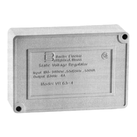
Basler VR63-4B User manual

Basler

Basler VR63-4B User manual

Basler AVC63-12A1 User manual

Basler

Basler AVC63-12A1 User manual

Basler SCP 250 User manual

Basler

Basler SCP 250 User manual

Basler APR 63-5 User manual

Basler

Basler APR 63-5 User manual

Basler SSR 32-12 User manual

Basler

Basler SSR 32-12 User manual

Basler AVC63-4 User manual

Basler

Basler AVC63-4 User manual

Basler AVC63-12 User manual

Basler

Basler AVC63-12 User manual

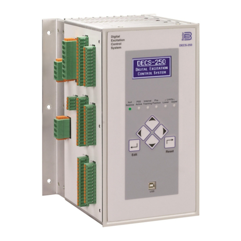
Basler DECS-250 User manual

Basler

Basler DECS-250 User manual

Basler KR4FFX User manual

Basler

Basler KR4FFX User manual

Basler AVC63-4A User manual

Basler

Basler AVC63-4A User manual

Basler DGC-500 User manual

Basler

Basler DGC-500 User manual

Basler BE2000E User manual

Basler

Basler BE2000E User manual

Basler DECS-200 User manual

Basler

Basler DECS-200 User manual

Basler VR63-4A/UL User manual

Basler

Basler VR63-4A/UL User manual

Basler DGC-2020 User manual

Basler

Basler DGC-2020 User manual

Basler AVC63-4A User manual

Basler

Basler AVC63-4A User manual

Basler AVC63-2 User manual

Basler

Basler AVC63-2 User manual

Basler DGC-2020ES User manual

Basler

Basler DGC-2020ES User manual

Popular Controllers manuals by other brands

Sunricher SR-ZV9003T3-RGBW-US Installation

Sunricher

Sunricher SR-ZV9003T3-RGBW-US Installation

Ksenia intro Installation and configuration manual

Ksenia

Ksenia intro Installation and configuration manual

Inovance CAN200 Series manual

Inovance

Inovance CAN200 Series manual

Gauzy LC6 FLEX Controller Installation and operation guide

Gauzy

Gauzy LC6 FLEX Controller Installation and operation guide

Viking SLP-1 Technical practice

Viking

Viking SLP-1 Technical practice

CKD KBX-30E-U Series instruction manual

CKD

CKD KBX-30E-U Series instruction manual

Sharp Energy Sun Flux User manual & installation guide

Sharp Energy

Sharp Energy Sun Flux User manual & installation guide

Yamaha RCX40 user manual

Yamaha

Yamaha RCX40 user manual

AB Quality PowerFlex 400 Frames D-H Service bulletin

AB Quality

AB Quality PowerFlex 400 Frames D-H Service bulletin

Yamaha MJC8 owner's manual

Yamaha

Yamaha MJC8 owner's manual

AL-KO ATC operating instructions

AL-KO

AL-KO ATC operating instructions

Savant SmartControl 2 Deployment guide

Savant

Savant SmartControl 2 Deployment guide

GameSir T3S user manual

GameSir

GameSir T3S user manual

Kostal inveor operating manual

Kostal

Kostal inveor operating manual

Emerson Yarway 20-55 Operating and safety instructions

Emerson

Emerson Yarway 20-55 Operating and safety instructions

CoCo ACM-LV24 Quick installation guide

CoCo

CoCo ACM-LV24 Quick installation guide

Brooks SLA5810/20 Installation and operation manual

Brooks

Brooks SLA5810/20 Installation and operation manual

SIGMA TEK SR 011 Technical manual

SIGMA TEK

SIGMA TEK SR 011 Technical manual

manuals.online logo
manuals.online logoBrands
  • About & Mission
  • Contact us
  • Privacy Policy
  • Terms and Conditions

Copyright 2025 Manuals.Online. All Rights Reserved.

BASLER ELECTRIC, BOX 269, HIGHLAND, IL 62249 PHONE 618/654-2341 FAX 618/654-2351
INTRODUCTION
The AVC63-2.5 Voltage Regulators are
designed for use on 50/60 Hz brushless
generators. The regulator includes frequency
compensation, a solid-state build-up circuit,
EMI filtering, and remote adjust capability.
Warning
To prevent personal injury or equipment
damage, only qualified technicians or
operators should install, operate, or
service this device.
ELECTRICAL SPECIFICATIONS
Dc Output Power:
2.5 Adc at 63 Vdc (157.5W) maximum
continuous,
3.97 Adc at 100 Vdc (397W) forcing one
minute
(at 240 Vac input).
Exciter Field Dc Resistance:
25.2 ohms minimum.
Ac Power Input:
Operating range: 171 to 264 Vac, +10%,
Single phase, 50/60 Hz, Burden: 350 VA.
Sensing Input:
171-264 Vac, +10%, Single phase, 50/60 Hz,
Burden: 350 VA.
Regulation Accuracy:
Better than ±1.0% no load to full load.
EMI Suppression:
Internal electromagnetic interference filter
(EMI filter).
Voltage Build-up:
Internal provisions for automatic voltage build-
up from generator residual voltages as low as
10 Vac.
Terminations:
1/4 inch "Fast-On" terminals.
PHYSICAL SPECIFICATIONS
Operating Temperature:
-40°C (-40°F) to +60°C (+140°F).
Storage Temperature:
-40°C (-40°F) to +85°C (+185°F).
Vibration:
Withstands 1.5 Gs at 5 to 29 Hz; 0.036"
double amplitude at 29 to 52 Hz; and 5 Gs at
52 to 500 Hz.
Shock:
Withstands up to 15 Gs in each of three
mutually perpendicular axes.
Weight:
3.8 oz. (0.107 kg) Net.
FUSES
It is recommended that fuses with high
interruption capability be installed per the
interconnection diagram to protect wiring from
faults before the regulator. Refer to the
Interconnection Drawings.
NOTE
Fuse must be installed per the
interconnection diagrams to avoid inter-
rupting the field current.
AVC63-2.5 Outline Diagram (Top View)
AVC63-2.5 Outline Diagram (Side View)
V/HZ "CORNER FREQUENCY" SELECTION
AND ADJUSTMENT
The corner frequency can be adjusted by the
UF ADJ rheostat on the AVR. Clockwise
rotation results in raising the corner frequency
(shifting the curve to the right). To set the UF
rheostat:
1. Adjust the UF Rheostat fully CCW.
2. Start the generator and set at rated voltage.
3. Adjust the generator frequency to the
desired kneepoint frequency.
4. Slowly adjust the UF ADJ rheostat
clockwise (CW) until the generator voltage
just begins to decrease.
Typical Frequency Compensation Curves
OPERATION
The following system operation procedures
provide instructions for adjusting the AVC63-
2.5 voltage regulator. Symptoms resulting
from a faulty regulator and certain generator
system problems are included, together with
suggested remedies.
Complete the following steps before
proceeding with the system start-up.
CAUTION
Meggers and high potential test
equipment must not be used. Incorrect
use of such equipment could damage the
semiconductors contained in the
regulator.
PRELIMINARY SET-UP
1. Verify that the voltage regulator
specifications conform with the generator
system requirements.
2. Ensure the voltage regulator is correctly
connected to the generator system.
3. Install the fuses as described in Fuses.
4. Set the regulator VOLT ADJ and
external VOLT ADJ (if used) as follows:
Regulator VOLT ADJ:Fully CCW
Remote VOLT ADJ:Centered
SYSTEM START-UP
1. Perform preliminary set-up as described
in the above paragraphs.
NOTE
All voltage readings are to be taken with
an average reading voltmeter.
2. Start prime mover and bring up to rated
speed.
RESULT: Voltage should build up. If not,
perform Field Flashing.
3. Slowly adjust the regulator VOLT ADJ CW
until the generator output voltage reaches
the nominal value. If used, adjust the
remote VOLT ADJ to set the generator
voltage to the exact value desired.
RESULT: Voltage should build up to rated
value. If voltage does not build up to rated
value, check generator for short or excessive
load.
CONFIDENTIAL INFORMATION
OF BASLER ELECTRIC COMPANY, HIGHLAND, IL.
IT IS LOANED FOR CONFIDENTIAL USE, SUBJECT
TO RETURN ON REQUEST, AND WITH THE
MUTUAL UNDERSTANDING THAT IT WILL NOT BE
USED IN ANY MANNER DETRIMENTAL TO THE
INTEREST OF BASLER ELECTRIC COMPANY.
Publication:
9 3183 00 991
© 1998, Basler Electric Co., Highland, IL 62249
First Printing January 1998
Revision: A March 1998
INSTRUCTION MANUAL
FOR
VOLTAGE REGULATOR
Model: AVC63-2.5
Part Number: 9 3183 00 101
4. Check regulator under normal operating
and loading conditions.
RESULT: Voltage regulation should be better
than ±1.0% no-load to full-load. If regulation
is not within this range, perform the following
steps:
1. Voltage reduction under load may be due to
speed change from no load to full load,
causing the frequency compensation (V/Hz)
circuit to reduce voltage at lower
frequencies.
2. Replace voltage regulator.
OPERATIONAL TEST
1. Connect the test setup as shown in the
following figure, Operational Test. Do not
apply power. Ensure that the light bulb is
rated for 120 V and is less than 100 W.
2. Adjust the regulator VOLT ADJ and/or
remote VOLT ADJ to maximum CW.
3. Apply 240 V, 50/60 Hz power to the
regulator. The light bulb should illuminate.
4. Slowly adjust the regulator VOLT ADJ
control CCW. At the regulation point, the light
bulb should extinquish.
The following notes (∆) apply to the intercon-
nection diagrams:
1. If external pot is not used, short terminals 6
and 7.
2. Item not supplied by Basler Electric.
3. Select fuses with high interrupting capacity.
4. Excitation On/Off Switch (If Used).
Operational Test
Interconnection Diagram, 277/480 V Nominal, 3-Phase, 4-Wire, Wye
Connection
Interconnection Diagram, 120/240 V Nominal, 1-Phase, 3-Wire
Interconnection Diagram, 120/208 V Nominal, 3-Phase, 4-Wire, Wye
Connection
Potentiometer and Connector Locations