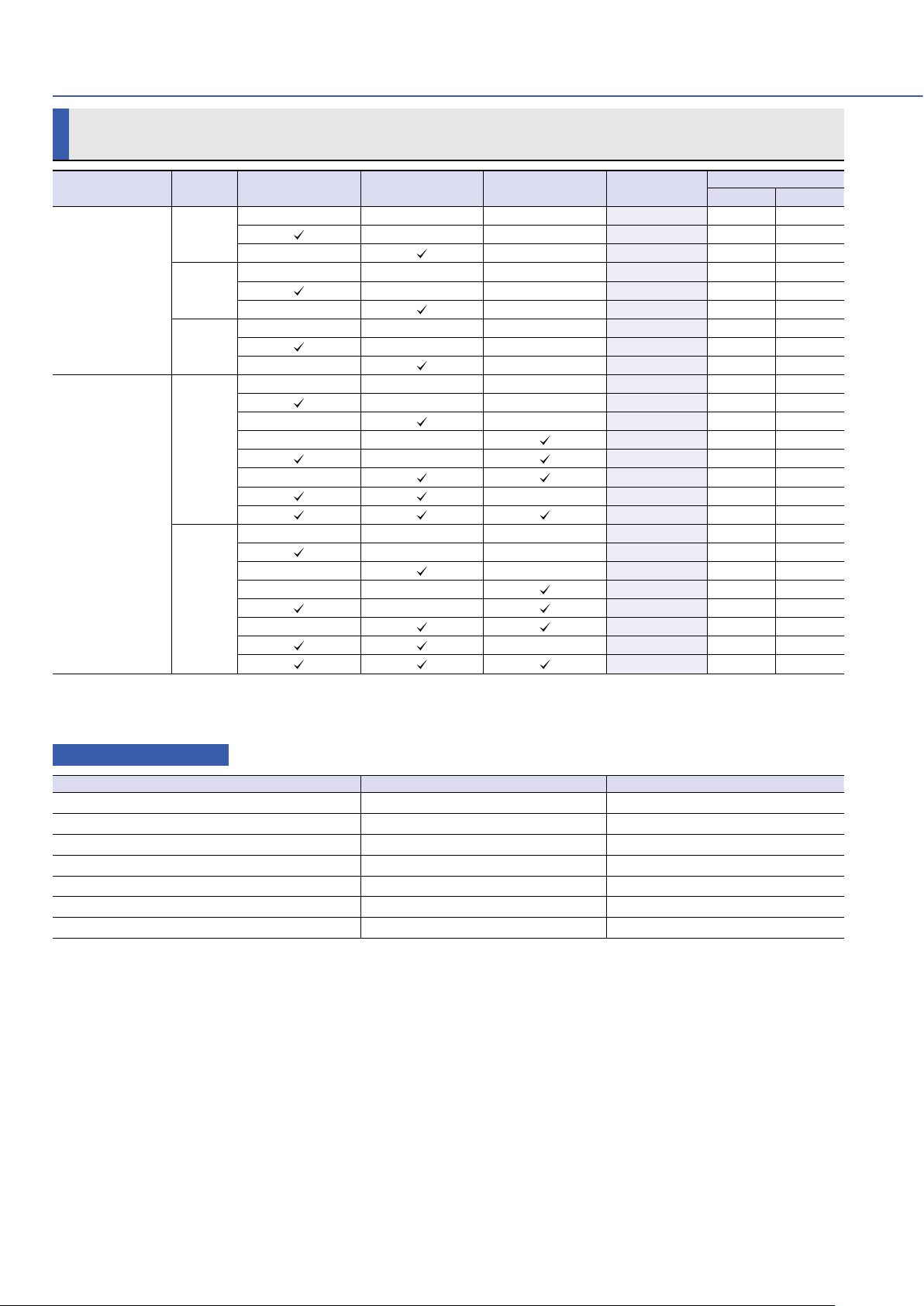
Sanyo Denki SANMOTION K User manual

DC Servo Systems
DC SERVO SYSTEMS
Ver.1.2

Contents
Servo motor
42, 54, 76, 88 mm
23 to 500 W
Input voltage 24 VDC, 75 VDC
Rated output
Features.........................................................p. 4
System Configuration Example ...p. 5
How to Read Model Numbers.......p. 7
Standard Model Number List ........p. 8
Specifications ......................................... p. 10
Common Specifications.................. p. 14
Encoder Specifications .................... p. 15
Dimensions .............................................. p. 16
Selection Guide..................................... p. 24
Safety Precautions.............................. p. 25
DC
Flange size

3
Contents
Servo motor
42, 54, 76, 88 mm
23 to 500 W
Input voltage 24 VDC, 75 VDC
Rated output
Features.........................................................p. 4
System Configuration Example ...p. 5
How to Read Model Numbers.......p. 7
Standard Model Number List ........p. 8
Specifications ......................................... p. 10
Common Specifications.................. p. 14
Encoder Specifications .................... p. 15
Dimensions .............................................. p. 16
Selection Guide..................................... p. 24
Safety Precautions.............................. p. 25
DC
Flange size

Cogging torque has been reduced by up to half compared with our
conventional DC servo motors.* This enables smooth motor operation
even at low speeds, improving the accuracy of equipment movements.
In addition to 75 VDC class models, low-voltage (24 VDC class)
models are also available. The low-voltage models are safe for
use in medical equipment and other applications close to people.
Power loss has been reduced by up to approximately 30% and efficiency has
been increased by 10% compared with our conventional DC servo motors.* This
reduces heat generation within equipment and contributes to energy savings.
Brush vibrations have been reduced, and the rigidity of motor
parts has been improved. Compared with our conventional DC
servo motors,* noise levels have been reduced by up to 8 dB.
High accuracy (Smooth operation)
All servo motors have a protection rating of IP43.
IP43 protection rating →page 14
Low noise
Low-voltage models available
Energy-saving (High efficiency)
* Compared with our conventional SANMOTION T DC servo motors.
Loss
Conventional
motor
K motor
Speed
Noise level
Conventional
motor
K motor
8
dB
Max.
reduction
Comparison of cogging torque waveforms
(Image for illustrative purpose only)
K motor
Conventional
motor
Max.
1/2
reduction
Max.
30
%
reduction
4
Features
The SANMOTION K DC servo motors achieve smooth
operation
,
high efficiency
,
and low noise.These motors are
suitable for applications requiring high precision
,
including
precision measuring instruments and medical equipment.

Cogging torque has been reduced by up to half compared with our
conventional DC servo motors.* This enables smooth motor operation
even at low speeds, improving the accuracy of equipment movements.
In addition to 75 VDC class models, low-voltage (24 VDC class)
models are also available. The low-voltage models are safe for
use in medical equipment and other applications close to people.
Power loss has been reduced by up to approximately 30% and efficiency has
been increased by 10% compared with our conventional DC servo motors.* This
reduces heat generation within equipment and contributes to energy savings.
Brush vibrations have been reduced, and the rigidity of motor
parts has been improved. Compared with our conventional DC
servo motors,* noise levels have been reduced by up to 8 dB.
High accuracy (Smooth operation)
All servo motors have a protection rating of IP43.
IP43 protection rating →page 14
Low noise
Low-voltage models available
Energy-saving (High efficiency)
* Compared with our conventional SANMOTION T DC servo motors.
Loss
Conventional
motor
K motor
Speed
Noise level
Conventional
motor
K motor
8
dB
Max.
reduction
Comparison of cogging torque waveforms
(Image for illustrative purpose only)
K motor
Conventional
motor
Max.
1/2
reduction
Max.
30
%
reduction
5
System Configuration Example
Brake power
Servo motor
Control power
Main circuit power supply
100 VAC
50/60 Hz
140 VDC power supply
Electromagnetic contactor
Molded case circuit breaker
(MCCB)
Noise filter
Amplifier
アンプが必要な場合は当社までご相談ください。
Host controller
Contact us if you need an amplifier.

7
Flange size
Input voltage
K series
K A 30 B S0
Incremental encoder
Holding brake / Tachogenerator
Rated output
Xー
BrakeCode
-
C 24 VDC
B 90 VDC Standard
Options
Standard
Options
D 48 VDC
Tー
H 24 VDC
J 90 VDC
K 48 VDC
Tachogenerator Remarks
02 23 W
Specifications
RemarksCode
06 60 W
04 40 W
08 80 W
11 80 W For 24 VDC input voltage
110 W
30 300 W
20 200 W
40 400 W
50 500 W
For 75 VDC input voltage
442 mm sq.
Specifications
Code
776 mm sq.
554 mm sq.
888 mm sq.
S0 2000
XX ー ー
Pulses per revolution
Code Remarks
Line driver
S7 500
S6 200
Standard
Options
S8 1000
C0 2000
Open collector
C7 500
C6 200
C8 1000
Output circuit
A
Code Input voltage Remarks
Only for 42 and 54 mm sizesB 24 VDC class
75 VDC class
6

7
Flange size
Input voltage
K series
K A 30 B S0
Incremental encoder
Holding brake / Tachogenerator
Rated output
Xー
BrakeCode
-
C 24 VDC
B 90 VDC Standard
Options
Standard
Options
D 48 VDC
Tー
H 24 VDC
J 90 VDC
K 48 VDC
Tachogenerator Remarks
02 23 W
Specifications
RemarksCode
06 60 W
04 40 W
08 80 W
11 80 W For 24 VDC input voltage
110 W
30 300 W
20 200 W
40 400 W
50 500 W
For 75 VDC input voltage
442 mm sq.
Specifications
Code
776 mm sq.
554 mm sq.
888 mm sq.
S0 2000
XX ー ー
Pulses per revolution
Code Remarks
Line driver
S7 500
S6 200
Standard
Options
S8 1000
C0 2000
Open collector
C7 500
C6 200
C8 1000
Output circuit
A
Code Input voltage Remarks
Only for 42 and 54 mm sizes
B 24 VDC class
75 VDC class
7
■
How to read model numbers
Not all combinations of descriptions below are valid.
For model numbers valid as standard products, refer to“Standard Model Number List.”
Low Cogging Torque, Low Loss,
Low Noise
Output capacity: 23 to 500 W
For 42 and 54 mm motors, low-voltage (24 VDC) models are also
available.
Servo motor

8
Flange size Rated
output Encoder Tachogenerator Holding brake
(90 VDC) Model no. Page
Specifications
Dimensions
42 mm sq.
23 W
ーーーKB402XXX p. 10 p. 16
ー ー KB402XS0 p. 10 p. 17
ー ー KB402TXX p. 10 p. 18
40 W
ーーーKB404XXX p. 10 p. 16
ー ー KB404XS0 p. 10 p. 17
ー ー KB404TXX p. 10 p. 18
60 W
ーーーKB406XXX p. 10 p. 16
ー ー KB406XS0 p. 10 p. 17
ー ー KB406TXX p. 10 p. 18
54 mm sq.
60 W
ーーーKB506XXX p. 11 p. 16
ー ー KB506XS0 p. 11 p. 17
ー ー KB506TXX p. 11 p. 18
ー ー KB506BXX p. 11 p. 19
ーKB506BS0 p. 11 p. 20
ーKB506JXX p. 11 p. 21
ーKB506TS0 p. 11 p. 22
KB506JS0 p. 11 p. 23
80 W
ーーーKB511XXX p. 11 p. 16
ー ー KB511XS0 p. 11 p. 17
ー ー KB511TXX p. 11 p. 18
ー ー KB511BXX p. 11 p. 19
ーKB511BS0 p. 11 p. 20
ーKB511JXX p. 11 p. 21
ーKB511TS0 p. 11 p. 22
KB511JS0 p. 11 p. 23
Standard Model Number List
Input voltage
24 VDC class (Low-voltage model)
■Options
Brush (Maintenance parts)
Applicable product Model no. Quantity
For 42 mm sq. motors AL-01027427 2 pcs
For 54 mm sq. motors AL-01027428 2 pcs (60 W, 110 W), 4 pcs (80 W)
For 76 mm sq. motors AL-01027429 4 pcs
For 88 mm sq. motors AL-01027430 4 pcs
For 42 mm sq. tachogenerators S813053-1A-87 2 pcs
For 54 mm sq. tachogenerators S782281-1A-87 2 pcs
For 76 and 88 mm sq. tachogenerators S782279-1A-87 2 pcs

Standard Model Number List
9
Flange size Rated
output Encoder Tachogenerator Holding brake
(90 VDC) Model no. Page
Specifications
Dimensions
42 mm sq.
40 W
ーーーKA404XXX p. 12 p. 16
ー ー KA404XS0 p. 12 p. 17
ー ー KA404TXX p. 12 p. 18
60 W
ーーーKA406XXX p. 12 p. 16
ー ー KA406XS0 p. 12 p. 17
ー ー KA406TXX p. 12 p. 18
54 mm sq.
60 W
ーーーKA506XXX p. 12 p. 16
ー ー KA506XS0 p. 12 p. 17
ー ー KA506TXX p. 12 p. 18
ー ー KA506BXX p. 12 p. 19
ーKA506BS0 p. 12 p. 20
ーKA506JXX p. 12 p. 21
ーKA506TS0 p. 12 p. 22
KA506JS0 p. 12 p. 23
110 W
ーーーKA511XXX p. 12 p. 16
ー ー KA511XS0 p. 12 p. 17
ー ー KA511TXX p. 12 p. 18
ー ー KA511BXX p. 12 p. 19
ーKA511BS0 p. 12 p. 20
ーKA511JXX p. 12 p. 21
ーKA511TS0 p. 12 p. 22
KA511JS0 p. 12 p. 23
76 mm sq.
200 W
ーーーKA720XXX p. 13 p. 16
ー ー KA720XS0 p. 13 p. 17
ー ー KA720TXX p. 13 p. 18
ー ー KA720BXX p. 13 p. 19
ーKA720BS0 p. 13 p. 20
ーKA720JXX p. 13 p. 21
ーKA720TS0 p. 13 p. 22
KA720JS0 p. 13 p. 23
300 W
ーーーKA730XXX p. 13 p. 16
ー ー KA730XS0 p. 13 p. 17
ー ー KA730TXX p. 13 p. 18
ー ー KA730BXX p. 13 p. 19
ーKA730BS0 p. 13 p. 20
ーKA730JXX p. 13 p. 21
ーKA730TS0 p. 13 p. 22
KA730JS0 p. 13 p. 23
88 mm sq.
400 W
ーーーKA840XXX p. 13 p. 16
ー ー KA840XS0 p. 13 p. 17
ー ー KA840TXX p. 13 p. 18
ー ー KA840BXX p. 13 p. 19
ーKA840BS0 p. 13 p. 20
ーKA840JXX p. 13 p. 21
ーKA840TS0 p. 13 p. 22
KA840JS0 p. 13 p. 23
500 W
ーーーKA850XXX p. 13 p. 16
ー ー KA850XS0 p. 13 p. 17
ー ー KA850TXX p. 13 p. 18
ー ー KA850BXX p. 13 p. 19
ーKA850BS0 p. 13 p. 20
ーKA850JXX p. 13 p. 21
ーKA850TS0 p. 13 p. 22
KA850JS0 p. 13 p. 23
Input voltage
75 VDC class

10
Specifications
Servo motor model no. Inside
《
》
indicates motor flange size
KB402
《42 mm sq.》
KB404
《42 mm sq.》
KB406
《42 mm sq.》
Condition
Symbol
Unit
Rated output ☆☆ PRW 23 40 60
Rated armature voltage ☆☆ VRV 20 24 24
Rated torque ☆☆ TRN
・
m 0.074 0.13 0.19
Rated armature current ☆☆ IRA 1.8 2.7 4.1
Rated speed ☆☆ NRmin-1 3000 3000 3000
Continuous stall torque ☆☆ TSN
・
m 0.08 0.14 0.20
Peak stall torque ☆☆ TP(N) N
・
m 0.42 0.76 1.2
Armature stall current ☆☆ ISA 1.8 2.7 4.1
Peak armature stall current
☆☆ IP(N) A 10 14 23
Maximum speed Nmax min-1 5000 5000 5000
Rated power rate ☆☆ QRkW/s 1.2 2.0 3.3
Torque constant ☆KTN
・
m/A 0.047 0.057 0.056
Voltage constant ☆KE×10-3V/min-1 4.9 6.0 5.9
Rotor inertia JM×10-4kg
・
m20.047 0.084 0.108
Armature winding resistance
☆Ra Ω 3.2 1.7 0.94
Armature inductance ☆La mH 0.9 0.7 0.5
Mechanical time constant ☆tm ms 6.9 4.4 3.2
Electrical time constant ☆te ms 0.28 0.41 0.53
Coefficient of voltage generated
☆KEG V/min-1 3×10⁻³±10%
Effective (rms) ripple ☆ε
s% 2
Peak-to-peak ripple ☆ε
s% 5
Linearity ☆δL% 1
Armature winding resistance
☆R1Ω 37
Armature inductance ☆L1mH 5
Minimum load resistance ☆RLkΩ 10
Rotor inertia JTG ×10-4kg
・
m20.011
Voltage ☆VBV––––
Current ☆IBA––––
Holding torque ☆☆ TBN
・
m––––
Inertia JB×10-4kg
・
m2––––
Resistance ☆RBΩ––––
Mass See the Dimensions section
Size of aluminum plates for heat dissipation during measurement
250 ×250 ×6 mm
Pulses per revolution for encoder
Line driver Standard: 2000 P/ROptional: 200,500,1000 P/R
Open collector Optional: 200,500,1000,2000 P/R
Oil seal ––––
■
Speed-Torque Characteristics
Servo motor model no. / Flange size / Rated output
KB402/42 mm/23 W KB404/42 mm/40 W KB406/42 mm/60 W
0
0.1
0.2
0.3
0.4
0.5
0.6
0
2000 3000 4000 500
0
1000
Speed [min
-1
]
Torque [N・m]
Intermittent duty zone
V=20V
Continuous duty zone
0
0.2
0.4
0.8
0
2000 3000 4000 500
0
1000
0.6
Speed [min
-1
]
Torque [N・m]
Intermittent duty zone
Continuous duty zone
V=24V
0
0.5
1
1.5
0
2000 3000 4000 50001000
Speed [min
-1
]
Torque [N・m]
Intermittent duty zone
V=24V
Continuous duty zone
Input voltage
24 VDC class (Low-voltage model)
MotorTachogeneratorBrake
Encoders can not be installed to KB4 models with a tachogenerator.
The holding brake cannot be used for dynamic braking.
Holding brakes are also available in 24 and 48 V. (Optional)
Specifications are subject to change without notice.
24 VDC class models (low-voltage models) are outside the scope of CE
marking and UKCA marking.
The values in the row with "☆" are for when the ambient temperature and
armature winding temperature are 25°C.
The values in the row with "☆☆" are after thermal equilibrium is established.
The values in the table above are for when operated with a stable DC current
at ambient temperatures below 40°C.
The values for the tachogenerator are for when the test circuit shown below is
used.
10kΩ
10kΩ
0.1μF
TG

11
Specifications
KB506
《54 mm sq.》
KB511
《54 mm sq.》
Servo motor model no. Inside
《
》
indicates motor flange size
Unit
Symbol
Condition
60 80 W PR☆☆ Rated output
24 24 V VR☆☆ Rated armature voltage
0.19 0.26 N
・
m TR☆☆ Rated torque
3.9 5.0 A IR☆☆ Rated armature current
3000 3000 min-1 NR☆☆ Rated speed
0.24 0.32 N
・
m TS☆☆ Continuous stall torque
1.8 2.16 N
・
m TP(N) ☆☆ Peak stall torque
4.5 5.2 A IS☆☆ Armature stall current
31 40 A IP(N) ☆☆
Peak armature stall current
5000 5000 min-1 Nmax Maximum speed
1.6 1.8 kW/s QR☆☆ Rated power rate
0.057 0.06 N
・
m/A KT☆Torque constant
6.0 6.3 ×10⁻³V/min-1 KE☆Voltage constant
0.22 0.37 ×10⁻⁴kg
・
m2JMRotor inertia
1.1 0.44 Ω Ra ☆
Armature winding resistance
0.5 0.3 mH La ☆Armature inductance
7.4 4.5 ms tm ☆Mechanical time constant
0.45 0.61 ms te ☆Electrical time constant
7×10⁻³±10% V/min-1 KEG ☆
Coefficient of voltage generated
1 % ε
s☆Effective (rms) ripple
3 % ε
s☆Peak-to-peak ripple
1 % δL☆Linearity
26 Ω R1☆
Armature winding resistance
4.1 mH L1☆Armature inductance
10 kΩ RL☆Minimum load resistance
0.12 ×10⁻⁴kg
・
m2JTG Rotor inertia
90±10% V VB☆Voltage
0.06 A IB☆Current
0.29 N
・
m TB☆☆ Holding torque
0.01 ×10⁻⁴kg
・
m2JBInertia
1600 Ω RB☆Resistance
See the Dimensions section Mass
305
×305 ×12 mm
Size of aluminum plates for heat dissipation during measurement
Standard: 2000 P/ROptional: 200,500,1000 P/RLine driver
Pulses per revolution for encoder
Optional: 200,500,1000,2000 P/ROpen collector
Can be used Oil seal
■
Speed-Torque Characteristics
Servo motor model no. / Flange size / Rated output
KB506/54 mm/60 W KB511/54 mm/80 W
0
0.5
1
1.5
2
0
2000 3000 4000 500
0
1000
Speed [min
-1
]
Torque [N・m]
Intermittent duty zone
V=24V
Continuous duty zone
0
0.5
1
1.5
2
2.5
0
2000 3000 4000 500
0
1000
Speed [min
-1
]
Torque [N・m]
Intermittent duty zone
V=24V
Continuous duty zone
RoHS
MotorTachogeneratorBrake

12
Specifications
Servo motor model no. Inside
《
》
indicates motor flange size
KA404
《42 mm sq.》
KA406
《42 mm sq.》
KA506
《54 mm sq.》
KA511
《54 mm sq.》
Condition
Symbol
Unit
Rated output ☆☆ PRW 40 60 60 110
Rated armature voltage ☆☆ VRV 72 70 75 75
Rated torque ☆☆ TRN
・
m 0.13 0.19 0.19 0.35
Rated armature current ☆☆ IRA 0.9 1.2 1.1 2.0
Rated speed ☆☆ NRmin-1 3000 3000 3000 3000
Continuous stall torque ☆☆ TSN
・
m 0.14 0.20 0.24 0.42
Peak stall torque ☆☆ TP(N) N
・
m 0.76 1.2 1.8 3.4
Armature stall current ☆☆ ISA 0.9 1.2 1.4 2.1
Peak armature stall current
☆☆ IP(N) A 4.7 7.6 10 18
Maximum speed Nmax min-1 5000 5000 5000 5000
Rated power rate ☆☆ QRkW/s 2.0 3.3 1.6 3.3
Torque constant ☆KTN
・
m/A 0.174 0.177 0.17 0.20
Voltage constant ☆KE×10-3V/min-1 18.2 18.5 17.8 20.8
Rotor inertia JM×10-4kg
・
m20.084 0.108 0.22 0.37
Armature winding resistance
☆Ra Ω 16.8 9.8 9.4 4.8
Armature inductance ☆La mH 7.6 4.5 4.4 3.0
Mechanical time constant ☆tm ms 4.7 3.4 7.2 4.5
Electrical time constant ☆te ms 0.45 0.46 0.47 0.63
Coefficient of voltage generated
☆KEG V/min-1 3×10⁻³±10% 7×10⁻³±10%
Effective (rms) ripple ☆ε
s% 2 1
Peak-to-peak ripple ☆ε
R% 5 3
Linearity ☆δL% 1 1
Armature winding resistance
☆R1Ω 37 26
Armature inductance ☆L1mH 5 4.1
Minimum load resistance ☆RLkΩ 10 10
Rotor inertia JTG ×10-4kg
・
m20.011 0.12
Voltage ☆VBV–––– 90±10%
Current ☆IBA–––– 0.06
Holding torque ☆☆ TBN
・
m–––– 0.29
Inertia JB×10-4kg
・
m2–––– 0.01
Resistance ☆RBΩ–––– 1600
Mass See the Dimensions section
Size of aluminum plates for heat dissipation during measurement
250 ×250 ×6 mm 305 ×305 ×12 mm
Pulses per revolution for encoder
Line driver Standard: 2000 P/ROptional: 200,500,1000 P/R
Open collector Optional: 200,500,1000,2000 P/R
Oil seal –––– Can be used
■
Speed-Torque Characteristics
Servo motor model no. / Flange size / Rated output
KA404/42 mm/40 W KA406/42 mm/60 W KA506/54 mm/60 W K A511/54 mm/110 W
0
0.1
0.2
0.3
0.4
0.7
0.8
0
2000 3000 4000 500
0
1000
Continuous duty zone
0.5
0.6
Intermittent duty zone
V=72V
Speed [min
-1
]
Torque [N・m]
0
0.5
1
1.5
0
2000 3000 4000 50001000
Speed [min
-1
]
Torque [N・m]
Intermittent duty zone
Continuous duty zone
V=70V
0
0.5
1
1.5
2
0
2000 3000 4000 500
0
1000
Speed [min
-1
]
Torque [N・m]
Intermittent duty zone
V=75V
Continuous duty zone
0
0.5
1
1.5
2.5
3
3.5
0
2000 3000 4000 50001000
2
Speed [min
-1
]
Torque [N・m]
Intermittent duty zone
V=75V
Continuous duty zone
Input voltage
75 VDC class
Encoders can not be installed to KB4 models with a tachogenerator.
The holding brake cannot be used for dynamic braking.
Holding brakes are also available in 24 and 48 V. (Optional)
Specifications are subject to change without notice.
The values in the row with "☆" are for when the ambient temperature and
armature winding temperature are 25°C.
The values in the row with "☆☆" are after thermal equilibrium is established.
The values in the table above are for when operated with a stable DC current
at ambient temperatures below 40°C.
The values for the tachogenerator are for when the test circuit shown below is
used.
MotorTachogeneratorBrake
10kΩ
10kΩ
0.1μF
TG

13
Specifications
KA720
《76 mm sq.》
KA730
《76 mm sq.》
KA840
《88 mm sq.》
KA850
《88 mm sq.》
Servo motor model no. Inside
《
》
indicates motor flange size
Unit
Symbol
Condition
200 300 400 500 W PR☆☆ Rated output
80 75 85 80 V VR☆☆ Rated armature voltage
0.64 1.15 1.53 1.91 N
・
m TR☆☆ Rated torque
3.4 4.8 5.7 7.4 A IR☆☆ Rated armature current
3000 2500 2500 2500 min-1 NR☆☆ Rated speed
0.77 1.43 1.70 2.16 N
・
m TS☆☆ Continuous stall torque
5.4 9.8 12 16.7 N
・
m TP(N) ☆☆ Peak stall torque
3.6 5.4 6.0 7.6 A IS☆☆ Armature stall current
25 40 40 62 A IP(N) ☆☆
Peak armature stall current
5000 4000 4000 3000 min-1 Nmax Maximum speed
2.8 4.9 4.7 6.1 kW/s QR☆☆ Rated power rate
0.23 0.27 0.31 0.286 N
・
m/A KT☆Torque constant
24.2 28.6 32.9 30.0 ×10⁻³V/min-1 KE☆Voltage constant
1.47 2.7 5.0 6.0 ×10⁻⁴kg
・
m2JMRotor inertia
2.2 1.05 0.95 0.53 Ω Ra ☆
Armature winding resistance
3.3 1.7 1.5 0.86 mH La ☆Armature inductance
6.1 3.8 4.8 3.9 ms tm ☆Mechanical time constant
1.5 1.6 1.5 1.6 ms te ☆Electrical time constant
7×10⁻³±10% V/min-1 KEG ☆
Coefficient of voltage generated
1 % ε
s☆Effective (rms) ripple
3 % ε
R☆Peak-to-peak ripple
1 % δL☆Linearity
26 Ω R1☆
Armature winding resistance
4.1 mH L1☆Armature inductance
10 kΩ RL☆Minimum load resistance
0.12 ×10⁻⁴kg
・
m2JTG Rotor inertia
90±10% 90±10% V VB☆Voltage
0.11 0.11 A IB☆Current
1.47 1.96 N
・
m TB☆☆ Holding torque
0.09 0.2 ×10⁻⁴kg
・
m2JBInertia
820 820 Ω RB☆Resistance
See the Dimensions section Mass
305
×305 ×12 mm
Size of aluminum plates for heat dissipation during measurement
Standard: 2000 P/ROptional: 200,500,1000 P/RLine driver
Pulses per revolution for encoder
Optional: 200,500,1000,2000 P/ROpen collector
Can be used Oil seal
■
Speed-Torque Characteristics
Servo motor model no. / Flange size / Rated output
KA720/76 mm/200 W KA730/76 mm/300 W KA840/88 mm/400 W KA850/88 mm/500 W
0
2
4
6
0
2000 3000 4000 500
0
1000
Speed [min
-1
]
Torque [N・m]
Intermittent duty zone
V=80V
Continuous duty zone
0
2
4
6
8
10
12
0
2000 3000 40001000
Speed [min
-1
]
Torque [N・m]
Intermittent duty zone
V=75V
Continuous duty zone
0
2
4
8
10
12
14
0
2000 3000 400
0
1000
6
Speed [min
-1
]
Torque [N・m]
V=85V
Intermittent duty zone
Continuous duty zone
0
2
4
8
12
14
18
0
2000 30001000
16
10
6
Speed [min
-1
]
Torque [N・m]
Intermittent duty zone
V=80V
Continuous duty zone
MotorTachogeneratorBrake
RoHS

14
Common Specifications
The protection ratings of our servo motors comply with IEC standards (IEC 60034-5 Edition 4.1,2006-11).
Motor Ground BrakeTachogenerator
(
Red
)(
Red)(Blue
)(
Orange)(Orange
)
(Blue)(Green / Yellow)
■Specifications common to all motors
■Protection rating
■Compliance with International Standards and Directives
■How to connect
Motor rotation direction
When (Red): + and (Blue): -, counterclockwise as viewed from the output axis
Tachogenerator polarity
When rotating counterclockwise as viewed from the output axis, (Red): + and (Blue): -
Protection against solid
objects > 1 mm
Protected against
spraying water
IP-
4 3
4 3
Protection against dust Protection against water
Items Specifications
Rated Continuous (S1)
Thermal class F
Excitation system Permanent magnet
Insulation resistance
10 MΩor more at 500 VDC
Dielectric strength
1500 VAC (600 V for 24 V class and tachogenerator models), for one minute
(However, do not measure dielectric strength between encoder and motor)
Rotation Forward and reverse rotations possible
Ambient temperature
0 to 40°C
Humidity 20 to 90% RH (non-condensing)
Paint color Black
Protection Fully enclosed (IP43)
Lead wire length 1000 mm
Directive Standards
CE marking in Europe
Low Voltage Directive
2014/35/EU
IEC 60034-1, IEC60034-5
Only 75 VDC class models are CE marking-compliant.
24 VDC class models are outside the scope of CE marking.
RoHS Directive 2011/65/EU EN IEC 63000:2018
UKCA marking
in Great Britain
In compliance from July 2022
production onwards.
Electrical Equipment (safety)
Regulaton 2016
IEC 60034-1, IEC60034-5
Only 75 VDC class models are UKCA marking-compliant.
24 VDC class models are outside the scope of UKCA marking.
RoHS Regulations 2012 EN IEC 63000:2018
UL Directive Standards File no.
UL,c-UL UL1004-1,UL1004-6,CSA_C22.2_No.100 E179832(PRHZ2,PRHZ8)
RoHS

15
Encoder Specifications
Items Unit Specifications
Encoder type Incremental encoder
Pulses per revolution P/RStandard: 2000 (Optional: 200,500,1000)
Output circuit Line driver
Number of channels 3
Power supply VDC +5±5%
Current consumption mA 160 max.
Output circuit voltage VDC VOH =2.4 min.,VOL =0.5 max.
at l0 = ±20 mA
Output circuit current mA 20 max.
Response frequency kHz 200
PWM duty cycle T1 = 1/2T0
±1/8T0
Output phase difference T2 to 5= 1/4T0
±1/8T0
Zero-point signal T6 =T0
±0.4T0
Operating temperature °C 0 to +85 (inside the encoder)
Inertia ×10-4kgm20.005
Lead wire color Application
Red +5 VDC
Black GND
(0 V)
Shielded Chassis ground
Blue A-channel output
Brown A-channel output
Green B-channel output
Purple B-channel output
White Z-channel output (zero point)
Yellow Z-channel output (zero point)
■External connection
• Do not exert forces in the axial direction when handling.
• Do not perform insulation resistance or dielectric strength testing as it may damage the electronic circuit.
•The specifications above do not take deviations arising from motor dependencies into account.
*T
0
is the average time for one encoder rotation when the encoder is rotated at a constant speed.
■Output waveform
●Line driver output
(When rotating counterclockwise as viewed from the motor output shaft)
A-channel output
T0*
T1
T2T3T4T5
T6 = T0 ±0.4T0
(One pulse/rotation)
A-channel output
B-channel output
B-channel output
Z-channel output
Z-channel output
Note: An open collector output type is also available as an option.

ØS
ØLB
LR LL
(L1) (L2)
1000±50
ØLH
ØLA
□LC
ØLZ
Motor lead wire
Ground lead wire
LE LG
Q
T
TQK
QKQA
U
T
W
K□4/K□5
(L2)
K□4
K□7/K□8
QK
T
T
MTapped hole
Depth LT
Model No. LL LG L1 L2 LA LB LE LH LC LZ LR
KB402XXX 56±1
5±0.5
40.5
11.5 48±0.2 0
34-0.025 2±0.3 56 42±0.5 4-φ3.5
24±0.8
K□404XXX 69±1 53.5
K□406XXX 82±1 66.5
K□506XXX 81±1 58 17 60±0.3 0
50-0.025 2.5±0.3 69 54±0.5 4-φ4.5
K□511XXX 101±2 78
KA720XXX 100.5±2
8±0.5
74.5 17.5 90±0.3 0
70-0.030
3±0.4
100 76±0.8 4-φ5.5 30±0.8
KA730XXX 124.5±2 98.5
KA840XXX 134±2 103.5 22 100±0.3 0
80-0.030 112 88±0.8 4-φ6.6 35±0.8
KA850XXX 149±2 118.5
Model No. S Q QA QK W T U M LT Mass [kg]
KB402XXX
0
7 -0.009 20±0.5 -15±1.5 Two slots 6.5±0.2 - -
0.30
K□404XXX 0.40
K□406XXX 0.50
K□506XXX 0.70
K□511XXX 0.90
KA720XXX 0
14 -0.011 25±0.5
2
20±0.7
+0.024
5+0.012 50
2-0.2
M5 8 1.80
KA730XXX 2.50
KA840XXX 0
16 -0.011 30±0.5 25±0.7 M6 10 3.40
KA850XXX 4.10
■Servo motor
(Unit: mm)
Dimensions
16

17
1000±50
(L3)
ØS
ØLB
LR LL
(L1) (L2)
1000±50
LE LG
Q
QK
ØLH
ØLA
□LC
T
T
T
TQK
QKQA
U
T
W
K□4/K□5 K□7/K□8
(L3)
(L2)
K□4
MTapped hole
Depth LT
ØLZ
Motor lead wire
Ground lead wire
Encoder lead wire
Model No. LL LG L1 L2 L3 LA LB LE LH LC LZ LR
KB402XS0 83±1
5±0.5
40.5
11.5 9 48±0.2 0
34-0.025 2±0.3 56 42±0.5 4-φ3.5
24±0.8
K□404XS0 96±1 53.5
K□406XS0 109±2 66.5
K□506XS0 110.5±2 58 17 20 60±0.3 0
50-0.025 2.5±0.3 69 54±0.5 4-φ4.5
K□511XS0 130.5±2 78
KA720XS0 134.5±2
8±0.5
74.5 17.5 27 90±0.3 0
70-0.030
3±0.4
100 76±0.8 4-φ5.5 30±0.8
KA730XS0 158.5±2 98.5
KA840XS0 166±2 103.5 22 25 100±0.3 0
80-0.030 112 88±0.8 4-φ6.6 35±0.8
KA850XS0 181±2 118.5
Model No. S Q QA QK W T U M LT Mass [kg]
KB402XS0
0
7 -0.009 20±0.5 -15±1.5 Two slots 6.5±0.2 - -
0.40
K□404XS0 0.55
K□406XS0 0.65
K□506XS0 0.80
K□511XS0 1.10
KA720XS0 0
14 -0.011 25±0.5
2
20±0.7
+0.024
5+0.012 50
2-0.2
M5 8 2.10
KA730XS0 3.10
KA840XS0 0
16 -0.011 30±0.5 25±0.7 M6 10 3.65
KA850XS0 4.25
■Servo motor with encoder
(Unit: mm)
Dimensions

18
Dimensions
■Servo motor with tachogenerator
Model No. LL LG L1 L2 L3 LA LB LE LH LC LZ LR
KB402TXX 85±1
5±0.5
40.5
11.5 23 48±0.2 0
34-0.025 2±0.3 56 42±0.5 4-φ3.5
24±0.8
K□404TXX 98±1 53.5
K□406TXX 111±2 66.5
K□506TXX 124.5±2 58 17 28 60±0.3 0
50-0.025 2.5±0.3 69 54±0.5 4-φ4.5
K□511TXX 144.5±2 78
KA720TXX 148.5±2
8±0.5
74.5 17.5 34 90±0.3 0
70-0.030
3±0.4
100 76±0.8 4-φ5.5 30±0.8
KA730TXX 172.5±2 98.5
KA840TXX 183±2 103.5 22 33 100±0.3 0
80-0.030 112 88±0.8 4-φ6.6 35±0.8
KA850TXX 197.5±2 118.5
Model No. S Q QA QK W T U M LT Mass [kg]
KB402TXX
0
7 -0.009 20±0.5 -15±1.5 Two slots 6.5±0.2 - -
0.34
K□404TXX 0.49
K□406TXX 0.59
K□506TXX 1.00
K□511TXX 1.21
KA720TXX 0
14 -0.011 25±0.5
2
20±0.7
+0.024
5+0.012 50
2-0.2
M5 8 2.15
KA730TXX 2.85
KA840TXX 0
16 -0.011 30±0.5 25±0.7 M6 10 3.85
KA850TXX 4.45
ØS
ØLB
LR LL
(L1) (L2)
1000±50
1000±50
(L3)
Q
LE LG
QK
ØLH
ØLA
□LC
T
T
T
TQK
QKQA
U
T
W
(L2)
K□4/K□5 K□7/K□8
(L3)
K□4
MTapped hole
Depth LT
Tachogenerator lead wire
Motor lead wire
Ground lead wire
ØLZ
(Unit: mm)

19
■Servo motor with holding brake
Model No. LL LG L1 L2 L3 LA LB LE LH LC LZ LR
K□506BXX 118±2 5±0.5 58 17 28.5 60±0.3 0
50-0.025 2.5±0.3 69 54±0.5 4-φ4.5 24±0.8
K□511BXX 138±2 78
KA720BXX 138.5±2
8±0.5
74.5 17.5 30.5 90±0.3 0
70-0.030
3±0.4
100 76±0.8 4-φ5.5 30±0.8
KA730BXX 162.5±2 98.5
KA840BXX 169.5±2 103.5 22 27 100±0.3 0
80-0.030 112 88±0.8 4-φ6.6 35±0.8
KA850BXX 184.5±2 118.5
Model No. S Q QA QK W T U M LT Mass [kg]
K□506BXX 0
7 -0.009 20±0.5 -15±1.5 Two slots 6.5±0.2 - - 0.91
K□511BXX 1.21
KA720BXX 0
14 -0.011 25±0.5
2
20±0.7
+0.024
5+0.012 50
2-0.2
M5 8 2.39
KA730BXX 3.09
KA840BXX 0
16 -0.011 30±0.5 25±0.7 M6 10 4.20
KA850BXX 4.79
ØS
ØLB
LR LL
(L1) (L2)
1000±50
(L3)
1000±50
LE LG
Q
QK
ØLH
ØLA
□LC
T
T
T
TQK
QKQA
U
T
W
K□7/K□8K□5
Motor lead wire
Ground lead wire
Brake lead wire
MTapped hole
Depth LT
ØLZ
(Unit: mm)
Dimensions

20
Dimensions
■Servo motor with encoder and holding brake
Model No. LL LG L1 L2 L3 L4 LA LB LE LH LC LZ
K□506BS0 147±2 5±0.5 58 17 28.5 28 60±0.3 0
50-0.025 2.5±0.3 69 54±0.5 4-φ4.5
K□511BS0 167±2 78
KA720BS0 172.5±2
8±0.5
74.5 17.5 30.5 34.5 90±0.3 0
70-0.030
3±0.4
100 76±0.8 4-φ5.5
KA730BS0 196.5±2 98.5
KA840BS0 203±3 103.5 22 27 35 100±0.3 0
80-0.030 112 88±0.8 4-φ6.6
KA850BS0 218±3 118.5
Model No. LR S Q QA QK W T U M LT Mass [kg]
K□506BS0 24±0.8 0
7 -0.009 20±0.5 -15±1.5 Two slots 6.5±0.2 - - 1.16
K□511BS0 1.46
KA720BS0 30±0.8 0
14 -0.011 25±0.5
2
20±0.7
+0.024
5+0.012 50
2-0.2
M5 8 2.64
KA730BS0 3.44
KA840BS0 35±0.8 0
16 -0.011 30±0.5 25±0.7 M6 10 4.44
KA850BS0 5.04
Motor lead wire
(L3)
ØS
ØLB
LR LL
(L1) (L2)
1000±50
1000±50
1000±50
(L4)
Ground lead wire
Encoder lead wire
Brake lead wire
LE LG
Q
QK
ØLH
ØLA
□LC
ØLZ
T
T
T
TQK
QKQA
U
T
W
K□7/K□8K□5
MTapped hole
Depth LT
(Unit: mm)
This manual suits for next models
9
Table of contents
Other Sanyo Denki Controllers manuals