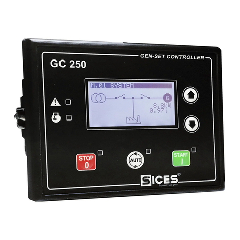
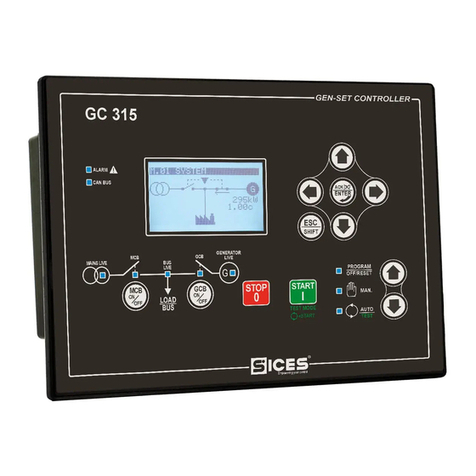
Sices GC250 User manual

Technical Manual
GC250
File name: EAAM057608EN.docx
Rev. 08 Date: 23/05/2019
ID Document: EAAM0576
Product: GC250

ii GC250 Technical Manual EAAM057608EN
Revision
Date
Pages
Notes
00
04/11/2016
140
First version of the manual for the version 01.00 of the
controller.
01
21/11/2016
141
Paragraphs 3, 7.2, 7.3, 9.5.3.2.1, 9.6 modified
02
10/01/2017
141
Modified par. 3 and 7.4.9.2; Added par. 11:10
03
15/06/2017
141
Modified par. 3, Modified Par. 4.1, Modified Par. 5.11
04
25/07/2017
141
Modified table on par. 5 (page 20); Added par. 11:11
05
11/12/2017
141
Modified table on par. 3 (page 16); Modified par. 11:10
06
23/10/2018
138
Modified table 3;
Modified Par. 5.2.1 and 5.2.2
Modified Par. 5.4.1; Modified Par. 5.4.2
07
23/05/2019
143
Modified paragraphs 5.8, 5.6.4, 5.6.3, 5.8.4, 7.4.8.2, 9.1, 10.5,
10.7.48
Added paragraphs 5.8.3, 7.4.8.12 e 7.4.8.13
08
24/10/2019
144
Modified paragraphs 5.6.4, 7.4.7.9, 7.4.8.3, 7.4.8.9, 9.2.3

EAAM057608EN GC250 Technical Manual iii
SOMMARIO
1Introduction.................................................................................................................12
1.1 References.........................................................................................................12
1.2 Information on safety..........................................................................................12
1.3 Introduction and prerequisites ............................................................................13
1.4 Notes on the parameters configuration of the device .........................................13
1.5 Definitions...........................................................................................................13
1.6 Conventions........................................................................................................14
1.7 Software revisions ..............................................................................................14
2Views of the device ....................................................................................................15
3Technical features......................................................................................................16
3.1 Measurement resolution.....................................................................................18
4Installation ..................................................................................................................19
4.1 Mounting.............................................................................................................19
4.2 Wiring .................................................................................................................19
5IN/OUT connections and configuration....................................................................20
5.1 Correspondence input/output and their logic functions.......................................21
5.2 Plant type............................................................................................................22
5.2.1 Principle connection diagram SSB plant ......................................................23
5.2.2 Principle connection diagram SPM plant......................................................24
5.3 T.01 and T.02 Device supply..............................................................................25
5.4 Engine commands outputs T.03 and T.04..........................................................26
5.4.1 T.03 START Command for the engine starter motor....................................26
5.4.2 T.04 FUEL SOLENOID Fuel solenoid command..........................................26
5.5 T.09 D+ Energizing and checking the operation of the recharge alternator........28
5.5.1 T.09 D+ Input used as analogue input..........................................................29
5.5.2 T.09 D+ Input used as analogue input..........................................................29
5.6 T.05.08 Static digital outputs and command loads switching..............................29
5.6.1 Load switching commands SSB plants ........................................................30
5.6.2 Load switching commands SPM plants........................................................31
5.6.3 Digital outputs configuration.........................................................................32
5.6.4 AND/OR logics.............................................................................................35
5.7 Analogue inputs..................................................................................................38
5.7.1 T.13, T.14, T.15 - Resistive analogue inputs................................................38
5.7.2 Configuration and functions of analogue inputs............................................39
5.7.3 Conversion curves........................................................................................42
5.8 Digital inputs.......................................................................................................42
5.8.1 T.16..19 DIGITAL INPUTS...........................................................................43
5.8.2 T.16 D+ Input used as analogue input..........................................................43
5.8.3 Virtual digital inputs ......................................................................................44
5.8.4 Digital inputs configuration ...........................................................................44
5.9 T.22..T.28 Connection to the mains....................................................................48
5.9.1 Measurement of the mains neutral...............................................................48
5.10 T.30..T.36 Connection to generator..............................................................49
5.10.1 Measurement of the generator neutral....................................................49
5.11 T.28..T.40 Current transformer connection...................................................50

iv GC250 Technical Manual EAAM057608EN
6USB Connection.........................................................................................................51
6.1 CAN-BUS connections .......................................................................................52
7Command and indications.........................................................................................53
7.1 Front panel GC250.............................................................................................53
7.2 Push-buttons ......................................................................................................54
7.3 Indicators............................................................................................................55
7.4 Multifunctional display.........................................................................................56
7.4.1 LCD lighting..................................................................................................56
7.4.2 Contrast adjustment .....................................................................................56
7.4.3 Mode navigation...........................................................................................56
7.4.4 Structure of display areas.............................................................................57
7.4.5 Top status bar ..............................................................................................57
7.4.6 Status information (S.xx)..............................................................................58
7.4.7 Electrical measures (M.xx)...........................................................................61
7.4.8 Engine measurements (E.xx).......................................................................64
7.4.9 History logs (H.xx)........................................................................................70
8Parameters programming..........................................................................................77
8.1 Access to programming menu............................................................................77
8.1.1 Menu selection.............................................................................................78
8.2 Parameter organization ......................................................................................78
8.2.1 Parameters selection....................................................................................79
8.2.2 Modify a parameter ......................................................................................79
8.2.3 Set up limits..................................................................................................80
8.3 Exit from programming .......................................................................................80
8.4 Loading default values........................................................................................80
8.5 Protection password...........................................................................................81
8.5.1 Password for commands from serial port (USB) ..........................................82
9Operation sequence...................................................................................................83
9.1 Operating mode..................................................................................................83
9.1.1 Recording of mode in event archive.............................................................85
9.1.2 Operation modes and logics AND/OR..........................................................86
9.2 Mains..................................................................................................................86
9.2.1 Internal sensor..............................................................................................86
9.2.2 External mains sensor..................................................................................89
9.2.3 Mains global status.......................................................................................90
9.2.4 Communication and events..........................................................................91
9.3 Generator ...........................................................................................................91
9.3.1 Genset frequency.........................................................................................91
9.3.2 Genset voltages ...........................................................................................92
9.3.3 Generator status...........................................................................................93
9.3.4 Communication and events..........................................................................94
9.4 Automatic intervention of the generator inhibited................................................94
9.4.1 Inhibition from contact ..................................................................................94
9.4.2 Inhibition from clock......................................................................................95
9.5 Engine ................................................................................................................95
9.5.1 Engine running/stopped status acknowledgement.......................................95
9.5.2 Engine commands........................................................................................96
9.5.3 Command sequence of the engine...............................................................97

EAAM057608EN GC250 Technical Manual v
9.5.4 Communication and events........................................................................100
9.6 Circuit breakers management...........................................................................101
9.6.1 Circuit breakers command..........................................................................101
9.6.2 Acquiring breakers status...........................................................................102
9.6.3 OFF/RESET management logic.................................................................102
9.6.4 Switching logic in AUTO mode...................................................................102
9.6.5 MAN or TEST management logic...............................................................103
9.6.6 Automatic power delivery of the generator inhibited...................................104
9.6.7 Events and signallings related to the breakers...........................................104
10 Anomalies ............................................................................................................105
10.1 Silencing the horn.......................................................................................106
10.2 Acknowledging anomaly.............................................................................106
10.3 Acknowledging anomaly.............................................................................107
10.4 Events and signalling relative to the anomalies..........................................107
10.5 Anomalies connected to digital inputs ........................................................108
10.6 Anomalies connected to analogue inputs...................................................109
10.7 Anomalies list.............................................................................................109
01 –Minimum generator voltage ...........................................................................110
02 –Maximum generator voltage ..........................................................................110
03 –Minimum generator frequency.......................................................................110
04 –Maximum generator frequency......................................................................111
05 –Belt break (alternator battery-charger failure)................................................111
06 –Maximum current...........................................................................................111
07 –Manual stop while in AUTO ...........................................................................113
08 –Operating conditions failure...........................................................................113
13 –Mains circuit breaker (MCB) not closed.........................................................114
14 –Genset circuit breaker (GCB) not closed .......................................................114
16 –Short circuit on the generator.........................................................................114
18 - Overspeed......................................................................................................115
21 –Engine not stopped........................................................................................115
22 –Overcrank......................................................................................................115
23 –Mains circuit breaker (MCB) not open ...........................................................116
24 –Genset circuit breaker (GCB) not open..........................................................116
25 –Minimum fuel level (from contact)..................................................................116
26 –Minimum fuel level (from analogue sensor)...................................................117
27 –Low fuel level (from contact)..........................................................................117
28 –Low fuel level (from analogue sensor)...........................................................117
29 –High fuel level (from contact).........................................................................118
30 –High fuel level (from analogue sensor)..........................................................118
31 –High coolant temperature (from contact) .......................................................118
32 –High coolant temperature (from analogue sensor).........................................119
33 –Maximum coolant temperature (from contact) ...............................................119
34 –Maximum coolant temperature (from analogue sensor) ................................119
35 –Maximum oil temperature (from analogue sensor) ........................................120
37 –Starter battery voltage, low............................................................................120
38 –Starter battery voltage, high...........................................................................120
39 –Service required.............................................................................................121
41 –Minimum oil pressure (from contact)..............................................................121
42 –Minimum oil pressure (from analogue sensor)...............................................122
43 –Low oil pressure (from contact)......................................................................122

vi GC250 Technical Manual EAAM057608EN
44 –Low oil pressure (from analogue sensor).......................................................122
48 –Emergency stop.............................................................................................123
49 –Maximum power ............................................................................................123
52 –Generator voltages unbalance.......................................................................124
53 –Generator current unbalance.........................................................................124
54 –High oil temperature (from analogue sensor).................................................124
55 –Wrong phases sequence...............................................................................125
56 –Low generator voltage ...................................................................................125
57 –Clock not valid ...............................................................................................126
58 –Low generator frequency...............................................................................126
59 –High generator voltage ..................................................................................126
60 –High generator frequency ..............................................................................127
62 –Faulty engine CAN-BUS 0 link.......................................................................127
64 –Fuel pump failure...........................................................................................127
65 –Low coolant temperature (from analogue sensor) .........................................128
98 –Maximum time without CAN-BUS data (engine)............................................128
105 –Battery charger failure from CAN-BUS ........................................................128
118 –Maximum speed from CAN-BUS.................................................................128
132 –High coolant temperature from CAN-BUS ...................................................129
134 –Maximum coolant temperature from CAN-BUS...........................................129
135 –Minimum coolant level from CAN-BUS........................................................129
136 –Low coolant level from CAN BUS ................................................................130
137 –Low battery voltage from CAN BUS.............................................................130
142 –Minimum oil pressure from CAN BUS..........................................................130
144 –Low oil pressure from CAN BUS..................................................................130
158 –High oil temperature from CAN BUS ...........................................................131
159 –Maximum oil temperature from CAN BUS ...................................................131
160 –Water in fuel from CAN BUS........................................................................131
198 –Warnings cumulative –Yellow lamp from CAN-BUS..................................132
199 –Alarms cumulative –Red lamp from CAN-BUS...........................................132
11 Other functions....................................................................................................132
11.1 Fuel pump ..................................................................................................132
11.1.1 Use with an analogue level transducer To use this function: ................133
11.1.2 To use this function requires:................................................................134
11.1.3 Level evaluation....................................................................................134
11.1.4 Automatic pump control ........................................................................134
11.1.5 Manual pump control.............................................................................135
11.1.6 Protections............................................................................................135
11.2 Load thresholds..........................................................................................135
11.2.1 Low load................................................................................................135
11.2.2 High load...............................................................................................136
11.3 Alternative parameters configuration..........................................................136
11.4 EJP function...............................................................................................137
11.5 Maintenance...............................................................................................138
11.5.1 Service hours counter...........................................................................138
11.6 Counters.....................................................................................................138
11.6.1 Counters reset ......................................................................................139
11.7 Clock ..........................................................................................................140
11.7.1 Engine TEST start-up weekly planning.................................................140
11.7.2 Weekly scheduling of engine operating time intervals. .........................140

EAAM057608EN GC250 Technical Manual vii
11.8 Non-volatile memory ..................................................................................141
11.9 Plant name.................................................................................................142
11.10 Power saving mode....................................................................................142
11.11 CAN-BUS connection with engines............................................................143

viii GC250 Technical Manual EAAM057608EN
INDICE
A
AIF.0000 28; 41
AIF.0100 39; 41; 43
AIF.1000 41
AIF.1001 41
AIF.1100 41; 125
AIF.1101 41; 125
AIF.1110 41
AIF.1111 41
AIF.1200 41
AIF.1201 41
AIF.1210 41
AIF.1211 41
AIF.1220 41
AIF.1221 41
AIF.1300 28; 41; 95; 111
AIF.1601 41
AIF.1603 41
AIF.1605 41
AIF.1641 41
D
DIF.0000 43; 44; 45
DIF.1001 45; 103
DIF.1002 45; 103
DIF.1031 45; 103
DIF.1032 45; 103
DIF.2001 45; 107
DIF.2031 45
DIF.2032 45; 85
DIF.2033 45
DIF.2034 45
DIF.2041 45; 103
DIF.2071 45; 69
DIF.2072 45; 69
DIF.2151 45; 136
DIF.2152 45; 137
DIF.2271 46; 83
DIF.2272 46; 83
DIF.2273 46; 83
DIF.2501 43; 46
DIF.2502 46; 104; 137
DIF.2703 46; 135; 136
DIF.3001 46; 102; 114; 116
DIF.3002 46; 102; 114; 116
DIF.3101 46; 86; 89
DIF.3301 46; 134
DIF.3302 46; 134
DIF.4001 44; 46; 108
DIF.4003 46; 108
DIF.4004 46; 108
DIF.4011 46; 108
DIF.4013 46; 108
DIF.4014 47; 108
DIF.4021 47; 109
DIF.4023 47; 109
DIF.4024 47; 109
DIF.4031 47; 109
DIF.4033 47; 109
DIF.4034 47; 109
DIF.4051 47; 109; 135
DIF.4201 43; 47; 108; 123
DIF.4211 47; 116; 134
DIF.4212 47; 117; 134
DIF.4213 47; 118; 134
DIF.4221 47; 96; 121
DIF.4222 47; 96; 122
DIF.4231 47; 118; 119
DIF.4232 47
DOF.0000 33
DOF.0103 33; 35
DOF.1001 33; 97
DOF.1003 26; 33; 97
DOF.1005 26; 33; 97
DOF.1006 30; 33; 97
DOF.1032 33; 127; 133
DOF.1034 33; 133
DOF.1035 33; 69
DOF.1036 33; 69
DOF.2001 33; 101
DOF.2002 33; 101
DOF.2003 33; 101
DOF.2004 30; 33; 101; 116
DOF.2031 33; 102
DOF.2032 33; 102
DOF.2033 33; 102
DOF.2034 30; 32; 33; 102; 103; 116
DOF.3001 33; 85
DOF.3002 33; 85
DOF.3003 33; 85
DOF.3004 33; 85
DOF.3005 33; 85
DOF.3011 33; 85
DOF.3012 33; 86
DOF.3032 33; 94
DOF.3033 33; 91
DOF.3061 33
DOF.3121 33; 135
DOF.3151 33; 107
DOF.3152 30; 33; 105; 107
DOF.3153 33
DOF.4001 33; 107
DOF.4003 33; 107
DOF.4004 33; 107
DOF.4005 33; 107

EAAM057608EN GC250 Technical Manual ix
DOF.4031 33; 107
DOF.4032 34; 107
DOF.4034 35; 107
DOF.4035 35; 108
E
EVT.1001 71; 85
EVT.1002 71; 85
EVT.1003 71; 85
EVT.1004 71; 85
EVT.1005 71; 85
EVT.1010 71; 91
EVT.1011 71; 91
EVT.1012 71; 91
EVT.1013 71; 95
EVT.1014 71; 95
EVT.1020 71; 94
EVT.1021 71; 94
EVT.1022 71; 94
EVT.1030 71; 104
EVT.1031 72; 104
EVT.1032 72; 104
EVT.1033 72; 104
EVT.1035 72; 104
EVT.1036 72; 104
EVT.1037 72; 104
EVT.1038 72; 104
EVT.1040 72; 100
EVT.1041 72; 100
EVT.1042 72; 100
EVT.1043 72; 100
EVT.1044 72; 100
EVT.1050 72; 100
EVT.1051 72; 100
EVT.1052 72; 100
EVT.1053 72; 100
EVT.1054 72; 101
EVT.1055 101
EVT.1056 72; 101
EVT.1057 101
EVT.1058 72; 101
EVT.1059 101
EVT.1062 72; 101
EVT.1070 72
EVT.1071 72
EVT.1074 72
EVT.1075 72
EVT.1076 72
EVT.1077 72
EVT.1078 72
EVT.1079 72
EVT.2000 72
EVT.4000 72
EVT.5000 72
P
P.0000 64; 67; 81; 82
P.0001 63; 64; 67; 81; 82
P.0002 81; 82
P.0003 81; 82
P.0004 82; 84; 85; 97; 99; 103; 104; 106; 107; 123
P.0101 49; 92; 110; 111; 112; 114; 124; 125; 126; 136
P.0102 92; 93; 110; 111; 112; 114; 124; 125; 126; 136
P.0105 86; 87; 91; 110; 111; 115; 126; 127; 136
P.0106 79; 111; 112; 114; 124; 136
P.0107 51; 136
P.0116 86; 87; 88; 89; 90; 136
P.0119 48; 86; 136
P.0125 78; 123; 136
P.0127 64
P.0128 49; 136
P.0129 48; 136
P.0201 86; 87; 88
P.0202 91; 92; 93; 110; 125; 126
P.0203 86; 88
P.0204 87; 88
P.0205 87; 90
P.0206 87
P.0207 94; 95
P.0208 94; 95
P.0209 98
P.0210 97
P.0211 97; 98; 115
P.0212 98
P.0213 100
P.0214 100; 115
P.0215 99; 100
P.0216 46; 47; 108; 118; 119; 120; 121; 122; 123; 124;
125
P.0217 98; 113
P.0218 103
P.0219 31; 103
P.0220 31; 103
P.0222 83
P.0226 92; 93; 96
P.0227 92; 93; 96
P.0228 91; 96
P.0229 91; 92; 96
P.0230 28; 95; 111
P.0231 28; 95; 111
P.0232 96
P.0234 27; 100
P.0236 87
P.0237 87
P.0238 87; 89
P.0239 87; 89
P.0248 103
P.0250 90
P.0271 99
P.0301 92; 93; 110
P.0302 93; 110
P.0303 92; 93; 110
P.0304 93; 110
P.0305 91; 92; 110; 111

xGC250 Technical Manual EAAM057608EN
P.0306 92; 110; 111
P.0307 91; 92; 111
P.0308 92; 111
P.0309 111; 112
P.0310 111; 112
P.0311 114
P.0312 114; 115
P.0315 124
P.0316 124
P.0317 124
P.0318 124
P.0319 125
P.0320 125
P.0323 111; 113; 114; 115
P.0331 115
P.0332 115
P.0335 119
P.0336 119
P.0337 40; 119; 120
P.0338 119; 120
P.0339 122; 123
P.0340 123
P.0341 122
P.0342 122
P.0343 118; 133
P.0344 118
P.0345 117; 133
P.0346 117
P.0347 117; 133
P.0348 117
P.0349 28; 111
P.0350 123
P.0351 123
P.0352 123
P.0353 128
P.0354 128
P.0357 28; 111
P.0362 120
P.0363 120
P.0364 121
P.0365 121
P.0373 124; 125
P.0374 125
P.0375 120
P.0376 120
P.0391 125
P.0392 125
P.0393 126
P.0394 126; 127
P.0395 126
P.0396 126
P.0397 127
P.0398 127
P.0400 132
P.0401 133; 134
P.0402 133
P.0403 133
P.0404 127; 135
P.0405 133
P.0406 133
P.0418 84; 126; 140
P.0419 84; 140
P.0420 84; 126; 140
P.0421 95; 126; 141
P.0422 95; 126; 141
P.0423 95; 126; 141
P.0424 121; 138; 139
P.0425 121; 138
P.0426 85
P.0427 85
P.0428 85
P.0441 71; 85; 91; 94; 95; 100; 104; 142
P.0442 73; 74
P.0443 73; 74
P.0446 69
P.0456 142
P.0479 51
P.0481 135
P.0482 136
P.0483 136
P.0484 136
P.0485 136
P.0486 136
P.0491 106
P.0492 56
P.0493 56
P.0495 54; 97; 99; 113
P.0590 142
P.0599 142
P.0700 52; 65; 66; 75; 96; 119; 120; 122; 123; 125;
127; 128; 129; 130; 131; 132; 143
P.0703 52; 127; 143
P.0704 128; 129; 130; 131; 132
P.0709 127; 128
P.0711 128; 143
P.0802 22; 30; 31; 86
P.2000 44
P.2001 44; 108; 114; 116; 117; 118; 119; 121; 122;
135; 137
P.2002 44; 102; 108; 109; 114; 116; 117; 118; 119;
121; 122; 135; 137; 138
P.2004 137
P.2007 123
P.2008 123
P.2100 44
P.2151 44
P.2152 44
P.3000 32
P.3001 26; 97; 127; 135
P.3002 26
P.4001 29
P.4003 109
P.4004 109
P.4005 109

EAAM057608EN GC250 Technical Manual xi
P.4006 109
P.4007 109
P.4008 109
P.4009 40; 117; 118
P.4011 40
P.4013 40
P.4014 40
P.4015 40
P.4016 40
P.4017 122; 123
P.4025 119; 120; 124; 128
P.4033 43
S
ST_000 36
ST_001 36
ST_002 36
ST_003 36
ST_004 36
ST_006 36
ST_007 36
ST_008 36
ST_010 36
ST_011 36
ST_012 36
ST_014 36
ST_015 36
ST_016 36
ST_017 36
ST_018 36
ST_019 36
ST_020 36
ST_024 36
ST_025 36
ST_026 36
ST_027 36
ST_028 36
ST_032 36
ST_033 36
ST_035 36
ST_036 36
ST_038 36
ST_039 36
ST_040 36
ST_041 36
ST_064 36
ST_065 36
ST_068 36
ST_069 36
ST_070 36
ST_071 36
ST_072 36
ST_073 36
ST_074 36
ST_075 36
ST_080 37
ST_081 37
ST_088 37
ST_090 37
ST_096 37
ST_104 37
ST_112 37
ST_113 37
ST_114 37
ST_128 37
ST_130 37
ST_132 37
ST_133 37
ST_137 37
ST_138 37
ST_256 37
ST_257 37
ST_258 37
ST_259 37
ST_304 37
ST_305 37
ST_306 37
ST_307 37
ST_308 37
ST_320 37
ST_321 37
ST_322 37
ST_323 37
ST_324 37
ST_325 37
ST_326 37
ST_327 37
ST_328 37
ST_329 37
ST_330 37
ST_331 37
ST_332 37
ST_333 37
ST_334 37
ST_335 37
ST_998 37
ST_999 37

12 GC250 Technical Manual EAAM057608EN
1
1.1
[1] SICES EAAM0448xx GC250 parameters chart.
[2] SICES EAAM0458xx - BoardPRG3.xx Manual.
[3] SICES EAAS0449xx GC250 parameters chart.
[4] SICES EAAM0136xx –J1939 Interface Manual.
[5] CANopen –Cabling and Connector Pin Assignment –CiA Draft Recommendation DR-
303-1
[6] BOSCH CAN Specification –Version 2.0 –1991, Robert Bosch Gmbh.
[7] SICES EAAP0457xx USB driver Installation Guide
1.2
Many accidents are caused by poor knowledge and the non-observance of safety regulations,
which must be observed when operating and/or servicing the machine.
To prevent accidents, before using or servicing the machine you should read, understand and
observe the precautions and warnings in this manual.
This manual contains the following indications:
WARNING! This indication is used in the safety messages of the manual when
there are possible danger situations that may cause injuries or death if the danger is
not avoided.
This safety messages describe the normal precautions needed to avoid danger. Ignoring these
precautions can cause serious damage to property and/or injury to persons.
ATTENTION! This indication is used in the safety messages for dangers that, if not
avoided, may cause injuries, damages or malfunctioning.
The message can be also used only for few dangers that may cause damages to things and/or
people.
INFORMATION! This term indicates that the message includes useful information
for the development of the operation or procedures clarifications.

EAAM057608EN GC250 Technical Manual 13
1.3
For the appropriate use of this manual it is required knowledge of the use and of the
installation of generator groups.
WARNING!!!
Every intervention must be carried out by skilled personnel. There are dangerous voltages
on the terminals of the device; before carrying out any operation on them, make sure to open
the mains and genset circuit breakers or to open the related fuses.
Do not remove or change any connection when the genset is running.
Do not disconnect for any reason the terminals of the current transformers (CT)
Wrong operations on the connections can cause the disconnection of the loads from the
mains or the genset.
Please read this manual carefully before using the device.
The device uses a large number of configurable parameters and it is therefore
impossible to describe all their possible combinations and effects.
In this document, there isn’t a detailed description of all the programming parameters: to this
purpose, see documents [1]; these documents are to be considered as part of this manual.
The devices are supplied with a generic “default” configuration; it is at the installer’s
care to adjust the operating parameters to the specific application.
SICES srl carries out a great effort to improve and update its products; therefore, they are
subject to both hardware and software modifications without notice. Some of the features
described in this manual may therefore differ from those present in your device.
1.4
Although most of the parameters and features can be accessed and configured by directly
operating on the device, some particular features or configurations, due to their nature,
can only be set or changed through the PC program SICES Board Programmer3
(hereinafter called “BoardPrg3”), which can be downloaded for free after registration on the
SICES Srl website www.sices.eu www.sices.eu and www.sicesbrasil.com.br/
It simplifies a lot the configuration of the device and its use is strongly suggested. It also allows
you to save the current configuration of the device on a file and to reuse it on other identical
devices,
The program also allows the configuration, saving or loading of the characteristic curves of
non standard analogue sensors with resistive or live output.
BoardPrg3 is usable on every SICES device; the connection to the PC is only possible via
USB serial port; by connecting the USB port to the PC, the device automatically turns on and
it is therefore possible to modify the parameters without other supply sources. For the use of
the program, refer to the document [2].
1.5
In this document, the word “ALARM” is used to indicate a fault that makes the genset
operation impossible and causes the automatic and immediate turning off of the engine with
emergency procedure (without cooling period).

14 GC250 Technical Manual EAAM057608EN
The word “DEACTIVATION” is used to indicate a fault that makes the genset operation
impossible and causes the automatic and immediate turning off of the engine with standard
procedure (with cooling period). The controller immediately opens the GCB circuit breaker
when this kind of fault arises.
The word “WARNING” is used to indicate a fault that requires an operator action but doesn’t
require the automatic shut-down of the genset.
The codes that identify functions for input, output, status or other functions are preceded by
the following acronyms:
DIF (“Digital Input Function”): the following is a code for the configuration of the digital inputs.
DOF (“Digital Output Function”): the following is a code for the configuration of the digital
outputs.
AIF (“ANALOGUE Input Function”): the following is a code for the configuration of the
ANALOGUE inputs.
AOF (“ANALOGUE Output Function”): the following is a code for the configuration of the
ANALOGUE outputs.
AVF (“ANALOGUE Virtual Function”): the following is a code for the configuration of the virtual
ANALOGUE inputs.
EVT (“Event”): the following is an event code
ST (“Status”): the following code shows the status of a dimension or a condition of the device
or of one of its functions.
AL (“Event”): the following is an anomaly code.
1.6
In this manual, the modifications, with respect to the previous version, are signalled by a
vertical bar on the right of the paragraphs. The modifications on the fields of a table are
highlighted with a grey background.
1.7
Several parts of this manual refer to the controller's software revisions. These revisions are
marked with the assigned SICES code (shown on the rear panel of the controller). The format
of the code is: EB0250256XXYY, where “XX” is the main version and “YY” is the minor version.
Thus, the code EB02502560100 refers to the controller software release "1.00". The software
revision is also displayed on page “S.04” of the LCD display.
The software code available at the release date is:
▪EB0250256xxyy GC250.

EAAM057608EN GC250 Technical Manual 15
2
GC250 Front view
Back GC250

16 GC250 Technical Manual EAAM057608EN
3
Supply voltage Vbatt:
7...32VDC with continuous operation, protections intervention at 60
VDC.
Protection against the polarity inversion. Integrated self restoring fuse.
The operation is guaranteed during the engine start up to Vbatt=5VDC
for an undefined time.
The device identifies the plant operation at 12 or 24V to manage its
alarms and for the selection of the excitation current of the generation
of battery charge (signal D+) when powered up and whenever
OFF/RESET mode is selected.
Power consumption in
stand-by
No digital inputs active, engine instruments not connected:
40mA @ Vbatt =13.5VDC display lamp on
26mA @ Vbatt =13.5VDC display lamp off
25mA @ Vbatt =27 VDC display lamp on
16mA @ Vbatt =27 VDC display lamp off
No digital inputs active, engine instruments = 100ohm:
61mA @ Vbatt =13.5VDC display lamp on
47mA @ Vbatt =13.5VDC display lamp off
35mA @ Vbatt =27 VDC display lamp on
28mA @ Vbatt =27 VDC display lamp off
Assorbimento di corrente in
“Deep Stand-by Mode”
<3,4mA @ Vbatt =13.5VDC
<4,3mA @ Vbatt =27 VDC
(Available from HW E611215610001 and FW EB02502560104)
Maximum power consumption
in operating conditions (siren,
LCD lamp, digital inputs active;
communicating CANBUS;
analogue inputs to GND; static
outputs and +D not active)
Max 230mA @ 7 VDC
110mA @ 27 VDC
132mA @ 13.5 VDC
Electric measurements for
mains/generator set voltage
and currents:
ANALOGUE/digital conversion at 12bit; sampling frequency 10kHz.
TRMS
Measurement of the L-N phase voltages and of the L-L concatenated
voltages; measurements of the neutral voltages referred to the power
minus of the power supply of the device.
Input impedance of the voltage measurements:
> 280kohm L-N
> 560kohm L-L
>1600kohm L-GND
>1450kohm N-GND
Measurement of three currents through shunt with electric return and
CT ratio in common.
It is required the use of current transformers with a secondary current
of 5A and minimum power of 1 VA (5VA suggested). It is mandatory to
connect the return poles of the current transformers to the minus of the
power supply of the device.
Amperometric transformers must provide at least one REPEATED
(DOUBLE) insulation for the use of the device in the Overvoltage Cat.
III.
Required connection of the return poles of the amperometric
transformers (T.41) to the negative power supply of the device.

EAAM057608EN GC250 Technical Manual 17
Maximum mains/generator
voltages allowed:
MAX 300Vac in CAT.III for measures L-N
MAX 520Vac in CAT.III for measures L-L
Minimum mains/generator
voltage measurable:
Matching with the minimum voltages required for the frequency
measurement, see below.
Maximum currents allowed:
Continuous 5Aac. Transitory over current measure up to sine wave
20A (< 3s) with progressive loss of precision in measurement.
Maximum transitory over current sine wave 50Aac (<1s).
Frequency measurements:
Rated frequency 50 or 60Hz, measurement from 3 to 99.9Hz
Measurements obtained by the voltage of the L1 phases of
mains/generator.
Minimum sensibility for the minimum mains frequency:
24Vrms L-N @ 60 Hz
Minimum sensibility for the minimum generator frequency:
29Vrms L-N @ 50Hz
32Vrms L-N @ 60Hz
Digital inputs
4 digital inputs with GND supply minus activation. The inversion of the
activation logic from parameter is possible. When open, the voltage on
the input terminals is 4.1V for the input T.16 and 4.6V for the other
three inputs.
Threshold of activation/deactivation 1.55VDC; typical current at close
contact 4mA for T.16 and 4.6mA for the other three inputs.
Maximum voltage applicable: 60VDC
Minimum voltage applicable: -24VDC
The input T.16 can be configured as analogue input for the
measurement of the voltages (see below)
Statics Outputs
Four independent configurable outputs to battery plus, max 500
continuous mA each; internal limitation to approximately 4A max. on
transients <150us and then thermal protection intervention. Protection
against overload, short-circuit and voltage surge and integrated
reverse polarity.
Two independent outputs (T.05 and T.06) used in default for starter
motor and fuel valve, max 10A resistive for 10s, 5A resistive
continuous at 32VDC. Integrated thermal protection, over current, short
circuit and inverse polarity.
Use external opening overvoltage damping diodes, especially for
inductive loads.
For every static output, the outgoing current is supplied through the
positive supply terminal of the T.02 (+BATT) device.
The function of every single output is totally configurable from
parameter.
Excitation output for recharge
alternator +D
Maximum current switched automatically, depending on the supply
voltage Vbatt:
200mA @ 13.5 VDC
100mA @ 27 VDC
If it is not used for the excitation of the battery charger alternator, it is
possible to configure the T.09 terminal as analogue input to acquire
voltage measurements from 0 to 32V or as additional digital input with
+Vbatt activation.
The voltage measurement acquired is displayed in the page S.07 of
the display.

18 GC250 Technical Manual EAAM057608EN
Engine instruments analogue
inputs
Three inputs for resistive sensors plus one input for measuring and
compensation of the reference potential of their common minus.
Resistance measuring range:
range: 0...1kohm with error < 1%
extended: 0 –0...3kohm with error < 2%
The three measurement inputs can also be used as digital inputs with
GND activation, with status change voltage if 1.17VDC
Voltage compensation range of the reference point, with
Rsensors=100ohm:
-2.7...+3.5VDC
Analogue inputs
The input T.16 can be configured from parameter to obtain voltage
signals 0..10VDC referred to GND (T.01)
CANBUS Connection
USB 2.0 for non permanent connection to PC (max 6m) only for the
configuration of parameters with program SICES BoardPrg3.
The device is directly supplied by PC and turns on in OFF/RESET
mode when it is connected, with maximum consumption of 250mA
from USB port.
CANBUS Connection
CanBus connection without galvanic isolation with protocol SAEJ1939
and MTU for the connection to ECU engine control. Fix internal
termination of 120ohm
Display
Graphic transflective LCD, size 65x33mm, resolution 128x64
Self regulating contrast with the temperature and with possibility of
manual correction.
Operating conditions
From -30°C to +70°C, 95% not condensing humidity
Stock conditions
From -35°C to +80°C
Size
141(L)x113(H)x39(P)mm
Weight
191g the only device
250G with connectors and fixing
Dimensions of the mounting
place
118x92mm
Protection degree
IP 65 external with mounted seal, IP20 internal
3.1
Mains/Bars and Genset
voltages
1Vrms
accuracy <1% F.S.
Current
Min. 0.1A (it depends on the CT ratio)
accuracy <1% F.S.
Mains/Bars and Genset
frequencies
0.1Hz ± 50ppm, 35ppm/C typical
Powers
Min. 0.1 kW/kVA/kvar (it depends on the CT ratio)
Power Factor
0.01
Energy
1 kWh/kvarh
Engine speed
1 rpm
Oil pressure
0.1bar (below 10bar)
Cooling liquid temperature
0.1°C
Fuel level
0.1%

EAAM057608EN GC250 Technical Manual 19
4
4.1
The device has to be mounted permanently on a panel. The rear panel of the device must be
accessible only by keys or tools and only by authorized personnel for maintenance operations.
It must be impossible to remove the controller without tools. The electric control panel has to
guarantee an adequate protection against bad weather.
The mounting dimensions for the installation are 118x92mm. The mounting is carried out by
four hooks with screws: once the device is positioned, insert the hooks in the holes on the
sides and tighten the screws. Pay attention not to tighten excessively the screws in order not
to damage the hook on the device.
WARNING !: Operating temperature within the panel may vary between -30 ° C and + 70 ° C;
The outdoor operating temperature (ambient) may vary between -30 ° C and + 60 ° C.
4.2
Due to the high voltages connected to the measurement circuits of the controller, all
conductive parts of the electrical panel should be connected to the protective earthing
through permanent connections.
The installation of an overcurrent protection device is required for each phase of the mains
and generator voltage inputs. You can use 1A fuses.
The section of the protective earthing conductor should be at least equal to the section of
cables used to wire mains or generator voltage to the control panel. In addition, it must comply
with the limit value of the overcurrent protection used.
For CAT.III applications, the maximum phase-to-neutral voltage allowed is 300Vac, while the
phase-to-phase voltage is 520Vac. The maximum voltage related to the protective earthing is
300 Vac.
The device can operate in CAT.III only if the supply minus terminal of the device and the
neutral terminal of the generator are connected to the protective earth.

20 GC250 Technical Manual EAAM057608EN
5
N.
NAME
TERMINAL
FUNCTION
DESCRIPTION
CONNECTOR
1
JA
T.01
GND
Device supply
9 poles x2.5mm
2 screw terminal
T.02
+BATT
T.03
START
Configurable starter engine command
T.04
FUEL
Configurable fuel electro valve
command
T.05
OUT 1
Configurable static outputs at +BATT
T.06
OUT 2
T.07
OUT 3
T.08
OUT 4
T.09
+D, analogue
input 0..32VDC
Output and +D signal detection
/analogue input in configurable voltage
2
JB
T.12
Analogues
reference
Configurable resistor sensors/digital
inputs
10 poles x2.5mm
2 screw terminal
T.13
Fuel level
T.14
Oil pressure
T.15
Cooling liquid
temperature
T.16
Digital input 1,
analogue input
0..10V
Configurable digital inputs
T.17
Digital input 2
T.18
Digital input 3
T.19
Digital input 4
T.20
CAN_H
CANBUS connection and ECU engine
T.21
CAN_L
3
JC
T.22
L3
Mains voltages
4 poles x2.5mm
2 screw terminal
T.24
L2
T.26
L1
T.28
N
4
JD
T.30
L3
Genset voltages
4 poles x2.5mm
Other manuals for GC250
1
Table of contents
Other Sices Controllers manuals
Popular Controllers manuals by other brands

Mankenberg
Mankenberg UV 5.1 ATEX H2 SUPPLEMENT TO THE OPERATING INSTRUCTIONS
IMI
IMI STI RTC Series instruction manual
ESBE
ESBE CRA210 Series manual
Deprag
Deprag AST40-1 Operating instruction booklet
Trio
Trio MC664 Quick connection guide

Stavoklima
Stavoklima DITRONIC User manual, Instructions for Mounting
