7
2. Installation
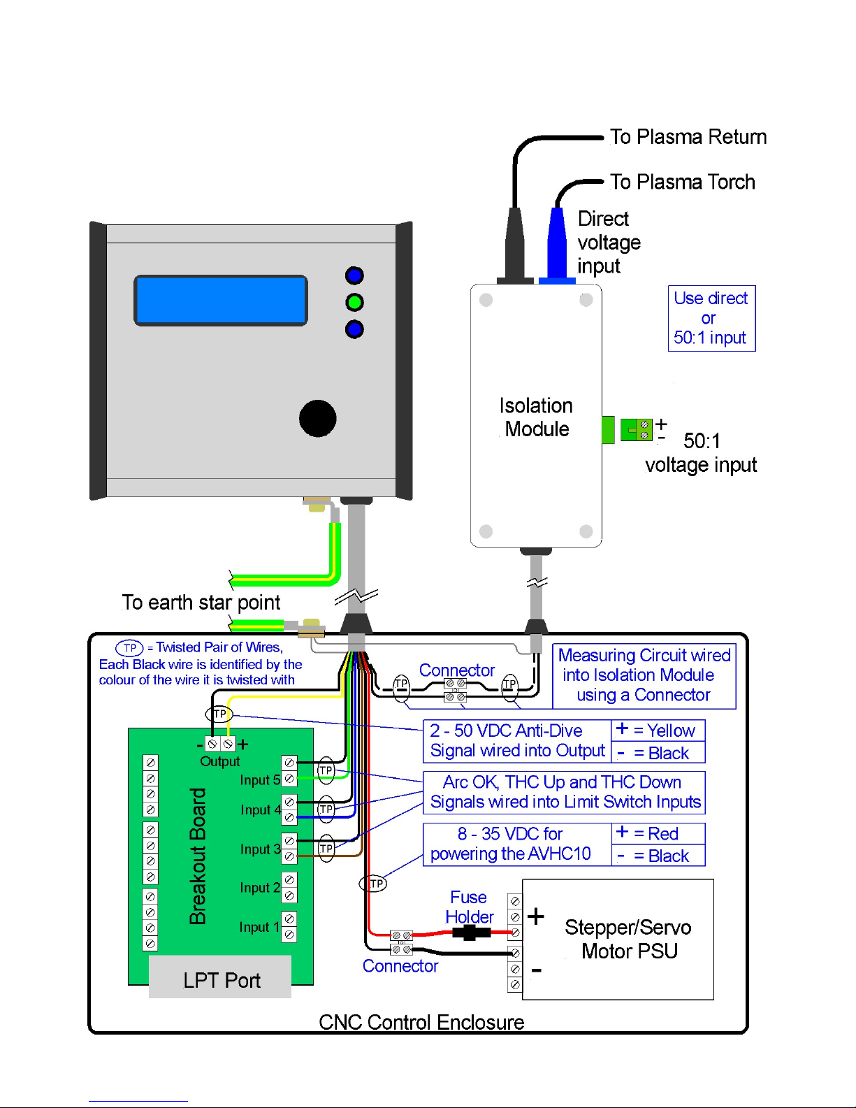
2.1.1 Raw Arc Measuring Point Connections
(We recommend you only use Raw/Direct Arc measurement when the 50:1 voltage divider is
not provided with your plasma cutter. Most good brands of plasma cutter sold for use on
CNC machines will have a 50:1 voltage divider.)
For Raw/Direct Arc measurement, a connection into the main plasma terminals on the
outside of the plasma cutter will usually be sufficient.
Sometimes rust or dirt on the work sheet can cause a poor clamp connection which can
create a voltage difference between the clamp and the work piece which can affect the
measured voltage used for controlling torch height. If you have problems measuring a stable
voltage during cutting, consider connecting the black connection on the Isolation Module to
the work piece by a separate small clamp (this option does not apply to the 50:1 input).
2.1.2 (50:1) Measuring Point Connections
The 50:1 measuring circuit is designed to work with the 50:1 voltage divider output on a
Hypertherm Powermax 45 plasma cutter and other plasma cutters that use the same resistor
network to create the 50:1 voltage. The Hypertherm Powermax 45 plasma cutter uses a
100,000 and a 2,000 ohm resistor in series to produce the 50:1 voltage across the 2,000
ohm resistor. The PriceCNC AVCH10 is calibrated for use with 50:1 voltage dividers with
these particular resistances. Other resistor values may work but the accuracy of the
measured voltage may be affected. Consult your plasma cutter manual to determine if your
plasma cutter has a built in voltage divider and to identify which pins on the connector on the
back of the plasma cutter you need to connect to. Many Hypertherm plasma cutters have
internal dip switches that select the ratio of the internal voltage divider. These may need to
be adjusted to select a 50:1 output voltage.
2.2.1 Anti-Dive input signal on Mach3
A reduced feed rate is often used when cutting small holes or tight angles, this reduced feed
rate will increase the arc voltage, which may cause the AVHC10 to lower the torch into the
work piece. To prevent the torch diving into the work piece when a reduced feed rate is
used, Torch Height Control (THC) should be deactivated during the reduced feed rate. To
temporarily deactivate THC you can use a selection of different methods. An option that is
available in Mach3 is the THC min speed setting which will make the software ignore the
up/down commands from the AVHC10 if the feed rate has dropped by the selected
percentage of the normal (G01) feed rate. This function is usually adequate for good plasma
cutters.
Cheap plasma cutters may need more specific anti-dive assistance by using Cut Rules in
SheetCam that tell the G-code to turn off and on THC as required. These rules are relatively
easy to setup as per section 5. Another way to deactivate Torch Height Control in Mach3 is
to use an anti-dive Macro. Unfortunately Mach3 pauses the operation of the CNC machine
momentarily while it executes the macro which may result in poor cut quality (dings/notches).