Prime Controls DS210 User manual
DS210 Operating Instructions
V5.7 Revision F
2021-11-17

Table of Contents
1Overview................................................................................................................................. 1
2DS210 Installation ................................................................................................................. 1
3DS210 Power Requirements................................................................................................. 1
4DS210 Cable Wiring.............................................................................................................. 2
5DS210 Option Switches......................................................................................................... 4
6DS210 Indicators ................................................................................................................... 5
7DS210 Inputs.......................................................................................................................... 7
8DS210 Outputs....................................................................................................................... 7
9DS210 Calibration................................................................................................................. 9
10 DS210 Compatible Probes and Mounting Brackets......................................................... 10
11 Miscellaneous Functions..................................................................................................... 11
12 DS210 Communications Interface Commands................................................................. 11
13 Specifications ....................................................................................................................... 17
14 Document Revision history................................................................................................. 17
15 LIMITATION AND EXCLUSION OF WARRANTIES................................................ 18

1
1 Overview
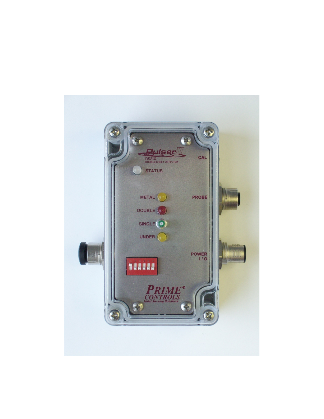
The Model DS210 Double Metal Sheet Detector, together with one of 4 available probes, is designed to
determine a double sheet condition for ferrous metal ranging in thickness from approximately 0.010” to
0.250” (single thickness). The DS210 is housed in a NEMA 4X rated polycarbonate enclosure with a
transparent lid. Connections are made via 12mm industry standard connectors and cord-sets.
The DS210 is a single probe system that uses the magnetic properties of the sample to determine relative
thickness. The DS210 Probe must be in close contact with the sample in order to produce a consistent
result. Since the DS210 does not directly measure sample thickness, it is necessary to perform calibration
from a representative sample.
By connecting the DS210‘s serial port to Prime’s optional serial to EthernetIP gateway, a PLC is able
communicate, control, and monitor the controller. A typical application is to use the communication link to
select previously stored thickness profiles in response to changes in the thicknesses of to be sensed by
the DS210 when using PEXXM (where XX is the probe size: 36, 42, 54, or 75) memory equipped probes.
Please contact Prime Controls for additional information.
This document applies to units with firmware Version 5.7 and later. For earlier versions of firmware, see
earlier versions of the document.
2 DS210 Installation
The DS210 is intended to be installed on a flat surface, using 2 #8 (M4) Pan Head screws. For access to
the mounting holes, remove the cover. Installation is also a convenient time to set the DS210 option
switches (See Section 5).
The location of the DS210 should be within 2m of the probe (Note: this may be extended up to 5m if
necessary). Sufficient clearance should be maintained for the cables / connectors.
3 DS210 Power Requirements
Voltage: 22.5 – 28VDC (24VDC Nominal)
Current: 2A Required Minimum Power Supply
The DS210 operates on 22.5 – 28VDC. With the largest probe, the current requirement is approximately
0.6A RMS, 1.7A peak. The DS210 should be powered with a regulated 24VDC source having a capacity
of 2A. Power should be grounded at the source. DS210 probes can be grounded or floating, as the
application demands.
If the DS210 is to be mounted more that 2m away from the power source, steps should be taken to
ensure that the voltage at the DS210 does not fall below the minimum requirement, especially at the peak
current draw. For example, a standard 15m long M12 cable with 24 gauge (0.25mm2) wire driving the
DS210 requires at least 26.5VDC at the power supply to deliver the minimum input voltage to the DS210
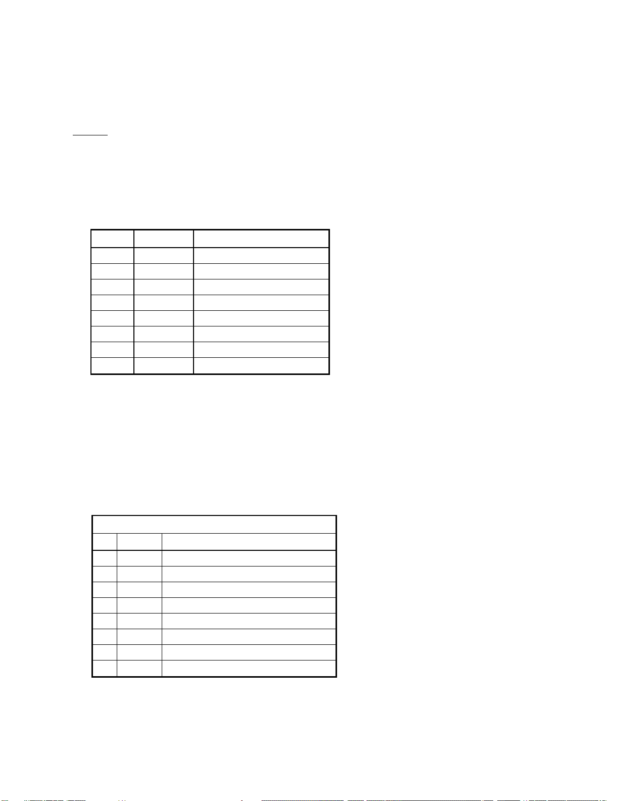
under load. Use the table below for setting your power supply output voltage when using Prime Controls
Power and IO cables:
Cable
Power Supply Voltage
CBL108-2
24VDC
CBL108-5
24VDC
CBL108-15
>26.5VDC
2
4 DS210 Cable Wiring
The DS210 requires two cables for operation. The first is the Power / IO cable. The second is the probe
cable. An RS-232 cable is available if the communications interface is used. A protective plug is provided
to protect the communications interface connector if it is not in use.
Caution:
The DS210 controller is not hot swappable. Power must be turned off when plugging in or unplugging
power or probes to the DS210 controller.
4.1 Power / IO Cable
Prime Controls Cable PN: CBL108-2, -5, or -15. (Dash number indicates length in m.)
The Power / IO cable incorporates 8 conductors whose functions are defined below:
Pin # Wire Color
Function
1
White
24VDC @ 2A
2
Brown
Power Supply Common
3
Green
METAL Output
4
Yellow
NO-DOUBLE Output
5
Gray
UNDER Output
6
Pink
CALIBRATE Input
7
Blue
RESET Input
8 Shield
I/O Common
Table 4.1: Power / IO Cable Wiring
NOTE: The CBL108-15 cable requires at least 26.5VDC at the power supply in order to supply the
minimum 22.5VDC to the DS210 under load.
4.2 Probe Cable
Prime Controls Cable PN: CBL109-2 or -5.
DS210 Probes are connected to the DS210 via a Standard 8-conductor M12 M/F cable. Lengths
beyond 5m may not function properly, and are not recommended.
DS210 / Probe
Pin
Color
Function
1
White
Coil 1
2
Brown
Coil 2
3
Green
Sensor Out
4
Yellow
Proximity Out (Active Low)
5
Gray
+24V
6
Pink
Common
7
Blue
Probe_ID
8
Red
Shield
Table 4.2: Probe Cable Wiring

3
View from Back of Probe
1-White
8-Shield
2-Brown
3-Green 7-Blue
6-Pink
5-Grey
4-Yellow
Figure 4.2: Probe Cable Pin-Out
4.3 RS-232 Communications Cable
Prime Controls Cable PN: CBL210-RS-2, -5, or -15.
The DS210 communications cable consists of a 5-conductor M12 Cable with a female 9-pin D-Sub
connector on the mating end. DATA is sent at 9600 No parity, 8 data bits, 1 stop bit (9600 N81).
Wiring for this cable is shown in Table 4.3 below.
DS210 D-Sub
Pin Color
Function
Pin
Function
1
Brown
N/U
N/U
2
White
TXD
2
RXD
3
Blue
RXD
3
TXD
4
Black
N/U
5
Gray
Signal GND
5
Signal GND
Table 4.3: DS210 Communications Cable Wiring

4
5 DS210 Option Switches
The DS210 incorporates 6 option switches whose functions are as indicated in Table 5.1 below. These
switches are accessible by removing the DS210 cover. Note: Option switch setting changes only take
effect after cycling power to the DS210.
Switch # Position
Function
1
↓(Off)
Continuous sampling OFF
↑(On)
Continuous sampling ON (See switch 2)
2
↓(Off)
Allow continuous sampling (See Switch 1)
↑(On)
Continuous sampling only on DOUBLE (See Switch 1)
3
↓(Off)
Inputs and Outputs emulate PNP. Outputs are open if not
active (off), sourcing ≈24V when active (on). Inputs are
inactive if open, activated when pulled to 24V.
↑(On)
Inputs and Outputs emulate NPN. Outputs are open if not
active (off), sinked to common if active (on). Inputs are
inactive if open, activated when pulled to common.
4
↓(Off)
UNDER output indicates "SAMPLE TOO THIN"
↑(On)
UNDER output becomes GOOD "SAMPLE OK"
5
↓(Off)
NO-DOUBLE Output Latches and Reset Input required after
Double detected, Not Ready or Error Conditions.
↑(On)
Auto Reset NO-DOUBLE Output after Double detected, Not
Ready or Error Condition cleared.
6
↓(Off)
RS-232 Commands Enabled
↑(On)
RS-232 Commands Disabled (Text out only)
Table 5.1: DS210 Switch Settings

5
6 DS210 Indicators
The DS210 is equipped with 5 LED indicators. These serve to give a visual indication of the state of
DS210 operation. These will be briefly described individually. Their operation, both individually, and in
combination will be summarized in Table 6.1.
•Status LED: The Status LED is capable of indicating three colors, with meanings as given below:
oRED – Failure: The DS210 has encountered a failure condition. This may be
accompanied by other indicators specifying what the failure is.
oYELLOW –Not Ready: This is an indication the unit is in a state of waiting before it can
resume measurement of metal (such as initialization or calibration being underway).
oGREEN – Normal Operation: Unit is ready to run your process.
•METAL: The proximity sensor in the probe is sensing metal. Note that this sensor will respond to
any metallic presence, although the DS210 only senses ferrous metal.
•DOUBLE: Indicates that a double sheet has been sensed. Also used during calibration and in
some error conditions.
•SINGLE: Indicates that a single has been sensed. Also used during calibration and in some error
conditions.
•UNDER: Indicates that an under has been sensed. Also used during calibration and in some error
conditions.

6
Table 6.1: DS210 LED Indicators and their meanings.
Status Metal Double Single Under
ON OFF OFF OFF OFF
ON ON OFF FAST FAST
BLINK OFF OFF FAST ALT FAST ALT
ON OFF OFF OFF OFF
BLINK OFF OFF OFF OFF
ON ON OFF ON OFF
BLINK ON OFF ON OFF
ON ON ON OFF OFF
ON ON OFF OFF ON
ON OFF or ON OFF FAST OFF
ON OFF or ON FAST OFF OFF
ON OFF or ON OFF SLOW SLOW
ON OFF or ON OFF or ON FAST ON
ON OFF or ON OFF or ON FAST ON
ON OFF or ON ON ON ON
DS210 LEDs
Operating Conditions
DS210 Power Up Initialization
Probe Startup On Metal
(Remove From Metal to Resume)
Probe Reading Free Air (No Metal)
Power Up
Continuous Sampling
Ready to Sample Metal
Single Sheet Detected
Continuous Sampling
Single Sheet Detected
Double Sheet Detected
Under Voltage to DS210
(Check +24VIN > 22.5VDC at all times)
Controller Failure
(Cycle Power to Restart)
Calibration
Failures
Under Sheet Detected
Normal Operation
Waiting 1st Point
(Reset to Abort, Place on Metal to Cal)
Waiting 2nd or 3rd Point
(Reset to Abort, Place on Metal to Cal)
Calibration Failed
(Reset or re-assert Cal to Abort)
Missing or Defective Probe
(Power Off & Connect/Replace Probe)
Ready to Sample Metal

7
7 DS210 Inputs
The DS210 is equipped with two inputs, capable of emulating either PNP or NPN, according to the setting
of switch 3 (see section 5 Table 5.1). External switches will need to be momentary. If a PLC is tied to the
inputs note that inputs must go from inactive to active, and back to inactive after 100-500msec.
•External Calibration: When active, behaves the same as pressing the Calibration Button (See
section 9 on calibration).
•Reset: When enabled (Option Switch 5 is OFF) and active, resets a latched Double condition
(NO-DOUBLE Output and DOUBLE LED). Reset Input also resets a latched Not Ready or Error
Condition. If held continuously active, the DS210 will behave as if Option Switch 5 is ON. The
Reset Input can also be used to exit a failed or erroneously started calibration routine (regardless
of dip switch 5 setting).
8 DS210 Outputs
The DS210 has three outputs, capable of emulating either PNP or NPN, according to the setting of Switch
3 (see Section 5 Table 5.1). The functions of these outputs are described below and in detail in Table 8.1.
•METAL: When active (on), indicates that the proximity sensor in the probe senses metal. Note
that this sensor will respond to any metallic presence. The DS210 can only sense ferrous metals.
•NO-DOUBLE: This output is active (on) whenever the DS210 has sensed a NO-DOUBLE
condition and is inactive (off) when a DOUBLE condition is sensed. This is done in order to provide
a fail-safe stop (if connection or power is lost to the DS210). Also, this output is inactive at power
up, during Not Ready” conditions (such as initialization and calibrations), and Error conditions. The
behavior of this output depends on the setting of Switch 5 (see Section 5).
oIf switch 5 is OFF, and a double metal is sensed, the NO-DOUBLE output latches in the
inactive (off) state, and must be reset by the Reset Input. In this switch option, NO-
DOUBLE must also be reset after power up, calibrations, and after the occurrence of an
error condition.
oIf switch 5 is ON, and a double metal is sensed, the NO-DOUBLE output will become
inactive until the next condition which is not a double (either a single, under, or no metal)
is seen. The DOUBLE output will also switch from inactive to active after initialization or
calibration is finished, or an error condition is cleared without a reset input.
•UNDER/GOOD: The UNDER output has two different behaviors, depending of the setting of
Switch 4 (see Section 5).
oIf Switch 4 is OFF: The UNDER output becomes active (on) when a sample has been
sensed which is thinner than the “under” threshold, but thicker than no metal. The under
output will also become active during a “not ready” condition (such as calibration) or error
condition.
oIf Switch 4 is ON: The UNDER output becomes active when a sample has been sensed
that is between the “under” threshold and the “double” threshold. Thus the UNDER output
becomes a sample GOOD output with this option switch. Note that with Switch 4 On, this
output will be active (on) ONLY when a good metal sample is sensed.
When the DS210 is not ready to measure metal or when an error condition occurs, the outputs will report
an “invalid” (in regard to metal measurement) output condition of the NO-DOUBLE output being inactive
(off) and the UNDER output being active (on). This offers a stop signal different from the normal double
thickness detect of the NO-DOUBLE output going inactive (off) and can be interpreted as such by a PLC.
If Switch 4 is On (UNDER is a GOOD output) this feature is not available.

8
Operating Conditions
DS210 Outputs
Metal3No Double3
Under3
Under4
(DipSW.4=OFF)
Good4
(DipSW.4=ON)
Power Up
DS210 Power UP Initialization
OFF
(Power Up)
OFF1
(Not Ready)
ON1
(Not Ready)
OFF1
(Not Ready)
Probe Startup On Metal
(Remove From Metal to Resume)
ON
(Metal)
OFF1
(Not Ready)
ON1
(not Ready)
OFF1
(Not Ready)
Probe Reading Free Air (No Metal) OFF
(No Metal)
OFF1
(Not Ready)
ON1
(Not Ready)
OFF1
(Not Ready)
Normal Operation
Ready to Sample Metal
OFF
(no Metal)
ON
(No Double)
OFF1
(Not Under)
OFF1
(Not Good)
Continuous Sampling
Ready to Sample Metal
OFF
(No Metal)
ON
(No Double)
OFF1
(Not Under)
OFF1
(Not Good)
Single Sheet Detected
ON
(Metal)
ON
(No Double)
OFF1
(Not Under)
ON1
(Good)
Continuous Sampling
Single Sheet Detected
ON
(Metal)
ON
(No Double)
OFF1
(Not Under)
ON1
(Good)
Double Sheet Detected
ON
(Metal)
OFF2
(Double)
OFF1
(Not Under)
OFF1
(Not Good)
Under Sheet Detected
ON
(Metal)
ON
(No Double)
ON1
(Under)
OFF1
(Not Good)
Calibration
Waiting 1st Point
(Reset to Abort, Place on Metal to Cal)
OFF (No Metal)
(Goes ON w/ Metal)
OFF1
(Not Ready)
ON1
(Not Ready)
OFF1
(Not Ready)
Waiting 2nd or 3rd Point
(Reset to Abort, Place on Metal to Cal)
OFF (no Metal)
(Goes ON w/ metal)
OFF1
(Not Ready)
ON1
(Not Ready)
OFF1
(Not Ready)
Calibration Failed
(Reset or re-assert Cal to Abort)
OFF (No Metal)
ON (For Metal)
OFF1
(Not Ready)
ON1
(Not Ready)
OFF1
(Not Ready)
Failures
Missing or Defective Probe
(Power Off & Connect/Replace Probe)
OFF (No Metal)
ON (For metal)
OFF1
(Not Ready)
ON1
(Not Ready)
OFF1
(Not Ready)
Under Voltage to DS210
(Check +24VIN > 22.5VDC at all times)
OFF (No Metal)
ON (For metal)
OFF1
(Not Ready)
ON1
(Not Ready)
OFF1
(Not Ready)
Controller Failure
(Cycle Power to Restart)
OFF (No Metal)
ON (For Metal)
OFF1
(Not Ready)
ON1
(Not Ready)
OFF1
(Not Ready)
Table 8.1: DS210 Outputs
Footnotes:
1. If the DS210 is in a Not Ready state the No-Double and Under outputs will be in a state such as to indicate
an “invalid” metal condition. This function differs when option switch 4 in On.
2. No-Double Output can be configured to "Automatically Clear" by setting DIP Switch #5 ON, otherwise it
will be "Latching" and must be cleared by a Reset input.
3. PLC Outputs can be configured as PNP or NPN. For both types "ON" refers to an activated output which is
"Sourcing to +24V for PNP” or “Sinking to Common for NPN”
4. DIP Switch 4 selects if this output is used as an UNDER or GOOD. DIP Switch 4 OFF => output used as an
under indicator, ON => output used as a sample good indicator.

9
9 DS210 Calibration
When using the DS210 it is important that the controller probe combination be properly calibrated for the
sample to be tested.
Two methods of calibration are available for the DS210: One Point or Two Point. One point calibration
works well if the sample thickness is not too close to the upper or lower end of the probes range. If a one
point calibration fails (indicated by slow alternate flashing of the SINGLE and UNDER LEDs), try using the
two point method. Two Point calibration is also useful is setting thresholds tighter or wider from your
single metal thickness. The Two Point method is highly recommended when using legacy probes (see
Section 10).
If both methods fail, it is likely that the sample is too thin or thick for the chosen probe. Consult Table
10.1, and make sure that the chosen probe spans the necessary thickness. Note that results may vary
according to the magnetic characteristics of the sample metal.
9.1 One Point Calibration
A one point calibration is performed using a nominal single thickness sample.
1. The calibrate button is pressed (or pulsed if using the external calibrate input, from inactive to
active, and back to inactive after 100-500msec).
2. The status LED will turn yellow, and the SINGLE LED will flash if the sample is not in contact
with the probe. (Calibration will commence if it is.)
3. Place the sample in contact with the probe. The DS210 will pulse thrice, and the SINGLE
LED will come on steady (indicating a SINGLE).
4. Calibration is complete
5. The status LED will turn green, and normal operation will commence.
If multiple memories are used, this process must be repeated for each memory to be used. (See
section 12.1.3). The same or different samples can be used for calibration.
9.2 Two Point Calibration
A two point calibration is performed using two samples: A nominal single, and a nominal double.
1. To enter the two point calibration mode. The calibrate button is pressed and released (ext cal
pulsed) twice within one second.
2. The STATUS LED will turn yellow, and the SINGLE LED will flash if the sample is not in
contact with the probe. (Calibration will commence if it is.)
3. If the first sample (single or double – it does not matter) is not in contact with the probe, place
it in contact. The first calibration point will be taken, and the DOUBLE LED will begin to blink.
4. Place the second sample in contact with the probe, and press (ext cal pulse) the CAL button.
5. The second calibration point will be taken. (Note that the 2nd calibration point will not be
taken without pressing the button.)
6. The DS210 automatically uses the thinner sample as single, the thicker as double.
7. The double threshold will be placed half way between the single and double. The under
threshold will be set as far below single as double threshold is above, or half-way between
single and zero if there is not enough room otherwise.
8. Calibration is now complete.
9. The status LED will turn green, and normal operation will commence.
If multiple memories are used, this process must be repeated for each memory to be used. (See
section 12.1.3). The same or different samples can be used for calibration.
Note: After completing a calibration, verify proper function by placing a double sample on the probe
before running production.
10
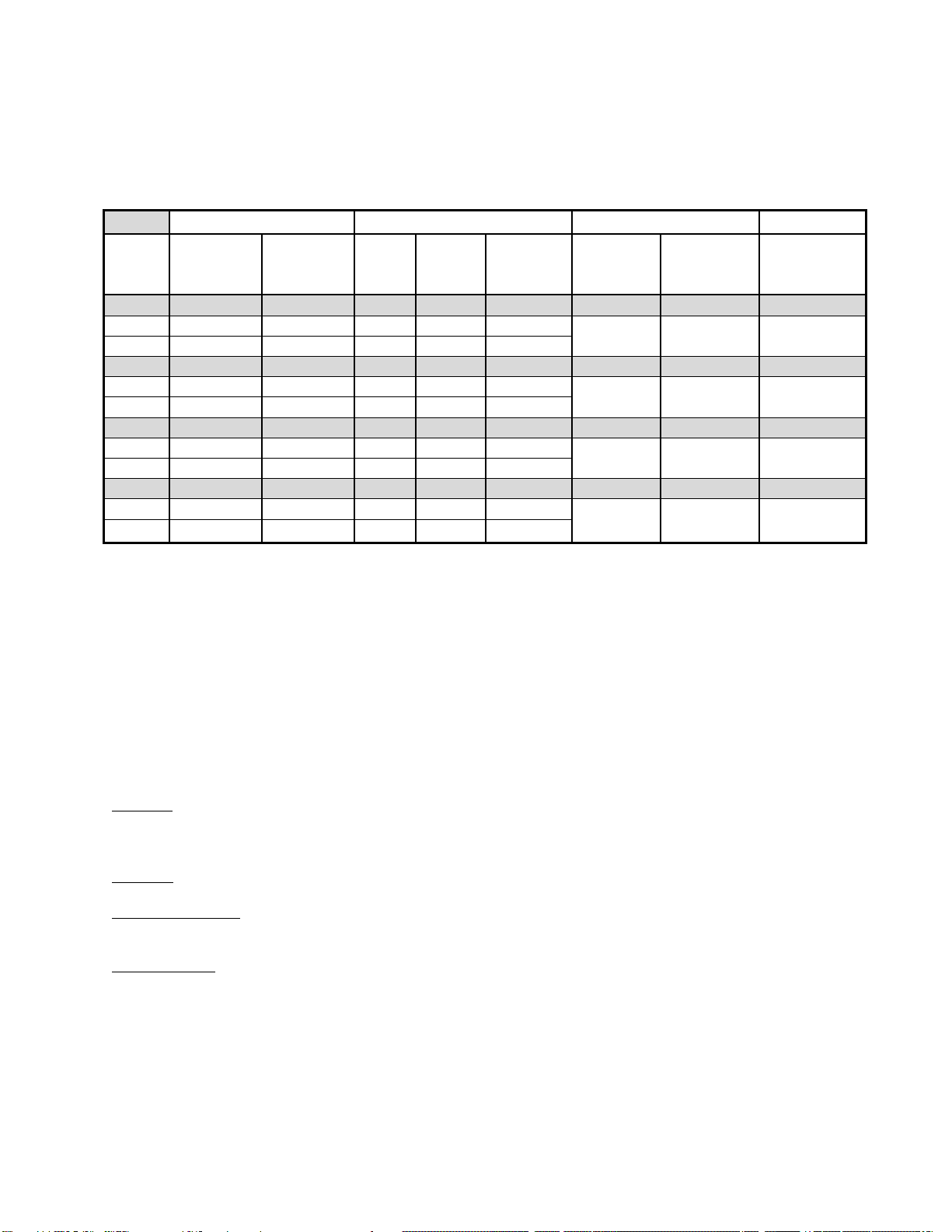
10 DS210 Compatible Probes and Mounting Brackets
The DS210 is compatible with 4 sizes of probe covering overlapping ranges from 0.51mm (0.01”) to
6.35mm (0.25”). Each probe is available with a spring bracket (PNs: BRXXAL). Spring brackets are
recommended, as they ensure that the probe makes good contact with the sample, as is required for
proper operation of the DS210. Refer to Table 10.1 for details.
Probe Range
Probe Dimensions
Thread
Accessories
Probe
Model
#
Min
Thickness*
Max
Thickness* Dia. Height
(Body)
Height
(Overall)
Probe
Body Connector Spring
Bracket
PE36M
0.25mm
3.05mm
36mm
61mm
72mm
M36 x
1.5mm
M12 x 1mm BR36AL
0.01"
0.12"
1.42"
2.40"
2.83"
PE42M
0.25mm
4.31mm
42mm
83mm
94mm
M42 x
1.5mm
M12 x 1mm BR42AL
0.01"
0.17"
1.65"
2.11"
3.70"
PE54M
0.25mm
5.82mm
54mm
96mm
107mm
M54 x
0.75mm
M12 x 1mm BR54AL
0.01"
0.23"
2.13"
3.78"
4.21"
PE75M
0.25mm
6.35mm
75mm
125mm
136mm
M75 x
1.5mm M12 x 1mm BR75AL
0.01"
0.25"
2.95"
4.92"
5.35"
Table 10.1: PEXXM Probe Specifications
*Probe range is referred to in terms of single metal thickness.
10.1 Notes on Probe Ranges
With improvements in the firmware of the DS210, PEXXM probe response is now profiled across a range
of steel samples and stored within the memory of the probe. This allows for more accurate measurement,
offers an estimate of metal thickness on the RS232 serial data port, and may, in some cases, offer an
extended range of the probes metal measuring capability. This range, however, varies for each individual
probe and the specific metal material being detected. The ranges given in Table 10.1 are based on
testing of manufactured probes with our set of steel samples. Performance above or below these ranges
will vary probe to probe and (more so) metal material to metal material.
Air Gaps: Any air gap between the face of the probe and metal sheets, will cause a significant change in
the range of metal thickness the DS210 detect. If the system is to be operated with an air-gap, the air-gap
distance must be constant when calibrating and gauging.
Coatings: Any coating on metal can also affect the reading of metal thickness and effective range.
Metal Composition: We at Prime Controls have characterized all probes to a set of metal samples. Metal
of different composition will have different results including effective range.
Legacy Probes: Older probes which were not profiled are still compatible with newer versions of firmware
(as are the previous generation PE probes without memory). However, they will not be as accurate. It is
highly recommended to use a TWO POINT CALIBRATON when using legacy probes.

11
11 Miscellaneous Functions
11.1 Firmware Version
The version of firmware within a DS210 may be checked by holding down the Calibrate Button while
power is applied. The SINGLE led will flash the major version, the UNDER led will then flash the
minor version. This process will repeat twice, and then normal operation will commence.
For example:
•Version is 2.1
•SINGLE flashes ON for ½ second, OFF for ½ second
•SINGLE flashes ON for ½ second, OFF for ½ second (2 flashes total)
•UNDER flashes On for ½ second, OFF for ½ second (1 flash total)
•No LEDs flash for 1 second
•SINGLE flashes ON for ½ second, OFF for ½ second
•SINGLE flashes ON for ½ second, OFF for ½ second
•UNDER flashes On for ½ second, OFF for ½ second (1 flash total)
•Normal operation commences with probe initialization.
The firmware version is also contained within the initialization message sent from the RS-232 port at
power-on.
11.2 Controller Under Voltage
In the event of insufficient input voltage to the DS210 during measurement, an Under Voltage Failure
indication will be displayed. This condition is indicated by the STATUS LED turning a fast blink of the
Single LED and steady on of the Under LED. If this failure occurs, operation of the DS210 will cease,
and the outputs will be set to the Error Condition state (No-Double OFF, Under On).
The DS210 will reset if power is cycled. However, this failure is an indication that the input voltage is
too low or the power cables to the unit are too long or too high a gauge. See section 13.1.1 Power
Requirements for more details.
11.3 Controller Malfunction
In the event of malfunction of the DS210’s microcontroller, a Controller Failure indication will be
displayed. This condition is indicated by the STATUS LED turning RED, and all of the other LEDs
turning ON steady. If this failure has occurred, operation of the DS210 will cease, and the outputs will
be set to the Error Condition state (No-Double OFF, Under On).
The DS210 should recover if power is cycled. If it does not, or if this happens repeatedly, contact the
Prime Controls Inc for support.
12 DS210 Communications Interface Commands
DS210 commands are optimized for use with a simple terminal program, such as Hyperterminal. They are
issued by simply typing a command character and (depending on the command) a parameter, followed by
the Enter key.
DATA is sent at 9600 baud, No parity, 8 data bits, 1 stop bit (9600 N81). The most pleasing display will
generally be achieved if the terminal program is set for new-line upon received and sent Carriage-Return,
and local echo of typed characters.
Text Mode Commands are divided into Run Time Commands, and Diagnostic Commands.
12.1 Run Time Commands
Run time commands are issued while the DS210 is in full operation. They include Memory Select,
Text Mode Select, Reset, and Diagnostics Mode.

12
12.1.1 Reset Command
Syntax: <R><Enter>
<r><Enter>
The reset command causes the DS 210 to perform a soft reset. This is the same as cycling
power. The DS210 will cease normal operation, and look for the probe to be clear of metal, and
then perform the initialization procedure. Normal operation then resumes.
12.1.2 Diagnostics Command
Syntax: <D><Enter>
<d><Enter>
The Diagnostics command will cause the DS210 to cease operation, and enter the Diagnostics
Mode. At this time, serial port will display the Diagnostics Menu. Refer to the Diagnostics section
for details.
12.1.3 Memory Select Command
Syntax: <M> <#><Enter>
<m><#><Enter>
Note: # is a single digit number from 0-7.
The Memory Select command allows the user to select one of the eight available calibration
memories within each probe. This selection is persistent when probes are changed, or when
power is cycled, or the DS210 is Reset. For example, if channel 1 is selected, every probe
subsequently connected to the DS210 will use its memory 1 calibration values.
Upon receipt of a complete, valid memory select command, the DS210 ceases operation,
changes to the selected memory, and performs a Reset (the same as the Reset command).
The memory select command is only available for PEXXM (where XX is the probe size: 36, 42,
54, or 75). An error will result if the command is issued while a PEXX probe is connected, as
these probes do not have the necessary internal memory. The M value has no effect on the
PEXXM probe’s stored calibration.
12.1.4 Text Mode Select Command
Syntax: <T> <#><Enter>
<t><#><Enter>
The Text Mode Select command allows the user to select one of the three available text modes
DS210 status messages. This selection is persistent when probes are changed, when power is
cycled, or the DS210 is Reset. A heading will be displayed each time a Text Mode selection is
made (even if the mode is the same as that already selected). Details of the three text modes are
as follows:
T0: No reading data is sent to the serial port.
T1: The most recent reading and calibration memory selection
Pb:NNN Mtl:NNN(.NNN") CalMem:N
Where
•N is a number from 0-9
•Pb is the most recent raw sensor reading of the probe in counts

13
•Mtl is the most recent data reading in counts, adjusted in accordance to the
properties of that specific probe
•The second value for Mtl is the most recent reading in approximate metal
thickness.
•CalMem is the currently selected calibration memory spot within the probe
(0-7)
T2: Last reading, Cal Value, Double & Under thresholds, Cal Memory, and Probe Max
Pb:NNN Mtl:NNN(.NNN”) Cv:NNN(.NNN") Dbl:NNN(.NNN”) Und: NNN(.NNN”) CalMem:N Max:NNN
Where
N is a number from 0-9
Pb is the current raw sensor data from the probe in counts
Mtl is the current metal thickness reading in counts and approximate metal thickness
Cv is the calibrated single thickness in counts then in approx metal thickness
Dbl is the threshold for a Double in counts then in approx metal thickness
Und is the threshold for an Under in counts and in approx metal thickness
CalMem is the currently
Max is the maximum thickness in counts the attached probe is capable of measuring in
raw probe sensor data.
Note: if a “?” follows Probe Max: this indicates you are using a legacy probe with no
memory or that your probe does not have a calibration curve stored in the probe. In these
cases, the controller is using a default calibration curve. It will function fine for double
sheet detection but will not accurately display metal thickness. Calibration curves where
implemented in March of 2016 to improve accuracy of probe readings and allow for
approximate metal thickness gauging.
12.2 Diagnostics
When the DS210 diagnostics mode is selected, the DS210 ceases operation, switches to the
diagnostics mode, and sends the diagnostics header and menu of commands to the communications
interface:
DS210 Diagnostics
Firmware 5.7
X - Exit Diagnostics
I - Display Inputs
L - Control LEDs With Switches
O - Control Outputs With Switches
M – Memory Select
H - Display Sensor
C - Display Probe Data
R - Display Probe Range
>
Available commands, while in the diagnostics mode are detailed in the following subsections.
12.2.1 X – Exit Diagnostics
Syntax: <X><Enter>
<x><Enter>
Exits from the DS210 Diagnostics mode, Resets, and returns to RUN mode.
12.2.2 I - Display Inputs
Syntax: <I><Enter>

14
<i><Enter>
The current state of the internal calibrate button, external calibrate input, external RESET input,
probe-mounted proximity switch, and the 6 DIP Switches are displayed continuously.
I - Display Inputs
Hit any key to abort DIP SW
CALBtn ExtCAL ExtRST PROX 123456
0 0 0 1 101111
Be sure to return the switches to their correct settings before exiting the diagnostics mode.
Any key exits the mode, and displays the Diagnostics menu.
12.2.3 L - Control LEDs With Switches
Syntax: <L><Enter>
<l><Enter>
SW1-1 – SW1-6 control the state of the front panel LEDs.
1 – UNDER
2 – SINGLE
3 – DOUBLE
4 – METAL
5 -STATUS (RED)
6 – STATUS (GRN)
Be sure to return the switches to their correct settings before exiting the diagnostics mode.
Any new key exits the mode, and displays the Diagnostics menu.
12.2.4 O - Control Outputs with Switches
Syntax: <O><Enter>
<o><Enter>
Option switches 1-6 control the state of the DS210 Outputs.
O - Control Outputs With Switches
1=PNP/NPN 2=METAL 3=UNDER 4=DOUBLE 5=TP12 6=NU
1-PNP/NPN: This selects whether the outputs will behave as PNP or NPN (See sections 4 & 6).
2-4: These switches control the states of their respective outputs.
Switch 5 controls an on board test point
Switch 6 is not used
Be sure to return the switches to their correct settings before exiting the diagnostics mode.
Any key exits the mode, and displays the Diagnostics menu.
12.2.5 Memory Select Command
Syntax: <M> <#><Enter>
<m><#><Enter>

15
Note: # is a single digit number from 0-7.
The Memory Select command allows the user to select one of the eight available calibration
memories within each probe. This selection is persistent when probes are changed, or when
power is cycled, or the DS210 is Reset. For example, if channel 1 is selected, every probe
subsequently connected to the DS210 will use its memory 1 calibration values.
Upon receipt of a complete, valid memory select command, the DS210 ceases operation,
changes to the selected memory, and performs a Reset (the same as the Reset command).
The memory select command is only available for PEXXM (where XX is the probe size: 36, 42,
54, or 75). An error will result if the command is issued while a PEXX probe is connected, as
these probes do not have the necessary internal memory. The M value has no effect on the
PEXXM probe’s stored calibration.
12.2.6 H – Display Sensor
Syntax: <H><Enter>
<h><Enter>
The output of the sensor in the currently connected probe is displayed continuously. As an aid for
tracing noise problems, the highest and lowest readings since the command was invoked are
also displayed.
A few counts of variation from high to low is normal.
Read Hall Sensor
hall= 491 high= 494 low= 491
Any key exits the mode, and displays the Diagnostics menu.
12.2.7 C - Display Probe Calibration Data
Syntax: <C><Enter>
<c><Enter>
The content of the currently selected probe memory is displayed, in engineering units.
L - Display Probe CAL Block from Probe Memory
11 = 42mm, 12 = 36mm, 13 = 54mm, 14 = 75mm
Probe Memory = 0
Probe ID = 12
calvalue = 0519
doublethreshold = 0601
underthreshold = 0437
zerothickness = 0832
update_count = 0000
update_count_2 = 00
current = 00
Any key exits the mode, and displays the Diagnostics menu.
12.2.8 Display Probe Range
Syntax: <R><Enter>
<r><Enter>
The range of the currently attached probe is displayed in counts and in approximate metal
thickness. The maximum displayed is not the maximum thickness of a single metal thickness. It is

16
the maximum thickness the probe can measure before no longer having resolution. Any metal
thickness beyond this probe max will indicate a double. Example below:
Range Low:002(.010") High:652(.210")

17
13 Specifications
13.1 Electrical Specifications
13.1.1 Power Requirements
Input Voltage: 22.5-28VDC, 24VDC Supply Recommended*
Input Current: 1.85A peak, 0.6A RMS, 2ADC Supply Required
Input Power: 44.4W peak, 14.4W RMS
Note that the DS210 uses efficient switch-mode regulators for its operation, and so dissipates
very little heat internally. The majority of heat dissipation is in the probes.
*The supply voltage may require adjustment to compensate for voltage loss along the power
supply cable. A 15m 24 gauge (0.25mm^2) cable requires 26.5VDC at the power supply to
properly power the DS210.
13.1.1 Input Specifications
Switch 3 ON – PNP: Inputs active when pulled to 24V, inactive otherwise
Switch 3 OFF: - NPN: Inputs active when pulled to ground, inactive otherwise.
13.1.2 Output Specifications
All outputs on the DS210 are rated at 50mA DC, and are internally protected by a resettable fuse.
Output behavior is switchable between PNP and NPN, according to the position of switch 3.
+VDC in PNP Mode (Sourcing) is 22-24VDC. See below and Section 8:
Switch 3 ON - PNP: METAL & UNDER are normally open, NO DOUBLE is normally closed
Switch 3 OFF - NPN:METAL & UNDER are normally open, NO DOUBLE is normally closed
13.2 Temperature / Environmental
The DS210 and its probes are rated for operation between 0°C and 50°C (32°F to 122°F). Humidity
can range from 10% to 90% non-condensing.
13.3 Dimensions
Overall dimensions are 115mm H x 96mm W x 41mm D (4.53” H x 3.78” W x 1.61” D)
13.4 Weight
DS210 weight is 233g (8.2Oz), not including cables and probes.
14 Document Revision history
Revision Date Comment
A 6/6/2016 Initial Release of OPI V5.6 to reflect firmware change.
B 8/30/16 Corrected Wiring Chart for RS232 Connection (Sec 4.3).
C 09/28/16 Added EthernetIP notes (Sec 1) and document clarifications.
D 06/20/17 Changed minimum input voltage to 22.5V from 22.0V. Added notes on
use of 15m power supply cable.
E 07/07/17 Firmware version 5.7. Undervoltage fault added.
F 11/17/21 Expanded probe sensing ranges in table 10.1

18
15 LIMITATION AND EXCLUSION OF WARRANTIES
All goods purchased from PRIME CONTROLS, INC. shall be free from defects in materials, design and
workmanship under normal conditions of use for one year from the date of shipment. THIS WARRANTY
IS THE SOLE WARRANTY AND IS EXPRESSLY IN LIEU OF ALL OTHER WARRANTIES, EXPRESS
OR IMPLIED, INCLUDING BUT NOT LIMITED TO ANY IMPLIED, WARRANTY OF MERCHANTABILITY
OF FITNESS FOR A PARTICULAR PURPOSE. THE LIABILITY OF PRIME CONTROLS TO ANY
PURCHASER SHALL BE LIMITED EXCLUSIVELY TO THE COST OF REPLACEMENT OR REPAIR OF
DEFECTIVE PARTS, AND SHALL NOT INCLUDE LIABILITY FOR ANY DIRECT, CONSEQUENTIAL
OR INCIDENTAL DAMAGES WHATSOEVER, WHETHER FORESEEN OR UNFORESEEN,
INCLUDING BUT NOT LIMITED TO LOST PROFITS, LOST SALES, OR INJURY TO PERSONS OR
PROPERTY.
Table of contents
Popular Industrial Equipment manuals by other brands

Heidolph
Heidolph LABOROTA 20 control automatic Series instruction manual

Husqvarna
Husqvarna 2-20DT Operator's manual

altitude
altitude COMMSCOPE FIST-GCO2 Installation instruction

Parker
Parker PHK user manual

Donaldson Torit
Donaldson Torit Dalamatic DLMV Series Installation and operation manual

ABB
ABB Power2 340-H44 Operation manual


