5
Donaldson Company, Inc.
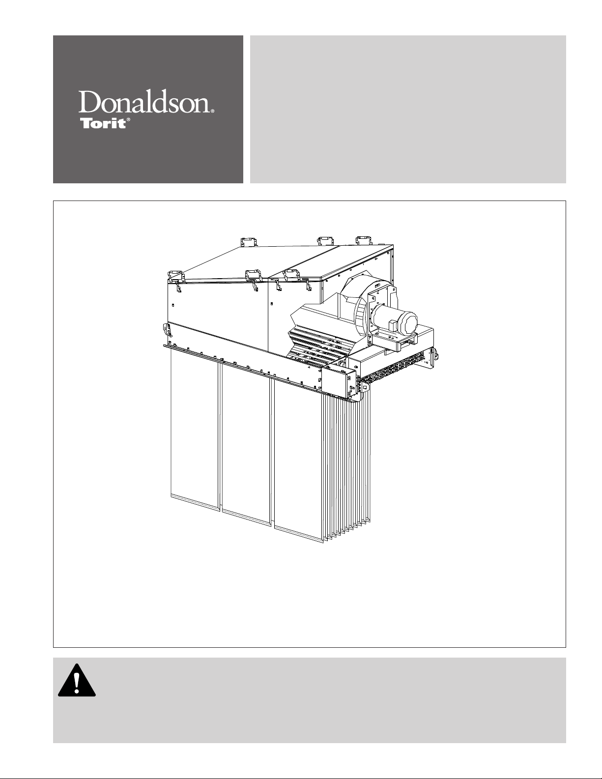
The unit is suitable for either indoors or outdoors.
Reference the Rating and Specification Information.
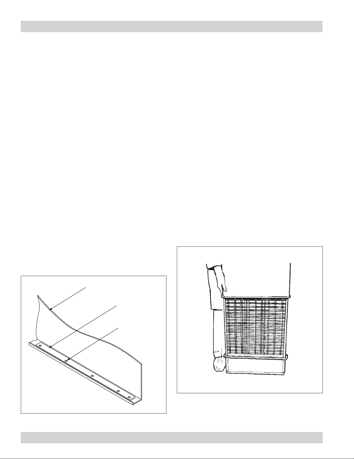
Foundations or Support Framing
Prepare the foundation or support framing in the
selected location. Foundation or support framing must
comply with local code requirements and may require
engineering.
Foundation and support framing must be capable of
supporting dead, live, wind, seismic and other applicable
loads. Consult a qualified engineer for final selection of
foundation or support framing.
Unit Location
Donaldson Torit equipment is not
designed to support site installed
ducts, interconnecting piping, or electrical
services. All ducts, piping, or electrical
services supplied by others must be adequately
supported to prevent severe personal injury
and/or property damage.
When hazardous conditions or materials are
present, consult with local authorities for the
proper location of the collector.
If combustible materials will
be processed through this
collector, local codes may require the collector
be located either outside or adjacent to an
exterior wall to accommodate devices related
to a fire or explosion mitigation strategy.
Consult local codes prior to installation.
Locate the collector to ensure easy access to electrical
and compressed air connections, to simplify solids
collection container handling and routine maintenance,
and to ensure the straightest inlet and outlet ducts.
Site Selection
This unit can be located on a foundation or structural
framing.
Provide clearance from heat sources and avoid any
interference with utilities when selecting the location.
Portable units require special installation
accommodations.
Note: Units with explosion vents are not available
in portable configurations.
If unit is to be located outdoors, an appropriate exhaust
and remote electrical controls may be necessary.
When outdoor locations are
selected, always mount motors
with drain holes pointed down for proper
drainage of moisture.
Rigging Instructions
Suggested Tools & Equipment
Clevis Pins and Clamps Lifting Slings
Crane or Forklift Pipe Sealant
Drift Pins Pipe Wrenches
Drill and Drill Bits Screwdrivers
End Wrenches Socket Wrenches
Adjustable Wrench Spreader Bars
Torque Wrench (inch/lbs, 9/16-in Socket)
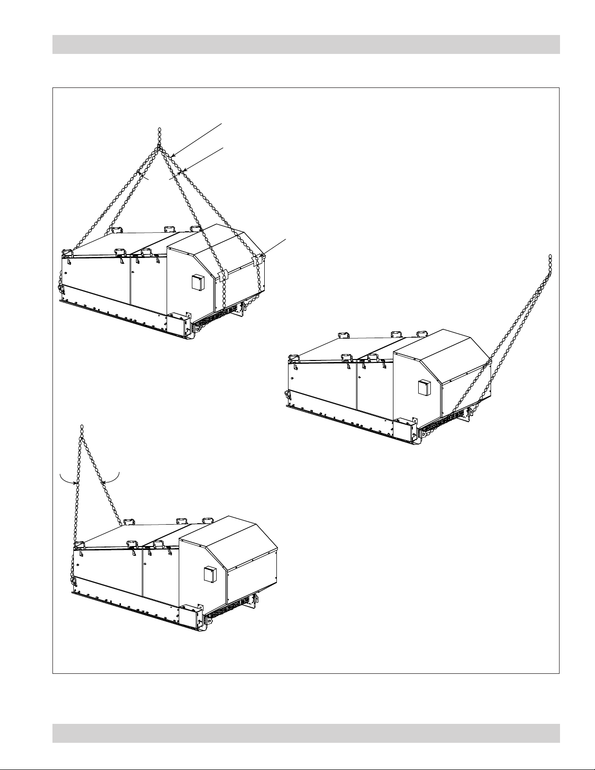
Hoisting Information
Failure to lift the collector
correctly can result in severe
personal injury or property damage.
Use appropriate lifting equipment and adopt
all safety precautions needed for moving and
handling the equipment.
A crane or forklift is recommended for
unloading, assembly, and installation of the
collector.
Location must be clear of all obstructions, such
as utility lines or roof overhang.
Use all lifting points provided.
Use clevis connectors, not hooks, on lifting slings.
Use spreader bars to prevent damage to unit’s casing.
Check the Specification Control drawing for weight
and dimensions of the unit and components to ensure
adequate crane capacity.
Allow only qualified crane operators to lift the equipment.
Refer to applicable OSHA regulations and local codes
when using cranes, forklifts, and other lifting equipment.
Lift unit and accessories separately and assemble after
unit is in place.
Use drift pins to align holes in section flanges during
assembly.