Prime Karts FATAL VISION ROADSTER Instructions for use

BY
[ SINGLE SEATER ]
Step By Step
Assembly Instructions
and Maintenance Guide

[ 2 ] Fatal Vision® Roadster Assembly Instructions and Maintenance Guide | © Innocorp, ltd. www.fatalvision.com
FATAL VISION® ROADSTER STEP BY STEP ASSEMBLY INSTRUCTIONS [ SINGLE SEATER ]
Scan QR code below or visit
https://vimeo.com/709244660 to
review the assembly guide video.
TO REFER TO THE ASSEMBLY VIDEO USE THE TIMESTAMPS THROUGHOUT THIS GUIDE
[ 3 ] Fatal Vision® Roadster Assembly Instructions and Maintenance Guide | © Innocorp, ltd. www.fatalvision.com
FATAL VISION® ROADSTER STEP BY STEP ASSEMBLY INSTRUCTIONS [ SINGLE SEATER ]
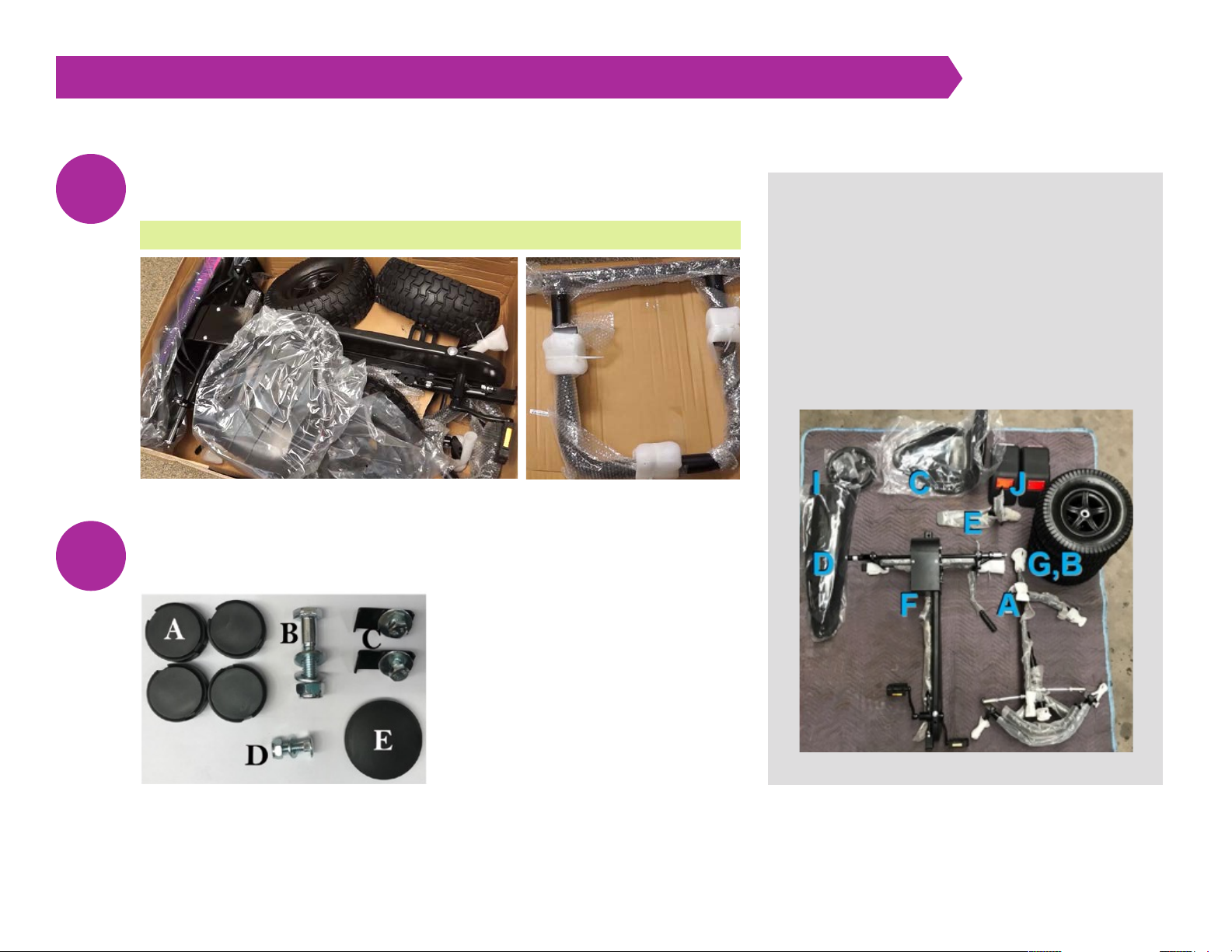
Unpack your Roadster. Remove the top box and lay out all pedal kart
components to verify that nothing is missing from the package.
Unpack the hardware set located inside the plastic steering wheel bag.
1
2
A: 1 front assembly
B: 1 drive wheel
C: 1 seat
D: 1 front spoiler
E: 1 hardware bag
J: 1 fender set
F: 1 rear assembly
G: 3 coast wheels
H: 1 bumper frame
(not shown below)
I: 1 sterring wheel
BOX CONTAINS THE FOLLOWING:
HARDWARE ASSEMBLY SET
INCLUDES:
A: 4 wheel hub caps
B: 1 frame connection bolt assembly
C: 2 spoiler mounting brackets
D: 1 seat/seat frame hardware
E: 1 steering wheel cap
VIDEO 0:10 UNPACK THE ROADSTER

[ 4 ] Fatal Vision® Roadster Assembly Instructions and Maintenance Guide | © Innocorp, ltd. www.fatalvision.com
FATAL VISION® ROADSTER STEP BY STEP ASSEMBLY INSTRUCTIONS [ SINGLE SEATER ]
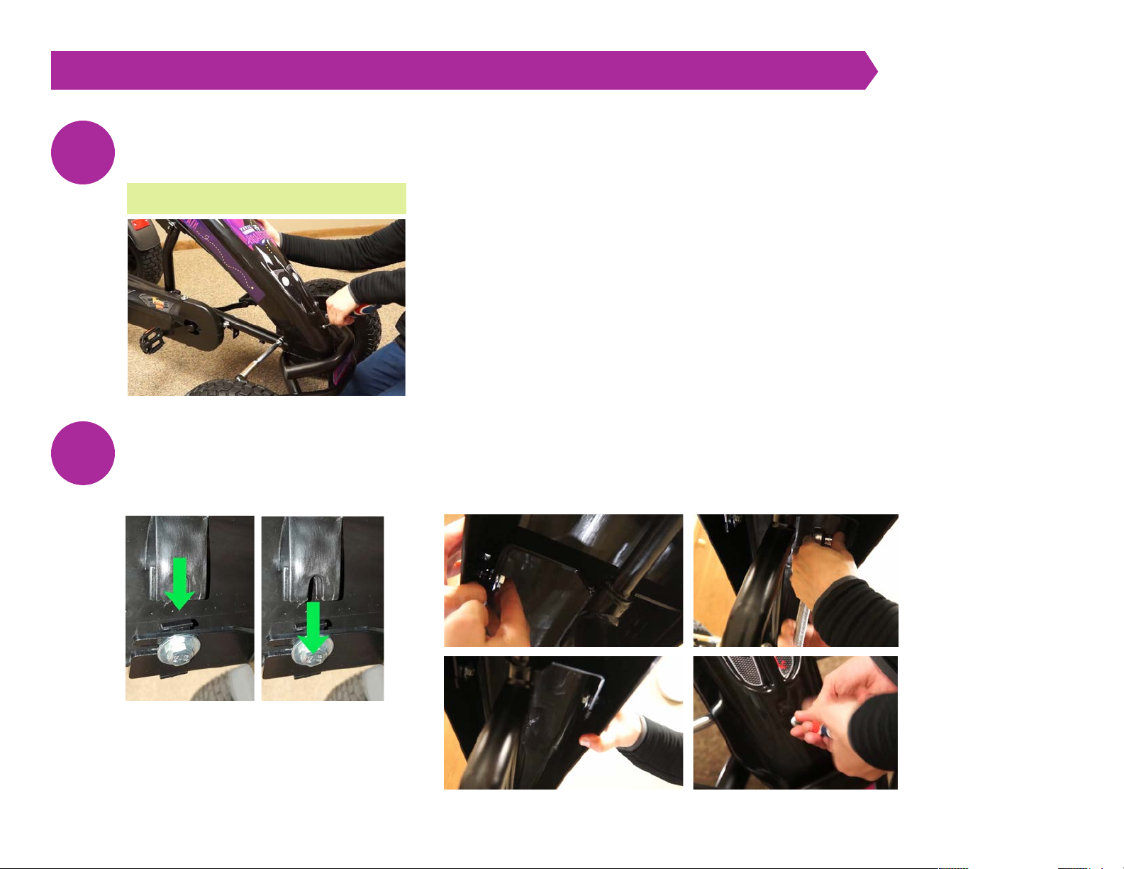
Install the rear fenders: Locate the two fenders and identify the left and right fenders by looking on the inside of
the fenders and finding L for left and R for right.
Install the fenders by sliding them over the fender support bracket as shown and lightly tap them on. You may need
to move the hand brake lever to install the fenders fully.
3
VIDEO 0:32 INSTALL THE FENDER SET

[ 5 ] Fatal Vision® Roadster Assembly Instructions and Maintenance Guide | © Innocorp, ltd. www.fatalvision.com
FATAL VISION® ROADSTER STEP BY STEP ASSEMBLY INSTRUCTIONS [ SINGLE SEATER ]
IMPORTANT: BEFORE ASSEMBLY, FILL THE TIRES TO 25 PSI.
Attach the Drive Wheel: The drive wheel does not have a bearing on each side like the coast wheels. Instead, there is a bushing on
one side and a star pattern on the other side. Using a 17mm socket, remove the bolt and washer from the drive side of the rear axle.
Slide the drive wheel over the square on the drive axle until the inside of the wheel makes contact with the stop washer. A rubber
mallet may be used. Reinstall the bolt and washer and tighten using a 17 mm socket.
Attach the coast wheel: Using a 17mm socket, remove the bolt and washer from the coast side of the rear axle and the first black
spacer. Slide the coast wheel on the axle with the air fill valve facing INWARD. Reinstall the bolt and washer and tighten using the
17mm socket. IMPORTANT: Remove the first black metal spacer tube with the silver sticker. DO NOT remove the second black
plastic spacer. The pedal chain drive will not work correctly without the second spacer.
5
4
6
VIDEO 1:13 ATTACH THE REAR WHEELS
[ 6 ] Fatal Vision® Roadster Assembly Instructions and Maintenance Guide | © Innocorp, ltd. www.fatalvision.com
FATAL VISION® ROADSTER STEP BY STEP ASSEMBLY INSTRUCTIONS [ SINGLE SEATER ]
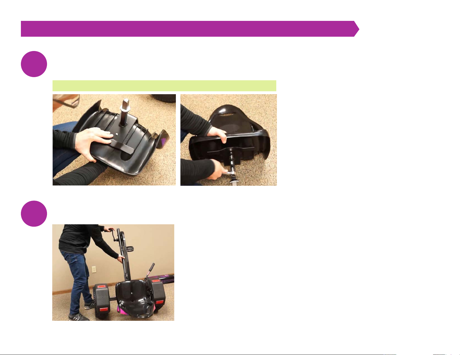
Assemble the seat: Slide the metal seat frame into the slot on the back of the plastic seat and line up the
hole on the seat frame with the hole on the seat. Insert the seat bolt (D in hardware) through the plastic seat,
then attach the washer and nut on the back of the metal seat frame using a 13mm wrench or socket.
Place the seat in the last seat position and stand the kart up on its end, resting on the seat back.
7
8
VIDEO 3:18 ASSEMBLE THE SEAT

[ 7 ] Fatal Vision® Roadster Assembly Instructions and Maintenance Guide | © Innocorp, ltd. www.fatalvision.com
FATAL VISION® ROADSTER STEP BY STEP ASSEMBLY INSTRUCTIONS [ SINGLE SEATER ]
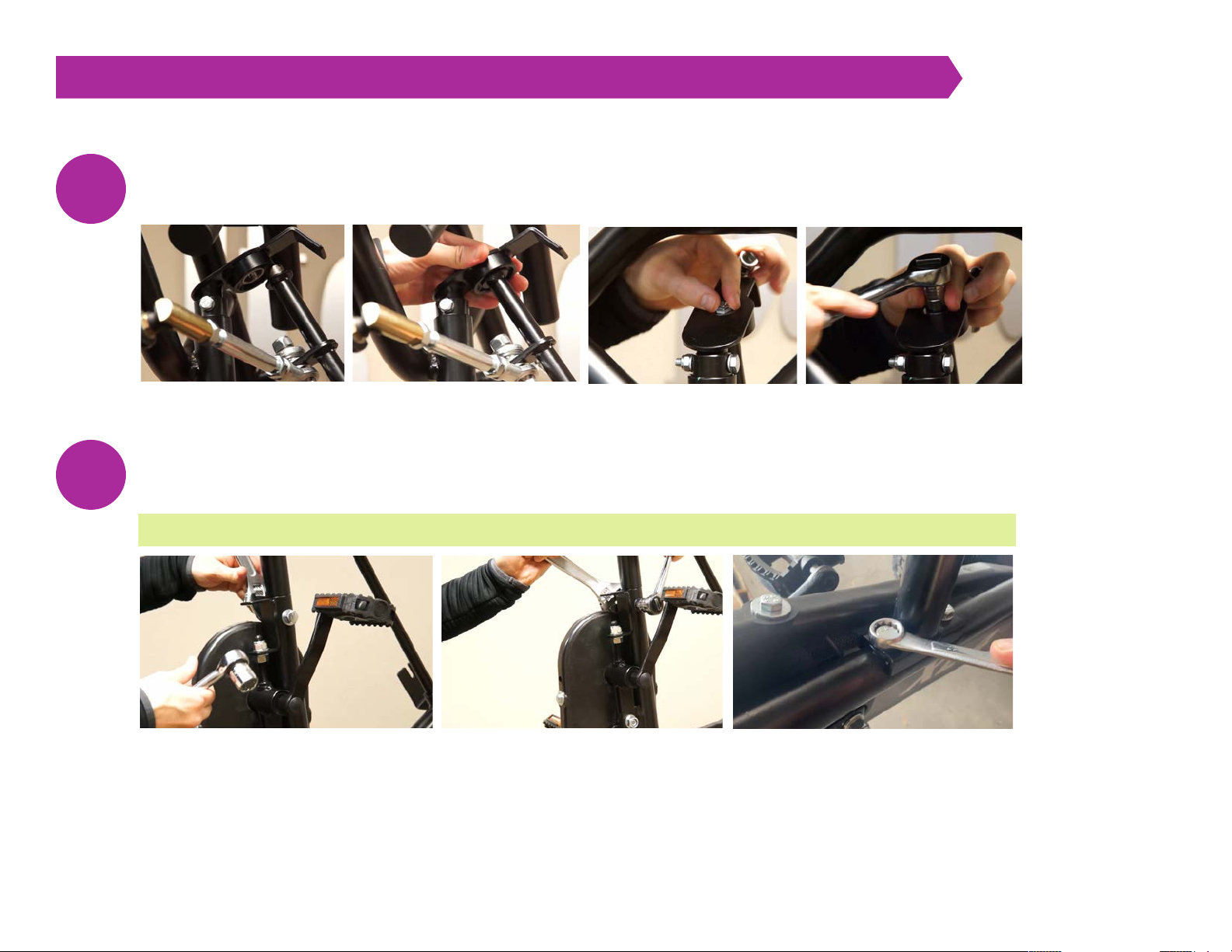
Remove all pre-assembled hardware: 2 bolt assemblies from the front axles (17mm socket), 1 bolt from the end
of the steering shaft (13mm wrench), 1 screw from the front of the spoiler mount bracket (Philips screwdriver),
and 1 bolt from the steering wheel mounting plate (13mm socket). Be careful to set and remember where each
bolt belongs.
Use a 17mm socket or wrench and remove the 2 existing bolts/washers by the chain drive on the rear assembly.
9
10
VIDEO 4:17 REMOVE ALL PRE-ASSEMBLED HARDWARE

[ 8 ] Fatal Vision® Roadster Assembly Instructions and Maintenance Guide | © Innocorp, ltd. www.fatalvision.com
FATAL VISION® ROADSTER STEP BY STEP ASSEMBLY INSTRUCTIONS [ SINGLE SEATER ]
Slide the front assembly into the tube of the rear assembly.
Use a 17mm socket or wrench to replace the 2 bolts/washers by the chain drive on the rear assembly to
attach the steering column brace. Do not tighten the front bolt all the way yet. This maneuverability is
needed to shift and position the steering rod next.
11
12
VIDEO 5:45 ATTACH FRONT ASSEMBLY ONTO REAR ASSEMBLY
[ 9 ] Fatal Vision® Roadster Assembly Instructions and Maintenance Guide | © Innocorp, ltd. www.fatalvision.com
FATAL VISION® ROADSTER STEP BY STEP ASSEMBLY INSTRUCTIONS [ SINGLE SEATER ]
Install the end connection bolt and washer onto the end of the steering rod and tighten using a 13mm socket.
Install the frame connection bolt, washers, and nut assembly. (B in hardware) Tighten using 19mm wrenches/sockets.
Afterward, finish tightening the bolts to secure the steering column brace.
13
14
VIDEO 7:06 INSTALL FRAME CONNECTION BOLT
[ 10 ] Fatal Vision® Roadster Assembly Instructions and Maintenance Guide | © Innocorp, ltd. www.fatalvision.com
FATAL VISION® ROADSTER STEP BY STEP ASSEMBLY INSTRUCTIONS [ SINGLE SEATER ]
Attach both front wheels and tighten using a 17mm socket. The air intake valve stems should face inward while
attaching the wheels.
Place the spoiler mounting brackets (C in hardware) on the frame metal support brackets.
15
16
VIDEO 8:00 ATTACH FRONT WHEELS
VIDEO 9:34 INSTALL FRONT SPOILER
[ 11 ] Fatal Vision® Roadster Assembly Instructions and Maintenance Guide | © Innocorp, ltd. www.fatalvision.com
FATAL VISION® ROADSTER STEP BY STEP ASSEMBLY INSTRUCTIONS [ SINGLE SEATER ]
Place the spoiler on the frame, and replace the Philips head screw through the hole at the bottom of the spoiler into
the metal tab on the kart. Do not tighten all the way yet.
Position the plastic slots on the
spoiler, so they slide over the metal
clips. As shown, this should trap the
bolt in the ‘U-shaped’ plastic slot gap.
The inside plastic slot must fit between the washer and the frame metal
support bracket. Tighten the bolts using a 13mm socket/wrench, so the
spoiler stays securely. Be careful not to crack the plastic by over-tightening.
Finish tightening the Philips head screw in front to secure the spoiler.
17
18
VIDEO 9:34 INSTALL FRONT SPOILER
[ 12 ] Fatal Vision® Roadster Assembly Instructions and Maintenance Guide | © Innocorp, ltd. www.fatalvision.com
FATAL VISION® ROADSTER STEP BY STEP ASSEMBLY INSTRUCTIONS [ SINGLE SEATER ]
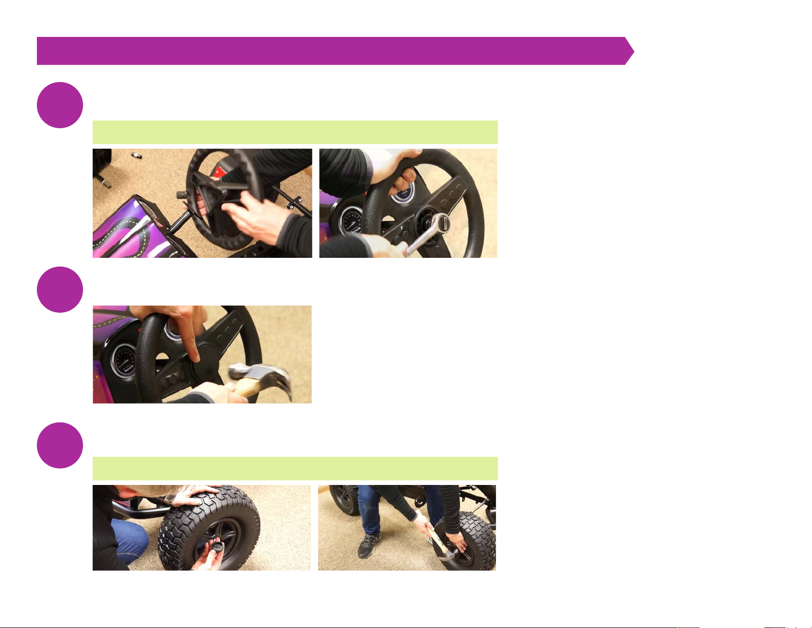
Slide the steering wheel over the triangular plate, and reattach the bolt and washer using the 13mm
socket/wrench.
Gently tap on the steering wheel cap (E in hardware).
Gently tap on the wheel hub caps (A in hardware).
19
20
21
VIDEO 12:29 ATTACH STEERING WHEEL
VIDEO 13:24 ATTACH WHEEL CAPS
[ 13 ] Fatal Vision® Roadster Assembly Instructions and Maintenance Guide | © Innocorp, ltd. www.fatalvision.com
FATAL VISION® ROADSTER STEP BY STEP ASSEMBLY INSTRUCTIONS [ SINGLE SEATER ]
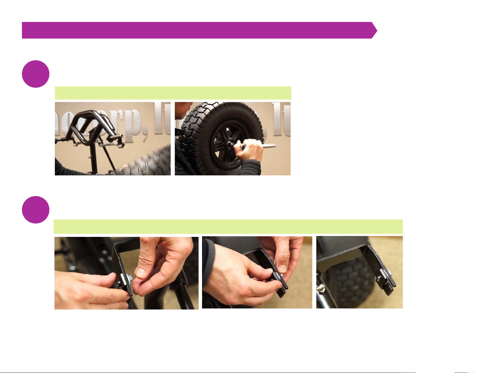
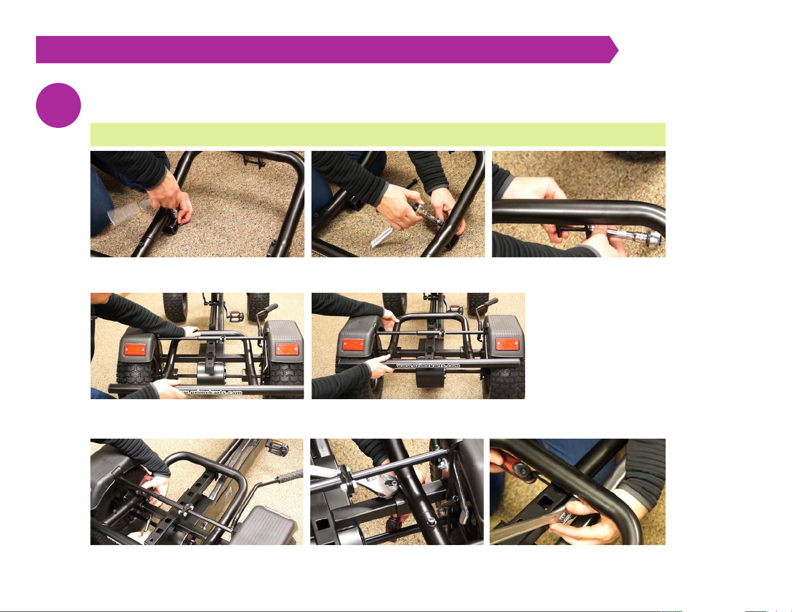
Remove the seat from the kart, and prepare to install the rear bumper frame. Remove the existing
hardware using a 13mm socket/wrench and an Allen/hex wrench.
Slide the rear bumper frame metal tabs onto the square frame of the kart.
Replace the hardware with an Allen/hex wrench and a 13mm socket/wrench.
22
VIDEO 14:14 INSTALL REAR BUMPER FRAME

[ 14 ] Fatal Vision® Roadster Assembly Instructions and Maintenance Guide | © Innocorp, ltd. www.fatalvision.com
FATAL VISION® ROADSTER STEP BY STEP ASSEMBLY INSTRUCTIONS [ SINGLE SEATER ]
Replace the seat, and the Roadster is ready for use.
23

[ 15 ] Fatal Vision® Roadster Assembly Instructions and Maintenance Guide | © Innocorp, ltd. www.fatalvision.com
FATAL VISION® ROADSTER MAINTENANCE [ SINGLE SEATER ]
Fatal Vision® Roadster by Prime Pedal Karts are designed and built to stand up to the most demanding use. But just like a car or
truck, routine maintenance is required to keep your pedal kart performing for many years of use.
*The front and rear chains will stretch when they are first used. Check front and rear chain after the first 8-hour break-in period.
Please Note: Periodic maintenance must be performed on your pedal kart to keep it in safe and good working order. The items
listed here are some common components that will need periodic adjustment or replacement. This maintenance guide is not
meant to be a complete overhaul manual. If you have any questions, please contact Prime Pedal Kart. Current replacement
parts for your model can be found at their website primekarts.com or call toll-free (866) 475-0450.
Item Frequency for Inspection/Maintenance
Wheels and Tires Before Every Event (28psi)
Inspect for Loose Nuts, Bolts and Pedals Before Every Event
Front Chain 20 hours*
Rear Chain 40 hours*
Check Crank Bolts Tightness 40 hours
Check Steering Adjustment 40 hours
Inspect Transmission 80 hours
Grease Front Axles and Steering Shaft 80 hours

[ 16 ] Fatal Vision® Roadster Assembly Instructions and Maintenance Guide | © Innocorp, ltd. www.fatalvision.com
FATAL VISION® ROADSTER MAINTENANCE [ SINGLE SEATER ]
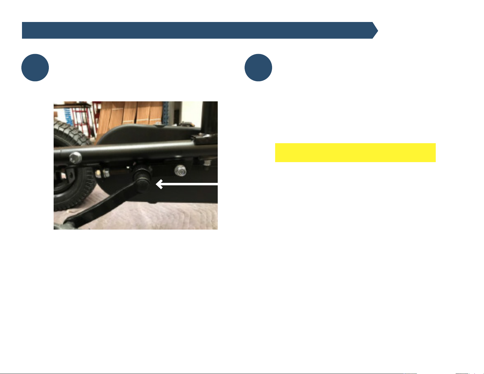
Front Drive Chain Adjustment and Maintenance
The chain on your Pedal Kart is heavy-duty and used on
professional BMX-type bicycles and has a high tensile
strength for rugged use.
However, like all chains, they will stretch with use over
time. They must be checked for proper adjustment. To
check the front chain, remove bolt (A) and lift the top
chain guard. There should be about 1/2” travel by pushing
on the center of the chain. If the chain is too tight, the
transmission and drive components will wear out quickly,
and the kart will be hard to pedal. See the maintenance
table on page 15.
To adjust the front chain, loosen bolt (B) and nut (C)
To tighten the chain, turn nut (D) clockwise to tighten the
chain. Turn counter-clockwise to loosen. After the proper
chain tension is set, re-tighten (B) and (C) parts for your
model. It can be found at our website primekarts.com.
Rear Drive Chain Adjustment and Maintenance
Remove the top and bottom chainguard and loosen the
front chain as described in the previous step. Next, take
off the rear transmission cover by removing the three
bolts.
Next, loosen the nuts on the outside of the transmission
cover and slide the transmission forward to tighten the
rear chain. The chain should have about 1/4” up and
down movement in the center. When the chain is set at
the desired tension, re-tighten the outside nuts on the
transmission. The rear chain should be checked after the
first 8-hour break-in period.
NOTE: After the rear chain has been adjusted, the front
chain will also need an adjustment (refer back to the
previous step to adjust)
1 2
[ 17 ] Fatal Vision® Roadster Assembly Instructions and Maintenance Guide | © Innocorp, ltd. www.fatalvision.com
FATAL VISION® ROADSTER MAINTENANCE [ SINGLE SEATER ]
Crank Bolts Adjustment
Using a 14mm socket, check that the crank bolts are
tight. Be careful not to over tighten. Check the bolts
after every 4 hours of use. to make sure they have not
come loose.
Tire and Wheel Maintenance
The wheels are made out of a robust and flexible
elastomer that allows it to flex if there is impact,
unlike a metal rim that will dent and be damaged
slightly. If you notice any cracks in the edge, it’s time
to replace it. The wheels on Pedal Karts are universal
for the coast wheels and drive wheel. If the wheel
bearings become damaged, replace them as soon as
possible. The proper tire pressure is 28 PSI for
all wheels.
Underinflation of the tires will make the kart
difficult to pedal and possibly damage the wheel.
DO NOT EXCEED 28 PSI. Please note that low tire
pressure can also cause an issue by putting stress
on the inner tubes, especially when applying the
brakes to the rear tires. Tires should be checked
before every event.
If tires become worn or damaged, replace them
immediately.
3 4
[ 18 ] Fatal Vision® Roadster Assembly Instructions and Maintenance Guide | © Innocorp, ltd. www.fatalvision.com
FATAL VISION® ROADSTER MAINTENANCE [ SINGLE SEATER ]
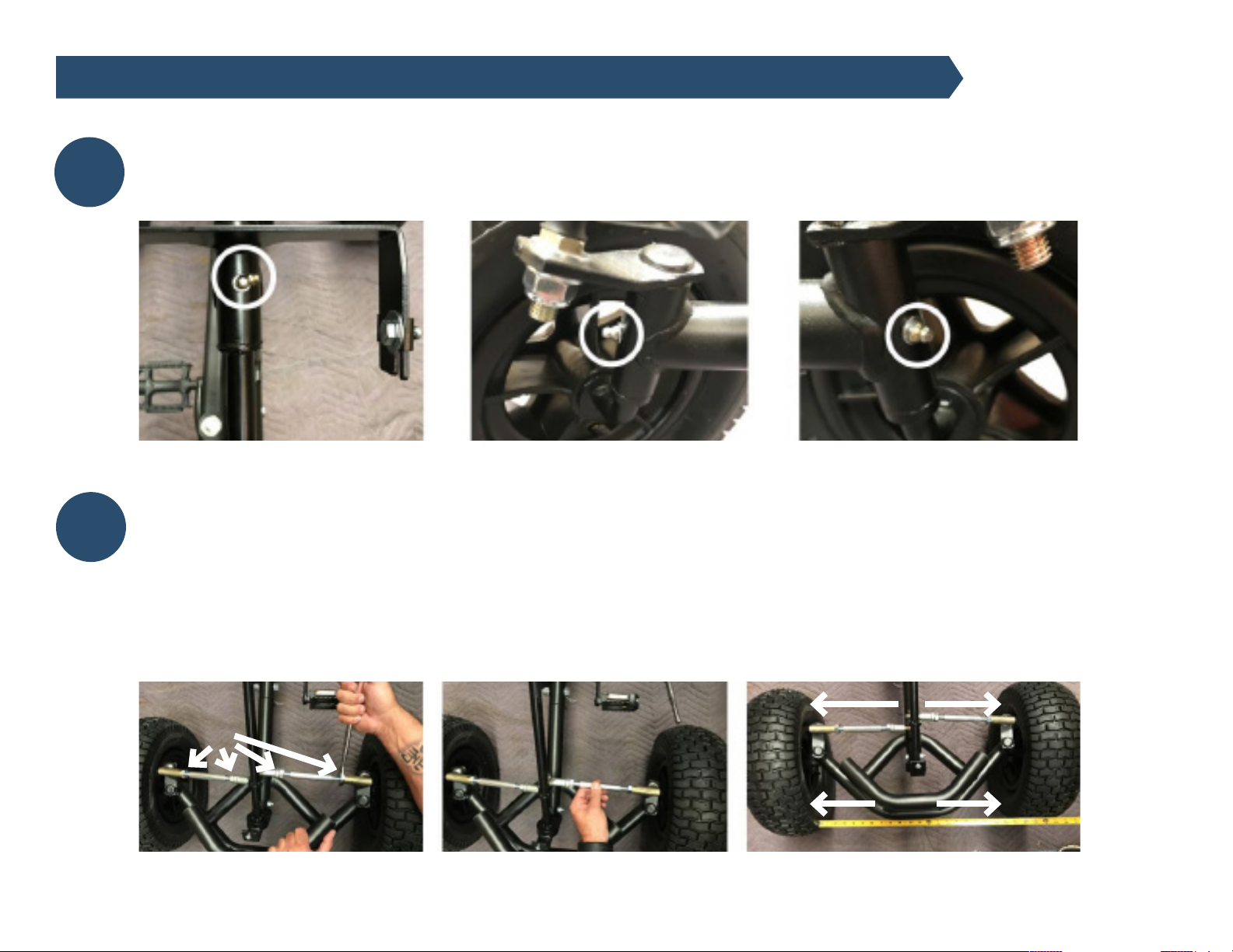
Front Axles and Steering Column Maintenance
Grease the steering wheel column and both front axle zurk fittings every 80 hours of use. Wipe off the excess grease after
you have greased the axle.
Steering Adjustment
If the front wheels are hit hard during impact, it is possible for the front end of the pedal kart to go out of alignment. The
signs of this are excessive or uneven wear on the front tires. To adjust the front wheels, first make sure the steering wheel
is centered, then loosen all 4 jam nuts (A) on the tie rods. Next, turn the center of each tie rod to move the front wheels
closer together, or further apart.
The dimensions from inside front tire to inside front tire (X) should measure the same as the inside back tire to inside back
tire (Y). Make sure to retighten all 4 jam nuts.
5
6
X
Y
A
A

[ 19 ] Fatal Vision® Roadster Assembly Instructions and Maintenance Guide | © Innocorp, ltd. www.fatalvision.com
FATAL VISION® ROADSTER MAINTENANCE [ SINGLE SEATER ]
Steel Frame Maintenance
The frame of the pedal kart is made from strong heavy wall steel tubing and is protected with
durable powder coat paint. If the paint coating becomes damaged exposing the bare steel, touch
up the area with any type of close match spray paint to keep the frame from rusting.
Coaster Brake/Transmission Maintenance
The mounting nuts need to be checked for tightness 80 hours of use. If they loosen up, damage
to the transmission may occur. See Maintenance # 2 for chain adjustment. There are no user
serviceable parts with the coaster brake so if the part becomes worn or damaged, replace it with
a new coaster brake transmission.
8
7

[ 20 ] Fatal Vision® Roadster Assembly Instructions and Maintenance Guide | © Innocorp, ltd. www.fatalvision.com
FATAL VISION® ROADSTER MAINTENANCE [ SINGLE SEATER ]
CHAIN DRIVE TROUBLESHOOTING
Scan QR code below or visit
https://vimeo.com/709636047
to review the chain drive
troubleshooting video.
REPLACING THE TIRE INNER TUBE
Scan QR code below or visit
https://vimeo.com/709637752 to
review the replacing the tire inner
tube video.
OTHER HELPFUL MAINTENANCE VIDEOS


