Primrose Half Cassette User manual

Primrose Awnings
Half Cassette Manual & Electric Instructions
Contents for 2.5m, 3m Awnings
4 x Expansion bolts (2 per bracket)**
2 x Wall brackets
1 x Awning
Contents for 3.5m, 4m Awnings
6 x Expansion bolts (2 per bracket)**
3 x Wall brackets
1 x Awning
Contents for 4.5m Awnings
8 x Expansion bolts (2 per bracket)**
4 x Wall brackets
1 x Awning
Optional Controls
(Depends which set was purchased)
Set A (Remote control kit)
1 x Remote control receiver box
2 x Remote hand-held zappers
1 x 5m electrical wire (3 core) to connect
the remote reciever box to the mains
Set B (Indoor wall switch)
1 x Wall Switch
Set C (Wind, sun, rain sensor)
1 x Remote control receiver box
2 x Remote hand-held zappers
1 x Wind, rain and sun sensor
Primrose Awning Installation Instructions 1
WARNING
We recommend that two people are required
to lift the awning into place.
You may wish to consult a qualified electrician
before installing electrical awnings.
The awning and frame may be supplied with a
plastic wrapper. This should be removed prior
to use.
Plastic bags can be dangerous to children and
babies. Keep out of the reach of babies and
children to avoid the risk of suffocation.
**The expansion bolts supplied are for reinforced
concrete or brick walls. The awnings may be installed
on wooden walls if the wall is sufficiently strong.
Use appropriate screw-threaded or coach bolts.
Hammer drill
14mm masonry drill bit
Chalk or pencil to mark
Laser level or long spirit level
Metric socket spanner set
Adjustable spanner
Tools recommended
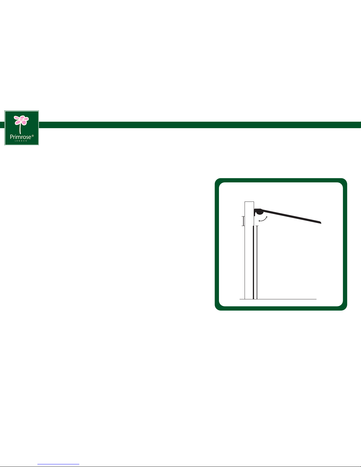
STEP 1: Determine position on the wall and mark up
Height of awning
The recommended height from the ground is 2.5m-3.5m. If you wish to install lower
than this, determine whether there is sufficient headroom when the awning is fully
extended and that any doors can open:
Required headroom
- Allow 20cm above any door frame and check that when opened the door
will not interfere with the awning.
- As a guideline, the awning has a drop of 30 cm (2m projection) to 45cm
(2.5m projection) at a slope of 10 degrees below the horizontal.
The recommended slope is factory pre-set. This can be adjusted with a spanner
any time after fitting: from almost horizontal to approx 30 degrees below the horizontal.
Horizontal positioning of brackets:
Using laser, spirit level or other method, mark an accurate horizontal line at the
required height. Fixing must be directly into brick or concrete. Mortar joints between
the bricks or blocks will not be secure enough to bolt into.
Half cassette and electrical awnings
The bracket positions of Half cassette awnings are factory pre-set: the left-
to-right positions of the brackets in relation to the awning can only be adjusted
a few mm in either direction.
(If this is a problem, our Standard Manual awnings have more flexibility as
to the left-right positioning of the brackets)
Primrose Awning Installation Instructions 2
Side view of awning
Wall
20cm
above
door
frame
Slope can be
adjusted
door

STEP 2: Drill holes
Use a hammer-action electric drill with a 14 mm bit.
Drill 100mm holes into brick or concrete wall in exact position chosen for wall brackets.
Insert an expansion bolt into the drilled hole.
STEP 3: Attach the brackets
Remove the nut and one of the washers from the expansion bolts that are now on
the walls.
Fit bracket into place over wall bolt. Replace the washer and nut and tighten with
a socket spanner. Ensure the bracket is tight against wall before fitting the awning
as the weight of the awning could pull the brackets out of the wall.
STEP 4: Fitting the awning
Because the awning is heavy, we recommend 2 step ladders and two people.
Lift the awning unit into place on the wall brackets.
Fix the retaining bolts through the wall brackets to secure the awning unit in place.
Fit the nut onto the bolt and tighten.
Check that both the wall bracket and the retaining bolts are tightened securely.
Primrose Awning Installation Instructions 3
Wall
Wall bracket and expansion bolt
100mm

Primrose Awning Installation Instructions 4
STEP 5: Wiring the electrics
(THIS STEP APPLIES TO ELECTRIC AWNINGS ONLY)
Our awnings can either be plugged into the mains socket, or they can be wired into
the mains. The following summarises how the wiring works for the Remote Control
Kit and also the Indoor Wall Switch.
A. Remote Control Kit:
Electrical components:
1 x Receiving box
2 x Handheld Transmitters
1 x 5m electrical wire (3 core) to connect the receiver box to the mains
If you’ve purchased a wind, sun and rain sensor please refer
to the instructions included with the sensor and disregard the
illustrations on the right.
The remote control receiver box should be positioned indoors or within a waterproof
box.
1. Connect the 4 core cable from the awning to the main receiver box (LREN)
2. Connect the 3 core cable (Mains) to the receiver box (LNE). The 3 core cable from
the remote receiver box can now be wired into a standard 13 Amp plug and then
plugged in to an existing socket. You can also wire directly into the mains,
complying with any relevant regulations. If you are unsure of these regulations,
we recommend you consult a qualified electrician.
Please refer to figures 1 and 2.
Programming remote zapper:
Normally, the zappers will be preset in the factory. This will mean that you can
simply press the buttons to activate the awning.
If this is not the case, perform the following procedure to program the zappers:
Press down and hold the learning key. The green light will start to flash, while
the light flashes press “UP” button on the zapper. Setup is now complete.
Figure 1
Fuse
Trans
Relay Relay
Up
Stop
Down
L R E N L N E
Motor
(Awning)
Power
Mains
Figure 2
Motor (Awning) wires:
L= Direction #1 (Brown)
R= Direction #2 (Black)
E= Earth (Green & Yellow)
N= Neutral (Blue)
Power Mains:
L= AC Live (Brown)
R= AC Neutral (Blue)
E= AC Earth (Green & Yellow)
Connections:
Awning
5m (16ft)
of 4 core
cable Receiver
box
5m (16ft) of 3 core
cable wire
Note:
Receiver box can be placed indoors or outdoors.
If placed outdoors, it will need waterproof housing
(our code AWN5). If placed indoors, the cable
from the awning will need to pass through the wall.
Standard plug socket
(Plug not included)
Learning
Key
Lock
Close
Open
Stop
Remote Control:

Primrose Awning Installation Instructions 5
B. Indoor Wall Switch:
Electrical components:
1 x Wall Switch
Your awning will have 5 metres of 4 core cable. The cable contains two
separate circuits- one circuit for opening the awning and one for retracting it.
The 4 core cable from the awning must be connected to the wall switch. Then
run a standard mains cable (3 core cable) from the wall switch. Please refer
to Fig. 3
STEP 6: Ensure the awning is level when fully extended.
The built-in spirit level in the front bar will show you if the front bar is level. The
air bubble should be precisely in the centre. If the awning is not level when
fully extended, adjust the slope of one arm - see Adjusting the Slope (below).
Although level when fully extended, the awning may not be perfectly level
when fully retracted – this is normal.
Adjusting the slope (if required)
The optimum slope angle (approx 10 degrees from the horizontal)
is pre-set at the factory.
It can be adjusted by loosening the 17mm locking nuts on both sides
of the arms and then turning the 13mm jack bolts to the desired angle.
Check the built-in spirit level in the middle on the front bar of the
awning. Damage could result if the front bar isn't horizontal. Securely
tighten the 17mm bolts.
5m (16ft)
of 4 core
cable
Awning
Wall
Wall
Indoor wall switch:
Wired to mains
Figure 3
Figure 4
5m (16ft)
of 4 core
cable
Wall
Wall
5m (16ft)
of standard
3 core cable
Standard
Plug socket
(Plug not included)
Indoor wall switch:
Plugged into socket
Awning
Jack bolt
Arm
Locking nuts

Primrose Awning Installation Instructions 6
STEP 7: Can I control how far out the awning opens?
Manual awnings
With the manual awnings, you can control the position of the awning by simply winding out
as far you want to go. The awning will hold at whichever position you wind to.
Electric awnings
The electric awning will stop automatically at the pre-set maximum extension. It will also
stop automatically when fully retracted. If you wish, you can position the awning at any point
between maximum extension and fully retracted by pressing the stop button while the awning
is extending or retracting.
Adjusting the pre-set maximum extension and fully-retracted
positions.
On the left hand end of the rotating barrel are two small hexagonal bolts marked
by directional plus and minus signs. Rotate these bolts gently with a hexagonal key
to change the maximum extension and full-retraction points.
1. Fully-retracted point. Take care not to set this to over-retract otherwise the awning
may be damaged. Rotating towards the negative will reduce the amount that the
awning retracts. If you wish to set the awning so that it retracts further, we recommend
that you fully retact the awning with the current setting allowing the motor to turn
off automatically. Then turn the hexagonal key and one quarter turn at a time towards
the positive. This should cause the front bar automatically to move in a small amount
to the new setting, enabling you to fine tune without risking damage to the awning
due to over retraction.
2. Fully-projected point
Adjusting the slope (if required)
The optimum slope angle (approx 10 degrees from the horizontal) is pre-set at the factory.
It can be adjusted by loosening the 17mm locking nuts on both sides of the arms and then
turning the 13mm jack bolts to the desired angle. Check the built-in spirit level in the middle
on the front bar of the awning. Damage could result if the front bar isn't horizontal. Securely
tighten the 17mm bolts.
General Care & Precautions
The awnings are constructed from weather resistant powder-coated
metal and hard-wearing polyester fabric, and are designed to give
many years of service. Stains and bird droppings etc. can easily be
washed or sponged away, and should not be left for prolonged
periods. The awning should always be retracted in severe weather
conditions.
Guarantee
This awning is guaranteed against faulty parts and workmanship
for one year from the date of delivery. Faulty parts will be replaced
or exchanged within that period. The guarantee covers domestic
use only.
Made in China for Meika Ltd
www.primrose-london.co.uk Meika Ltd Co Reg 4756556
5a Stadium way, Reading RG30 6BX 0870 499 0220
+
-
-
+
MOTOR (Hidden inside roller)
1
2
Controls Max Retraction Point
Controls Max Extension Point
Rotating towards the negative will reduce
the amount that the awning retracts
Rotating towards the negative will reduce
the amount that the awning extends
Table of contents
Other Primrose Accessories manuals


Popular Accessories manuals by other brands


Hochiki
Hochiki ALG-E Installation instructions manual

Emmaljunga
Emmaljunga NXT SEAT UNIT FLAT instruction manual

PASCO
PASCO PS-3221 instructions

ELGO Electronic
ELGO Electronic HMIX2 Series operating manual

Servodan
Servodan 41-270 Fitting and operating instructions

Enerwave
Enerwave ZWN-BDS-PLUS installation instructions