Primula Ecovapor 1-2,5 User manual

IRONING PRESSING MACHINERIES - FUSING PRESSES
14
Instruction Manual
ECOVAPOR

2

3
Model
Ecovapor/1-2, 5
Ecovapor/1-4
Ecovapor/2-4
Ecovapor/2-4
Ecovapor/2-6
Heating capacity
2,5KW
4KW
4KW
4KW
6KW
Steam outlets
1
1
2
2
2
Steam capacity
3,25kg/h
5,2kg/h
5,2kg/h
5,2kg/h
7,9kg/h
Power supply
230V-1ph-50Hz
230V-1ph-50Hz
230V-1ph-50Hz
400V-3ph-50Hz
400V-3ph-50Hz
Steam pressure
3,5 bar
3,5 bar
3,5bar
3,5bar
3,5bar
4,5 bar Special
4,5 bar Special
4,5 bar Special
4,5 bar Special
4,5 bar Special
Packing Dim.
54X59X99cm
54X59X99cm
54X59X99cm
54X59X99cm
54X59X99cm
Net Weight
53kg
53kg
53kg
53kg
53kg
Gross Weight
58kg
58kg
58kg
58kg
58kg
Code
103-06-004
103-06-003
103-06-001
103-06-002
103-06-007
For all 5 models
Normal working pressure
3,5 bars
Max working pressure
4,2 bars
Admissible design pressure
6,2 bars
Steam temperature 3,5bars
149 oC
Electric connections
Neutral wire and earth wire separate
according to VDE Regulations
Boiler capacity
8,5lt
Max. boiler’s water capacity
4lt
Min. boiler’s water capacity
3,5lt
Wiring according to European
Specifications
Blue-Neutral wire
Green/yellow-earth wire
Brown or black-phase
Feeding-water tank
25lt
Condensate tank
10lt
Heating-up time
Ca 15-20 minutes
CAUTION! PLEASE READ CAREFULLY THE INSTRUCTION MANUAL BEFORE INSTALLING THE
STEAM GENERATOR!!!
All specifications have been made to the best of our knowledge.
Specifications may be subject to change without any prior notice.
Models - Technical specifications

4
The steam generator "Ecovapor" is a machine of high advanced technology with
many advantages, unique in its kind. It is manufactured according to International
and European safety standards by a company with experience ,since 1969, in this
sector. Congratulations for your choice!
Operation through main switch.
Built-in electric water pump, amplified against pressure, with thermal protection.
Electrical circuit consisted by silicon wires.
Ground wire to all electrical parts.
Blocking system on the water outlet valve for more safety against any burning.
The machine is ready to work. Just place it to the requested position and connect it to
the power.
The good operation of the machine is depended on the feedwater formation.
Feedwater requirements:
Hardness
less than 100mg/las CaCO or less than 6 German degrees
PH
7-8
CO
No free CO allowed.
TDS
less than 200mg/l.
Fe
None
Suspended solids
Water should be clear and free from suspended solids,
colloids, alcal, ect.
For the electrical connection and everything about the power supply, follow carefully
the instructions of the wiring diagram (enclosed).Pay attention to the WARNING
symbols, attached to the machine.Connect the machine to the power supply through
the plug No 25 . If power supply is 230Volt/1phase, the connection must be done ,in a
3-poles socket plug (1 phase, 1 neutral, 1 ground). The power must be insured by a 2-
poles (25 Amber) fuse.
CAUTION!The manufacturer denies any liability for any injury or accident that might
be caused due to faulty power networks or due to faulty connections made by
unskilled persons.
A few words by the manufacturer
Remarkable advantages!
Installation
Electrical connection

5
*Attention !
-Any thermal intervention or welding to the boiler No 1, without being advised by
the manufacturer, is strictly forbidden.
(In that case, the manufacturer does not have any responsibility).
- Any modification to the technical specifications of the machine(electrical or
mechani- cal) is strictly forbidden to the third persons.
(In that case the manufacturer does not have any responsibility).
Fill the feedwater tank of 25lt(No 01) with clear water, using preferably soft water
(up to 8 dh hardness).Turn on the main switch(No 02).Press the button No 03 .The
water pump starts to feed water into the boiler and the lamp No 04 is on. The steam
lamp No 05 will be lighted after a while.During operation the boiler refills
automatically.
Within a few seconds the boiler starts heating the water in order to supply steam in
about 15-20 min. The manometer(No 06) should reach 3,5 bars. The machine is ready
to work.Press the irons button(s)(No 07 ), only one button if the requested produced
steam is for 1 steam iron, or both buttons if the requested produced steam is for 2
steam irons.(That depends on whether you have Ecovapor for steam supply for one
or two irons). Adjust the temperature of the iron using the thermostat knob,
according to the fabric requirements. Adjust the steam quantity by the adjustor knob
(No 08 ) ac- cording to the fabric requirements. You can start ironing!
Operating instructions

6
CAUTION !
The first time you press the iron's microswitch to flow steam you may have a steam
liquidation,due to the cold condition of the iron's steam hose.So please press 2-3
times the microswitch away from the working surface until only clean dry steam
flows out.
Before you start working, make sure that the water feeding vessel of the machine,
is filled.
In case the pump runs unusually noisily for quite long period of time, the
feedwater tank may be empty or the filling hose may be clogged.
Switch off the iron buttons No 07.
Turn off the main switch No 02
Turn on slowly the outlet valve No 09 to remove the water deposited in the boiler.
WARNING ! To avoid any burning accident ,follow carefully the instructions below:
Fill the condensate vessel C(sketched below) by water,at a level of 5 cm.approxima-
tely. Screw tightly cap D.Unlock safety blocker A.Turn on slowly the outlet valve B to
remove any water condensates from the boiler. After finishing, turn off outlet valve B
and lock again safety blocker A.
C
Remove a small quantity of water (0,5lit.approx.) of the boiler, by turning on slowly
the outlet valve No 09.The pump is activated automatically in order to feed the boiler
by the lost quantity of water. When the pump stops, turn off outlet valve No 09.Wait
for a few minutes .When the manometer No 06 reaches 3,5 bars, the machine is ready
to work.This procedure must be periodically repeated.
After you finishing working
Test the good operation of the machine

7
Keep the machine as clean as possible.
Clean the inside of the machine by compressed air ,at least 2 times per year.
(Depen- ds on the quality of the water).
Periodically clean the electrode No 16 from deposited salts ,and pay attention on
its replacement. (See the correct position on the enclosed wiring diagram).
Periodically check if the links of the water and steam pipes have leaks.
When the heating element No 23 has to be replaced, take the chance to clean the
salts of the inside of the steam boiler No 22 , by a pointed instrument.
When you keep the machine out of operation for a long period of time, leave the
steam boiler Nr 22 filled with water to avoid boiler’s inside oxidation .
The pump does not run:
- Check the responding fuse for pump on the electronic PC board typ.ECO 903No33
- Check if the voltage of the power supplied to the pump No 21 is 230V.
- Check if the pump is stuck off due to salts –this usually happens when the pump is
out of work for a long period time - Shooting :Turn the Pivot of the pump by
putting a scre- wdriver through the hole at the back side of the machine which
leads to the pump.
- Check if the pump is clogged.
The water is not heated while the steam lamp lights on.
- Check the fuse(1Amber) which is used for the heating on the electronic circuit
card
- Check the relay which is used for the heating on the Electronic circuit card.
- Check the Pressure switch No 15 (symbol PS on the wiring diagram)
- Check the relay K1(symbol on the wiring diagram)
The steam iron is not heated while the iron lamp lights on:
- Check the fuse (25Amber) according to the wiring diagramm.
- Check the iron itself, the cabel, the thermostat etc.
If the iron is heated normally but it does not blow steam check the coil 12W/230V of
the solenoid steam valves No 38 (EV1, EV2 on the wiring diagram) as well as the
steam microswitch of the iron.
If the boiler is overfilled and the iron blows steam & water
- Check electrode E1 No16:clean or replace it.
- Check solenoid water valve No30: clean or replace it.
- Check if the water control system on the Electronic circuit card No32 is running
normally. If not, replace it.
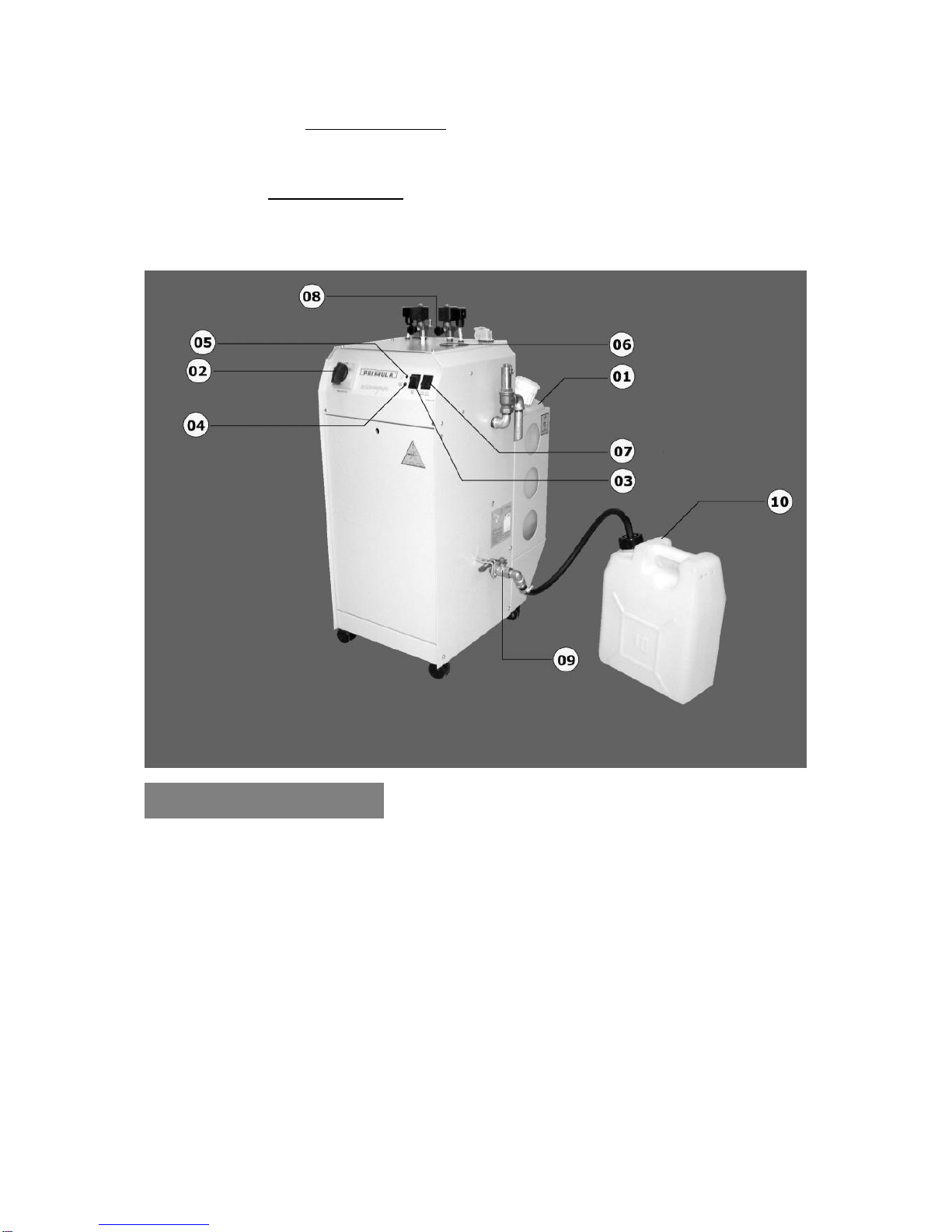
If the pump is ordered to feed water in very short periods & steam draining is
appeared in the feed-water tank No 1, check the one way valve No29:Clean or
replace it , by paying attention on putting it back in the correct direction.
Maintenance
Troubles shooting

8
SAFETY VALVE
If it remains open –the manometer No 06 shows over 3,5bar.Check the pressure
switch pressure adjustment. Adjust it at max. 3,5bar. In case it continues
increasing,please replace the pressure switch No 15.
Technical Assistance
For any advice about the operation of the machine or the spare parts, please contact
our agents in your territory------------------------------------------------------------------------------
------------------------------------------------------------------------------------------------------------------
------------------------------------------------------------------------------------------------------------------
-------------------------------------------------
or directly us.
Adress: 14th kms National Road of Thessaloniki – Kilkis, P.C. 57200
TEL. +30 23940 71215, FAX: +30 23940 71438
www.primula.gr – e-mail:info@primula.gr
-Specifications may be subject to change without prior notice.

9

10
Steam generator mod. Ecovapor - Spare parts list
Pos.
Articel nr.
Designation
1
303-03-041
Feedwater tank 25lt
2
303-03-031
Cover of main switch
3
308-00-006
Switch ON-OFF 16A
4
303-06-004
Control lamp red (LED)
5
303-06-004
Control lamp red (LED)
6
303-03-007
Manometer
7
302-00-017
Double switch ON-OFF
8
303-03-031-1
Axel of main switch 3X25
9
303-03-026
Blow-down valve 1/2"
10
303-03-039
Blow-down tank 5 lt
11
308-00-004
Corner of solenoid steam valve
12
193-06-012
Pressostat’s coil
13
303-06-013
T 1/4"-1/4"-1/4"
14
193-06-014
Manometer’s coil
15
303-03-014
Pressostat
16
193-06-016
Electrode
17
193-06-017
Pipe of safety valve 1/2”
18
303-06-018
Feedwater tank’s lid
19
303-03-057
Corner 1/2” (Female -Female)
20
193-06-020
Condensate’s pipe
21
303-03-002
Water pump 0,5HP PkM60
303-06-002-2
Water pump 0,7HP PKM65 (for model 4.5bar)
22
193-06-022
Boiler
23
303-03-003-15
Heating element 2500W/230V
303-03-003-11
Heating element 4000W/230V
303-03-003-9
Heating element 4000W/4000V
303-03-003-10
Heating element 6000W/400V
24
303-06-024
Metallic flange of heating element
25
303-06-025
Heating element’s screw
26
193-03-004
Seal heating flange
27
193-03-013
Water’s copperpipe 1/2" (New model)
28
303-06-028
Nipple 1/2"
29
303-03-016
One-way valve 1/2"
30
303-03-018
Solenoid water valve 3/8” 9313
31
303-06-031
Nipple 1/2" X 3/8”
32
303-06-032
Electronic PC board
33
303-06-033
Fuse 25A of heating element
34
303-03-032
Relay of heating element
35
302-03-038
Main switch 3X25Amber
36
308-00-003
Valve’s plug

11
37
303-03-010
Solenoid steam valve 9934
38
308-00-002
Coil of solenoid steam valve 9934
39
303-03-021
Female plug-4 poles ILME
40
303-03-011
Safety valve 1/2” BETA
41
303-03-017
Corner 1/2” (Male-Female)
42
193-06-042
Pipe of safety valve 1/2” BETA
43
300-00-119
Contraction 1" x 1/2" (Male-Female)
44
303-03-023
Nipple 1/2” X 12
45
303-03-027
Corner 1/2” (Male-Female) of blow-down valve
46
193-06-046
Water-feed tank’s base
47
303-03-025
Power feeding cable 3X2,5mm2with Shuko plug
303-03-025-1
Power feeding cable 5X2,5mm2
48
303-06-048
Gland
49
303-03-029
Double wheel
50
300-00-040
Shuko plug
51
303-03-045
Clamp 10-16
52
303-06-056
Outlet hose

12

13

14
WIRING DIAGRAM – STEAM GENERATOR ECOVAPOR
Symbol
Code
Description
SW1
302-03-038
Main switch 3X25A
K1
303-03-032
Relay for heating 25A-230V
K2
303-03-036-3
Relay for pump 30A on the Electronic circuit card typ.903
RE
303-03-003-15
Heating element 2500W/230V
303-03-003-11
Heating element 4000W/230V
303-03-003-9
Heating element 4000W/4000V
303-03-003-10
Heating element 6000W/400V
PS
303-03-014
Pressostat
PF1
303-03-021
Socket plug for iron No 1
PF2
303-03-021
Socket plug for iron No 2
E/V1
303-03-018
Solenoid water valve 3/8” 9313
E/V2
303-03-010
Solenoid steam valve No 1
E/V3
303-03-010
Solenoid steam valve No 2
PM
303-03-002
Water pump 0,5HP PkM60
303-06-002-2
Water pump 0,7HP PKM65 (for model 4.5bar)
E1
303-06-016
Water level electrode
PCB
303-06-032
Electronic circuit card -all functions control ,typ ECO 903
CV
303-03-025
Cabel of power supply 3X2,5mm2
F1/F2
303-06-033
Automatic fuse 32A (for models 230V)
F1/F2/F3
303-06-033-2
Automatic fuse 16A (for models 400V)
F1/F2
303-06-033-1
Automatic fuse 32A (only for models 2.5KW-230V & 6KW-400V)
F3
303-06-033-2
Automatic fuse 316A (only for models 6KW-400V)

15
This manual suits for next models
3
Table of contents
Other Primula Iron manuals