Priority Electric Transportation PET PRO-FLEX 500 User manual

US Patent 0540, 400
Other Patents Pending
Read this manual
completely before
assembling and riding
our PET PRO-FLEX
500
Always wear a
Helmet!
Priority Electric Transportation, LLC.
1007 West College Ave. #293
Santa Rosa, CA 95401
Phone# 707-521-9257
Sales –Dennis Vickrey @707-393-0724
dennisvickrey@yahoo.com
Admin –Michael Ringstad 707-396-8876
ringmichael48@yahoo.com

Table of Contents
Technical Information----------------------------------- 1
Warning Statement ------------------------------------- 2
Read Before Riding-------------------------------------3
List Of Parts ---------------------------------------------- 4
Front Bar -------------------------------------------------- 6
Tool Kits InThe Tool Bag------------------------------7
Assembling The Pro Flex 500 ---------------------- 8
Charging The Batteries------------------------------ 12
Riding The Pro Flex 500 ---------------------------- 13
Folding The Pro Flex 500 ----------------------------15
Maintenance---------------------------------------------17
Wiring Diagram ---------------------------------------- 18
Trouble ShootingGuide ----------------------------- 20
Warranty---------------------------------------------------22

1
Technical Information Pro Flex 500
Model No.
PET PRO-FLEX 500
Product size
40 L x 27 W x 38 H inch
(102 L x 68 W x 98 H cm)
Type of motor
Permanent-magnet
brushless DC wheel motor
Motor power
Wheel motor
36 V 350 W / 48V 500W
Battery type
sealed lead acid battery
Battery capacity
36 Volt 12Ah / 48V 12Ah
Charger
110V-240V, UL approved
Charging time
4-6 hours
Max. speed
Up to 13 MPH ( 22 km/h)
15 MPH ( 25km/h)
Single charge
Up to 17 MILES (28 km)
20 MILES (32km)
Max capacity
299 LBS (136 kg)
Net weight
101 LBS (46 kg)
112LBS (51kg)
2
Warning Statement PRO
FLEX 500
Do
not
ri
de
thi
s
scooter
unti
l
you
read
and
thoroughl
y
understand
the
owner's
manual
I
t
contai
ns
i
nformation
cri
ti
cal
to
your
safety.
I
f
you
have
questi
ons
about
the
operati
on
of
this
scooter,
you
should
consu
l
t
your
authori
zed
dealer
.
It
is
extremel
y
i
mportant
that
you
follow
the
safety
guidel
i
nes
contained
i
n
thi
s
manual
in
order
to
insure
maximum
safety.
Failuretocomplywiththestandardsoutlined
in
this
manualcouldresultinfire and/or seriousinjury.
ZAP
is
notliablefor anydamage or injuriescaused
byunsafeorfaulty repairs. Any repairsmadetothis
productbyunauthorizedservicetechniciansarethe
soleresponsibilityoftheowner.
Our productsaredesignedtobeecologically
conscious,pleasedisposeofusedbatteries
in
compliancewithlocallaws.
O AN
operate
DE
CONTACT
TO DETERMI

3
Read BeforeRiding PET
PRO-FLEX 500
WARNING
THE ELECTRIC PET PRO FLEX 500 IS NOT A TOY AND
SHOULD
NOT BE OPERATED BYANY ONE UNDER 12
YEARSOLD.
Safety Instruction
(Please take note of the followings before each ride)
•
The maximum weight capacity is 299 LBS.
•
Only one person at a time should ride.
•
Always wear protective gear including knee and
elbow pads and an approved safety helmet when
riding the Pro Flex 500
•
Before riding besure to check that all pivot points,
locking buttons, quick releases, and latches are
secured properly.
•
The power switch lock must be inthe "off' position
when the Pro Flex 500
is
being charged.
•
Do not use the Pro Flex 500 when it is raining.
•
Do not place the battery near heat or fire.
•
Donotexpose the charger to water or any moisture.
•
Check ifbattery
is
properlycharged andinstalled.
•
Charge battery after each use.
•
Always ride on dry paved surfaces. Gravel, wet and
uneven surfaces are a hazard.
C
heck
if
all
tires
are
prope
rly
infla
t
ed
.
4
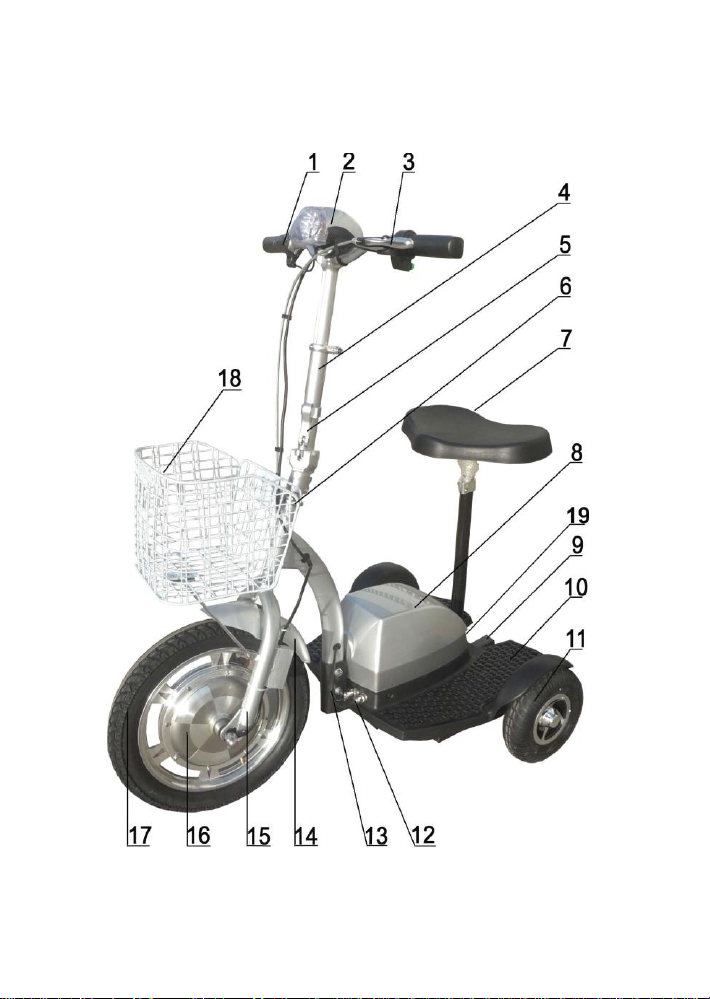
LIST OF PARTS PET PRO FLEX 500

5
List
Of
Parts
PET
PRO-FLEX
1 Throttle
2 Multi-function Instrument
3 Brake lever
4 Alloy handlebar tub
5 Quick release
6 Connecting tube
7 Seat
8 Battery & controller compartment
9 Balancing wheel
10 Footboard
11 Rear wheel
12 Power connecting plugs
13 Allen set screw
14 Front fender
15 Front fork
16 Motor
17 Front wheel
18 Basket
19 Charger port
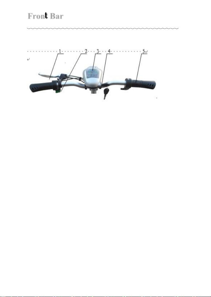
Front
Bar
6
PET
PRO-FLEX
500
1 Brake lever
2 Horn switch
3 Multi-function Instrument
4 Key switch
5
Throttle
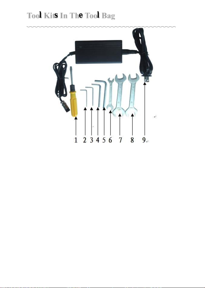
7
Tool
Kits
In
The
Tool
Bag
PET
PRO-FLEX
1 Screwdriver
2 Allen wrench (2.5mm)
3 Allen wrench (3mm)
4 Allen wrench (5mm)
5 Allen wrench (6mm)
6 Wrench (8 x 10mm)
7 Wrench (16 x 18mm)
8 Wrench (16 x 18mm)
9 charger
8
Assembling
The
Pro Flex 500
PET
PRO-FLEX
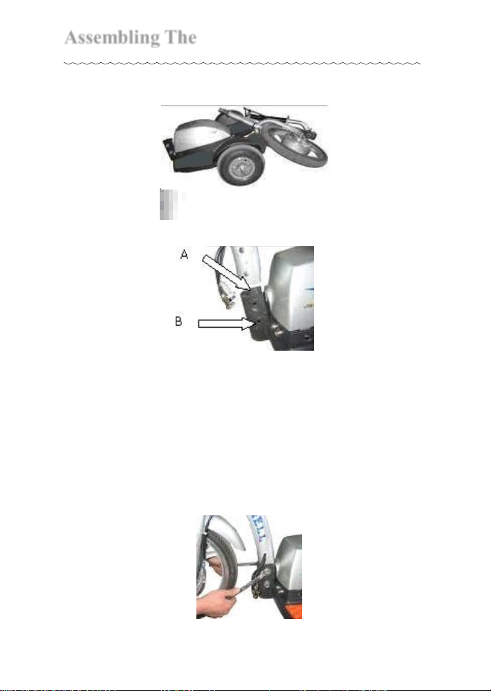
1. Unpack the Pro Flex 500carefully so that
youdo not misplace any of the parts.
2. Place the Pro Flex 500 on a flat, levelsurface.
Block the front up 3.5''. This will make thenext
step easier
3. Remove the bolts and nuts from the
connecting tube clamp (B). Place the
connecting tube into the top opening (A).
After aligning the holes, place the twobolts
through the connecting tube and neck
assembly. Twist the bolts, do not hammer
them through.
Tighten these two bolts withthe
nuts provided.
9
Assembling
The
Pro Flex 500
PET
PRO-FLEX
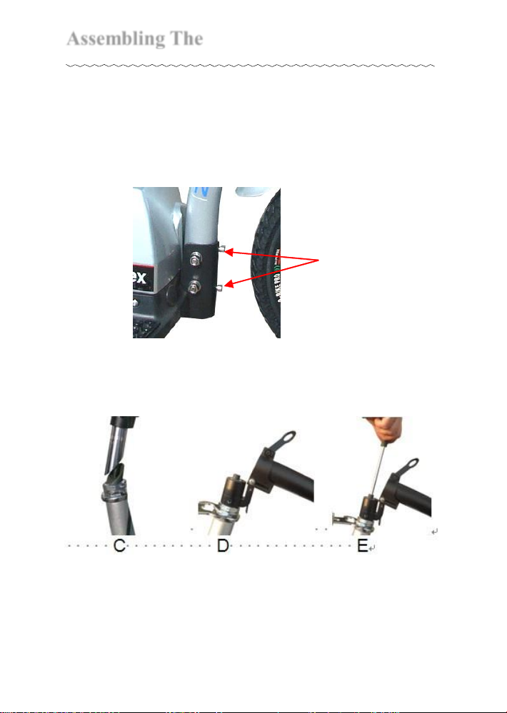
4. The two Allen set screws on the front of the
connecting clamp are for removing any play
after the bolts have been tightened. First, back
off the nuts, second, set the screws, third,
tighten the nuts to prevent the screws from
backing off.
Two Allen
set screws
5. Extend the handle bar tube to full upright
position, and slide it into connecting with the
front fork.
10
Assembling
The
Pro Flex 500
PET
PRO-FLEX
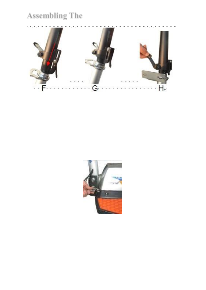
7. Ensure that the handlebar is facing front, the
brake on the left side and the throttle onthe
right, then tighten the handlebar tube collar
clamp using the enclosed 5mm wrench
8. Plug in the two power connecting plugs into
the sockets. The design of each plug and
socket is different. Connect the ones which
best fit each other to finish the assembly.
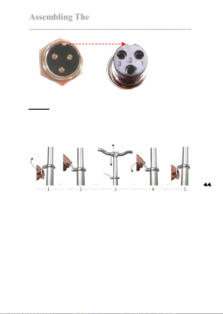
9.
Match the pins of the plugs to the holes of the
sockets. Note the alignment notches.
11
Assembling
The
Pro Flex 500
PET
PRO-FLEX
NOTE: Handle bar height adjustment. Handle
bar height can be easily adjusted by openingthe
quick release on the handlebar tube topreferred
height, then firmly closing quickrelease.
12
Charging
The
Batteries
PET
PRO-FLEX
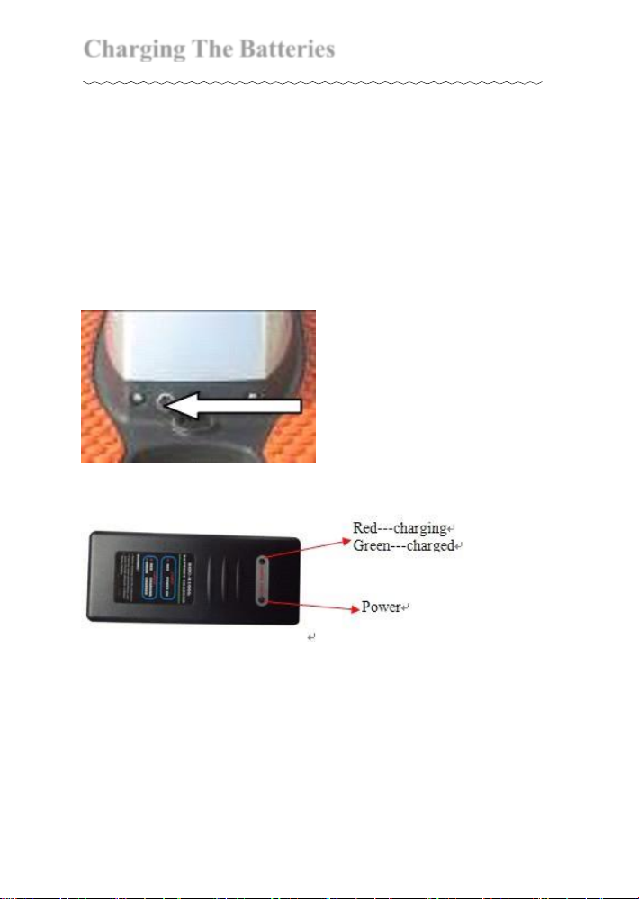
●Before you ride the Pro Flex 500 for the first time
you must charge the batteries for 4-6 hours using
only the suppliedcharger.
●Tocharge the batteries, plug the charger into the
charger socket located on the rear side of the
battery/ controller compartment. Then plug the
charger into a wall outlet.

13
Riding
The
Pro Flex 500
PET
PRO-FLEX
●Once you have completed the initial charge you
are ready to ride. Remember, this is not a toy. The
PET PRO FLEX 500can reach speeds up to 17
mph / 20mph depending on the terrain and the
weight of the rider. You must wear a helmet and
protective pads. Be aware of all local laws and
ordinances that govern and/or restrict the use of
poweredscooters. The laws and ordinances vary
greatly from municipalitytomunicipality. It is your
responsibility to know and abide by your local
restrictions.
●To ride, plug the key into the key switch andturn
the key in clockwise direction till the first click.The
battery gauge will be illuminated indicatingthat the
battery is in operation. If you want to turn on the
front light, please turn the key to the second click
in clockwise direction.
●Hold onto the front bar with both hands.Your
left fingers will control the brakes and yourright

14
Riding
The
Pro Flex 500
PET
PRO-FLEX
hand will control the throttle. As you turn the
throttle towards yourself, the speed will be
increased. Release the throttle and applythe
brake to stop the scooter. You will control the
speed of the scooter by using both thethrottle
and the brake. When the brake handle is
squeezed it cuts power off thethrottle.
NOTE 1: WARNING: Never try stunts . Always
maintain a safe speed.
NOTE 2: When scooter is parked, please turn off
the power and take off the key, this will avoid
anyone from accidentally turning the throttle
causing the scooter to speed forward. Failure to do
this could lead to an accident.
NOTE 3: If you need to stop in an emergency or
kill power quickly, you can turn the keyoff.
15
Folding
The Pro Flex 500
PET
PRO-FLEX
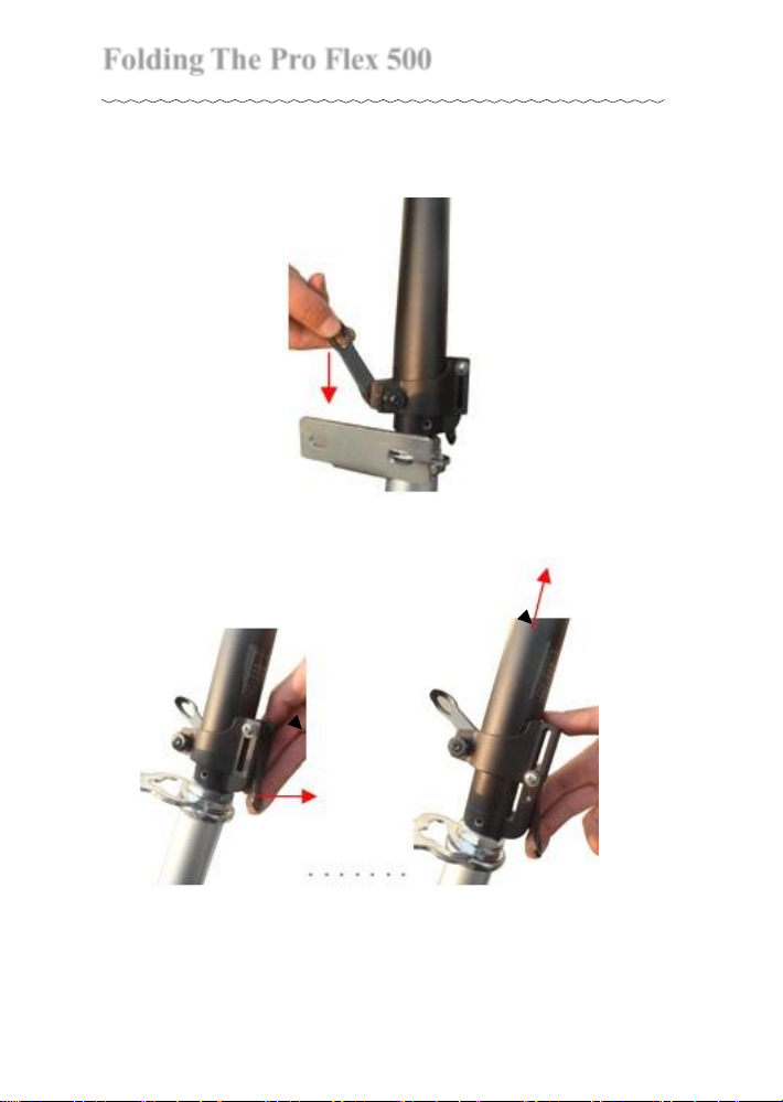
1. Turn off the key switch
2. Press the quick release to bottom.
3. Lift the clip bar, at the same time pullthe
handlebar tube.
16
Folding
The Pro Flex 500
PET
PRO-FLEX
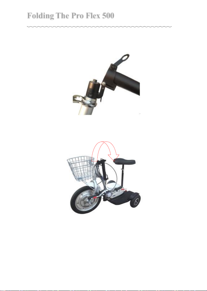
4. Lift the connecting tube (which is also
attached to the handlebar tube).
5. Carefully place the handlebar tube on the
footrest frame

17
Maintenance
PET
PRO-FLEX
Battery: (for professional useonly)
The PET Pro-Flex is powered by four 12 volt,
rechargeable batteries housed in a single
compartment. Other than recharging, these
batteries need no maintenance. To prolong battery
life, recharge the battery after eachuse. You must
also charge your PET Pro-Flex if it has not been
used for 30 days or more. If you need to replace
the battery pack, it is located inside the battery
compartment on the footboard. To get to the
battery pack, remove the compartment cover by
loosening the screws. To
remove the batteries
disconnect the wires from the battery terminals.
Replace the battery pack with a new one and
reconnect the wires. Follow the instructions on
charging batteries to charge the new batteries.

18
Wi
r
ing
Dia
g
r
am
PET
PRO-FLEX
i'Jr+
Table of contents


