Prism Medical SA-200 User manual

Introduction......................................................................2
Overview..........................................................................2
Components of the Stand Aid..........................................3
Component List ...............................................................4
Specifications ..................................................................5
Cautions ..........................................................................6
Assembly Instruction ......................................................7
Operation
Charging...……………………………………………...12
Start……...……………………………………………...12
Forward movement….………….……………………..13
Turning..………………………………………………...13
Leg Adjustment………………………………………...14
Raising and Lowering Boom………………………….14
Castors and Braking……….……………………….....14
Basics in transferring an individual…………………...….15
Emergency Stop & Lowering……………………………..17
Control Box-Usage Information………………….…….....18
Control Box-Service Information….....………………......19
Technical Specifications ……………………………….....20
Do’s and Don’ts ……………………………………….…...21
Fault finding……………………………………….………..22
General inspection and maintenance………..…………..23
Points of Attachment - Checklist …………….…………..24
Service record history……………………………..……....25
Warranty……………………………………………..……...29
Prism SA-200
Aluminium Stand Aid
Owner’s Manual
Use and Care
Trouble Shooting
Warranty Information
Prism Medical UK
Unit 4 Jubilee Business Park
Jubilee Way
Grange Moor
Wakefield
WF4 4TD
Tel: 0845 409 2000
Fax: 0844 980 2261
Website: www.prismmedical.co.uk

Page:2 Rev:04.2014 SA‐200‐Owner’sManual
Copyright Prism Medical UK 2014
CAUTION: DO NOTATTEMPT TO USE THIS EQUIPMENT
WITHOUT FIRST UNDERSTANDING THE CONTENTS OF
THIS MANUAL.
Introduction
Overview of Prism SA-200 Stand Aid
Before using this equipment, and to ensure the safe operation of your Prism SA-200 Stand Aid, carefully
read this entire manual, especially the section on “Cautions”. The SA-200 is designed to be used in
conjunction with Prism Medical UK accessories and slings. Please refer to any user guides supplied with these
components and refer to them while reviewing this manual.
Should any questions arise from reviewing this manual contact your local authorised Prism Medical UK
representative. Failure to comply with warnings in this manual may result in injury to either the operator, or
the individual being lifted/transferred. Damage to the Stand Aid and/or related components may also occur. Be
sure that the contents of this manual are completely understood prior to using this Stand Aid.
Store this manual with the documents included with the stand aid and sling (s). Contents of this manual are
subject to change without prior written notice.
The Prism SA-200 Stand Aid is a lifting aid used by health care professionals to transfer clients. The Stand
Aid makes it possible to move mobility impaired individuals with minimal strain or risk to the caregiver, while
providing complete safety, dignity and comfort for the client.
The Prism SA-200 Stand Aid is one of two components that make up this technology. The other component,
the sling, is a specially designed fabric accessory that attaches to the stand aid by means of a sling hook and
straps, and holds an individual while the lift, or transfer takes place. The sling is generally supplied with the
Stand Aid at the initial time of purchase. Please refer to any user guides supplied with the sling and reference
them while reviewing this manual.
The Prism SA-200 Stand Aid has the ability to stand an individual up from one location such as chair, then
move the individual to another location and finally lower the individual into a wheelchair. The functions of
lifting up or down are accomplished by pressing buttons on the hand control. The hand control is attached to
the Stand Aid. Due to the design of the Stand Aid system, it takes very little effort to press a button to perform
the desired motion.
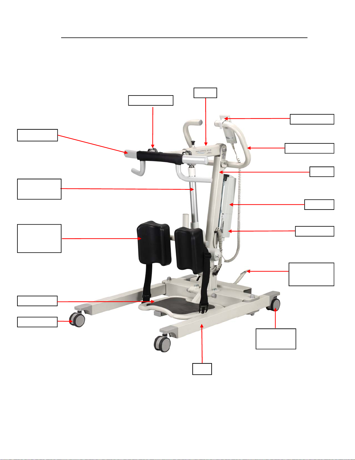
Please familiarise yourself with the components of the Prism SA-200 Stand Aid by referring to the diagram
on the next page.
Model Table for Prism SA-200 Stand Aid
Product Code Product Description
SA-200 SA-200 - Aluminum Stand Aid 200 Kgs
SA‐200‐Owner’sManual Rev:04.2014Page:3
Copyright Prism Medical UK 2014
Sling Bar
Boom
Push Handle
Battery
Up & Down
Actuator
Mast
Hand Control
Control Box
Front Castor
Leg
Rear Castor
With Brake
Foot Pedal for
Leg Spreading
Foot Plate
Knee Pad
with
Calf Strap
Sling Hook
Components of the Prism SA-200 Stand Aid

Page:4 Rev:04.2014 SA‐200‐Owner’sManual
Copyright Prism Medical UK 2014
The following components are included with your new Prism SA-200 Stand Aid system:
• Prism SA-200 Stand Aid
• Hand Control
• Stand Aid Integrated Charger
• Mains Charger Cable
• Owner’s Manual
• Multi Function Spanner
• 5 mm Hex Allen Key (Short Arm)
• 4 mm Hex Allen Key (Short Arm)
• 3 mm Hex Allen Key (Short Arm)
SLINGS: If a sling has been supplied with the Stand Aid, then please refer to the instructions included
with the sling.
IMPORTANT: Before initial use, the Stand Aid unit must be charged for 4 to 5 hours. Refer to section
titled “Charging Instructions”. The Hand control must also be connected to the Stand Aid. If it is not
connected, then please refer to the section titled “Assembly Instructions”.
Component List

SA‐200‐Owner’sManual Rev:04.2014Page:5
Copyright Prism Medical UK 2014
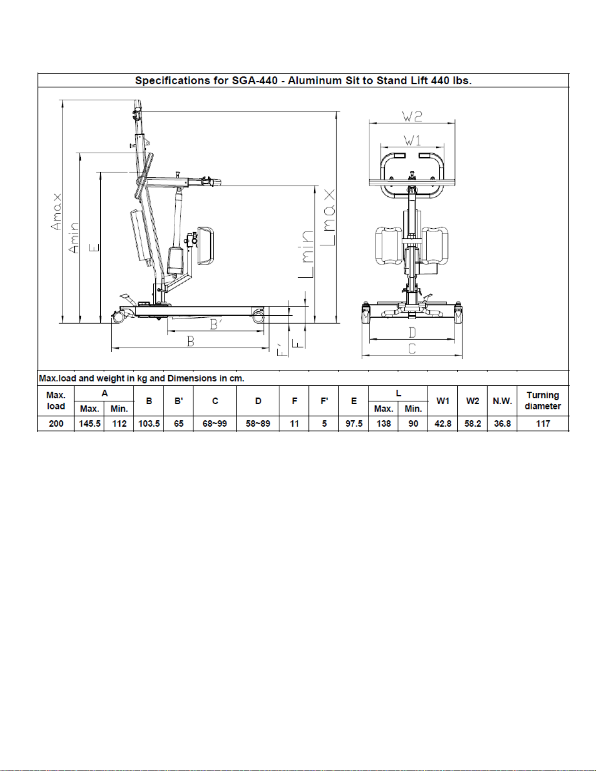
Technical Specifications– SA-200 Stand Aid
(A) Dimensions and Weight - SA-200 Stand Aid
Specification SA-200
Maximum weight capacity 200 kg (31.5 Stone)
Maximum lifting height 138 cm
Minimum lifting height 90 cm
Height to top of legs 11 cm
Clearance from bottom of legs to floor 5 cm
Overall length 103.5 cm
Distance inside the legs (min.) 58 cm
Distance inside the legs (max.) 89 cm
Distance outside the legs (min.) 68 cm
Distance outside the legs (max.) 99 cm
Turning radius 117 cm
Wheels (dual-wheel castors) Front –76 mm
Rear – 76 mm with brake
Weight of Stand Aid 36.8 kg
Total Shipping Weight with Box 43.83 kg
Lift Motor: 24 VDC, 10.5 Amps Max.
Charger Input: 100-240 VAC, 50-60 Hz, 0.4 Amps Max.
Charger Output: 24 VDC, 0.65 Amps
Batteries: 24 VDC (2 x 12 VDC) 2.9 Ah, Sealed Lead Acid
Hand Control: Electric
Lifting Range: 900mm to 138mm
Stand Aid Weight: 36.8 Kg
Maximum Load: 200 Kg (31.5 stone)
Duty Cycle: 10% use, 90% rest
Rated Performance: 30 lifts at 440 lbs., 10% duty cycle.
Maximum load of the installed Stand Aid is determined by
referring to the product label located on side of the Stand Aid
Shipping/Storage Conditions:
Temperature: -40 to +70 ºC
Relative Humidity: 10 to 100% RH
Atmospheric Pressure: 500 to 1060 hPa
(B) Electrical Specifications - SA-200 Stand Aid
Normal Operating Conditions:
Temperature: +10 to +70 ºC
Relative Humidity: 30 to 75% RH
Atmospheric Pressure: 700 to 1060 hPa
, Class 2, IPX4
, IPX4

Page:6 Rev:04.2014 SA‐200‐Owner’sManual
Copyright Prism Medical UK 2014
●Under no circumstance should the Prism SA-200 Stand Aid and slings be put in control of a per-
son who has not been properly trained in the use and care of this equipment. Failure to adhere to this
warning may result in serious injury to the operator, and/or the individual being lifted/ transferred.
●The Prism SA-200 Stand Aid and slings are not toys. Do not use it for unsafe practices. Do not
allow children to play with the Stand Aid or any of its components.
●The manufacturer's warranty is voided if persons unauthorised by Prism Medical UK perform work
on the Prism SA-200 Stand Aid.
●There are no user serviceable parts inside the actuator. Do not remove cover screws, or open the
unit, as this will VOID THE WARRANTY.
●In facilities where more than one operator will be responsible for using the Prism SA-200 Stand
Aid and sling (s), it is imperative that all such members are to be trained in its proper use. A training
programme should be established by the facility to acquaint new operators with this equipment.
●Never expose the Prism SA-200 Stand Aid directly to water. Warranty does not cover any misuse
or abuse of the Stand Aid system.
●To maintain optimum function, the Prism SA-200 Stand Aid should be inspected and maintained
on a regular basis. See the section titled “General Inspection and Maintenance”.
●Any accessories used with the Prism SA-200 Stand Aid including sling (s), should be checked to
ensure that they are in good working order. Check for signs of wear or fraying prior to use. Report any
unusual wear, or damage immediately to your local authorised Prism Medical UK Service Provider.
●The Prism SA-200 Stand Aid and associated slings are intended only for lifting and transferring
of a person. Prism Medical UK will not be responsible for any damage caused by the misuse, neglect
or purposeful destruction of the Stand Aid, and/or its associated components.
●In any circumstances do not exceed the maximum allowable load of this Stand Aid. Refer to the
“Specifications” section of this manual, and/or the labels on the side of the Stand Aid.
●There is a risk of explosion if the Stand Aid is used in the precsense of flammable anaesthetics.
●Ensure that a clear space is maintained around the Stand Aid. Move any obstacles out of the way
before operating the Stand Aid.
Cautions:
SA‐200‐Owner’sManual Rev:04.2014Page:7
Copyright Prism Medical UK 2014
Assembly Instructions:
1. Place the Carton/Packaging box in a clear working area, open carefully, and remove following items and
place on the floor, taking care to protect the finish from damage.
Mast with Boom assembly
Base Assembly with Legs attached
Battery Pack, Control Box and Charging Power Cord
Hand Control
Tool Kit
User Manual, and Test Certificate
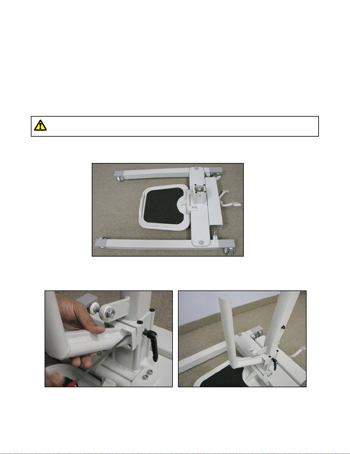
2. Place the Base assembly with legs attached on the floor, and lock both rear castors as shown in Figure 1.
3. Mount Knee Pad Height Adjustment Rod using four screws supplied with the Stand Aid as shown in Fig-
ure 2, and 3.
Caution: Component parts are heavy, and will need to be lifted with care.
Heavier items may need two people for assembly.
Figure 1
Figure 2 Figure 3

Page:8 Rev:04.2014 SA‐200‐Owner’sManual
Copyright Prism Medical UK 2014
Assembly Instructions:
4. Place the Mast with Boom assembly upright in the tube on the Base assembly as shown in Figure 4. Using
Locking Handles, secure the mast in the desired position on the base as shown in Figure 5. Adjust the
position of the locking handles pointing in downward direction towards the base as shown in Figure 4.
5. Route the Lifting Actuator Cable assembly as shown in the Figure 6.
Locking Handles
Figure 4
Caution: Possible finger trap. Keep fingers away from the end of the mast when inserting into
the tube on the Base assembly. Heavier items may need two people for assembly.
Lifting Actuator is not shown in the figure below.
Figure 5
Figure 6
SA‐200‐Owner’sManual Rev:04.2014Page:9
Copyright Prism Medical UK 2014
Assembly Instructions:
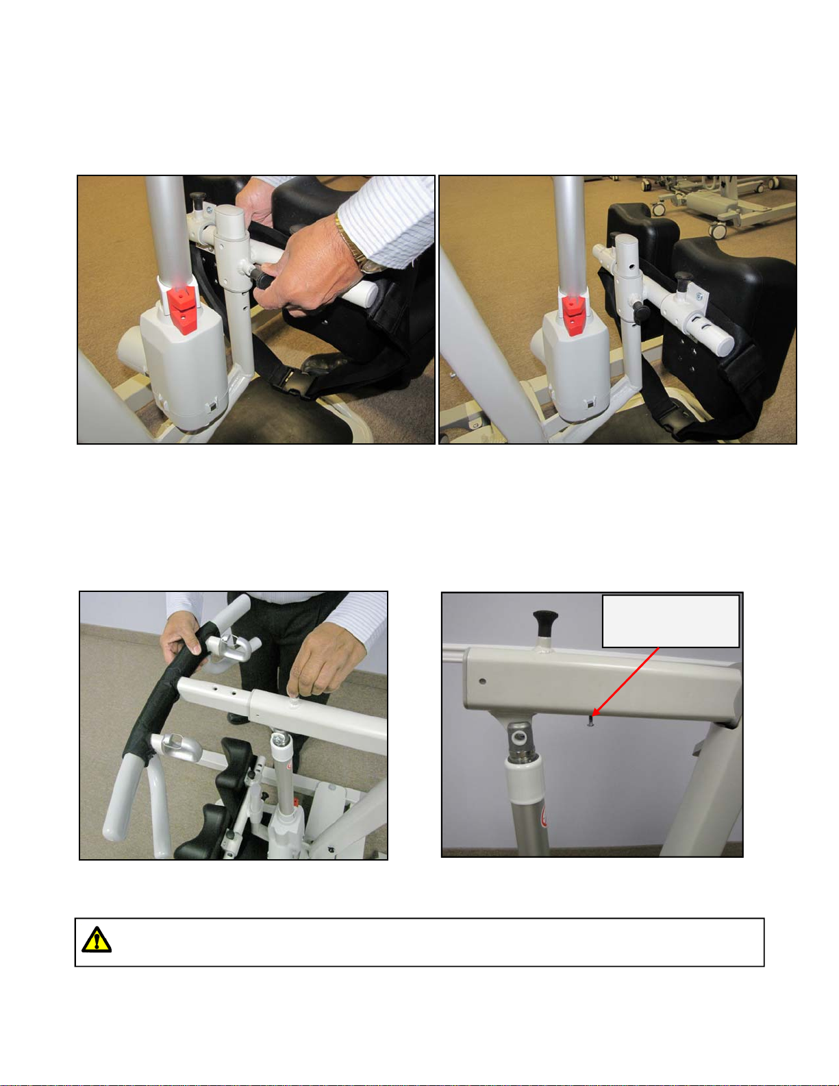
6. Pull the plastic knob to insert the Knee Pad Assembly into the Knee Pad Height Adjustment Rod and
release the plastic knob once it aligns with hole on Knee Pad Height Adjustment Rod as shown in Figure 7,
and 8.
7. Insert the Sling Bar into the Boom of the Stand Aid by pulling plastic knob on top of the boom as shown in
Figure 9. Make sure that the sling bar locking screw is out from the boom as shown in Figure 10. After
inserting the sling bar, tighten the sling bar locking screw so that sling bar secured into the boom.
Figure 7 Figure 8
Figure 9 Figure 10
Caution: Sling bar locking screw must be tight, and locked for all the times.
Failure to do so, may result in severe injury.
Sling Bar
Locking Screw
Page:10 Rev:04.2014 SA‐200‐Owner’sManual
Copyright Prism Medical UK 2014
Assembly Instructions:
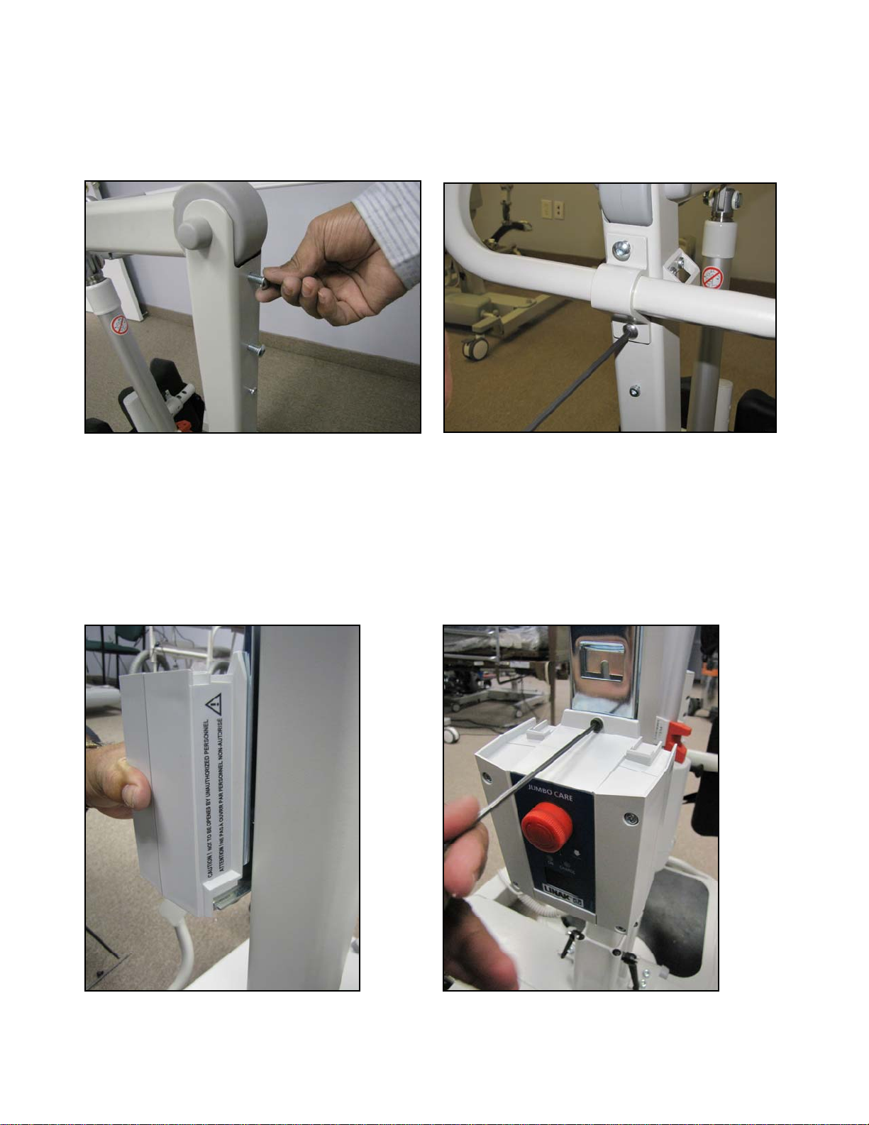
8. Remove the screws from the mounting position of push handle on Mast assembly as shown in Figure 11.
Insert the screws through the push handle bracket, and mount the push handle on the Mast Assembly as
shown in figure 12.
9. Remove the middle screw from the mounting bracket using 3 mm Allen Key. Press the SA-200 CBJ Care
Control Box against the mounting bracket and slide it down. The control box should be seated securely on
top of the edge of bracket as shown in Figure 13. Mount the Control Box to the mounting bracket using
same screw that you removed from the middle of the bracket as shown in Figure 14.
Figure 11 Figure 12
Figure 13 Figure 14

SA‐200‐Owner’sManual Rev:04.2014Page:11
Copyright Prism Medical UK 2014
Assembly Instructions:
10. To install the battery, you will need to press the battery against the bracket and slide it down until it sits
straight on top of the control box as shown in Figure 15. Make sure to secure the battery box by latching
the battery lock into the bracket as shown in Figure 16.
11. Connect all the cables to the control box as shown in the Figure 17 to 19.
A. Connect the Hand Control connector to the large circle on the left side of the control box as shown in
the Figure 17.
B. Connect the Up/down Actuator Cable connector to the second circle (Marked No. 1) from the left side
of the control box as shown in the Figure 18.
C. Connect the Mains Power Cord to the rectangular outlet on the control box as shown in the Figure 19.
12. Please make sure to charge battery before initial use and before each operation of the Stand Aid.
Figure 15 Figure 16
Figure 17 Figure 19Figure 18
After assembly, check to ensure that:
1. The mast is fully locked into position.
2. The RED emergency stop button on control box is in the OFF (out) position.
3. Lifting actuator is moving up and down with the buttons on the hand control, and control box.
4. Emergency lowering (mechanical, and electrical) function works properly.
5. Rear wheel brakes works properly.
6. Leg spreading foot pedal works properly.
7. Battery is fully charged.
Page:12 Rev:04.2014 SA‐200‐Owner’sManual
Copyright Prism Medical UK 2014
Operation:
Charging:
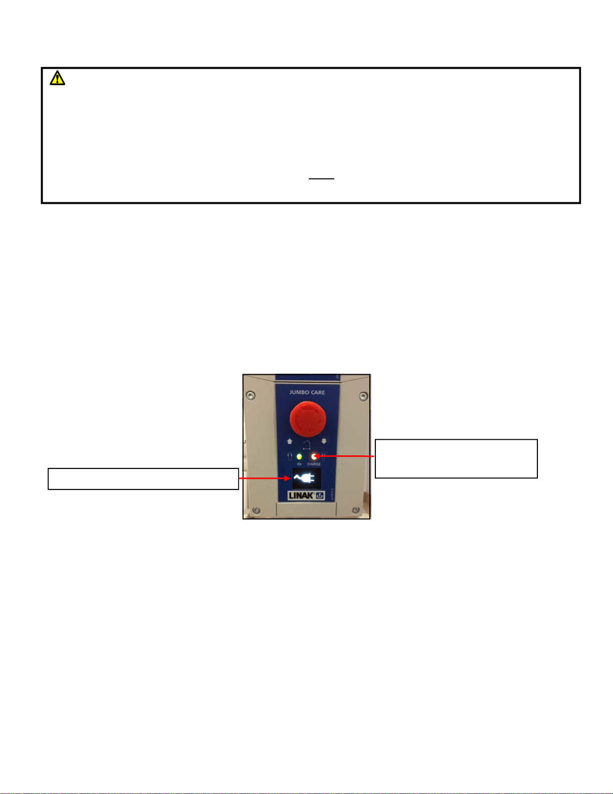
The “On” light illuminates when you plug the control box to the power outlet and should turn off when it is
unplugged. The “Charge” light illuminates, and when you connect the battery to the control box and it is
charging, also the LCD displays shows the symbol of mains cable plug in as shown in the Figure 20. The
“Charge” light will turn off when the battery is fully charged.
The Stand Aid should be plugged in for charging whenever it is not in use to get the max number of cycles out
of the battery. An audible battery alarm will sound when approximate 25% of battery capacity
remaining. To obtain max life, charge the battery at no more than 30% discharge.
Please Note: The battery can be charged whether the Emergency Stop is activated or not.
Start:
The Hand Control has two functions up and down. Press down on the symbols to operate the desired function.
It is not possible to use two functions at the same time.
An audible alarm will sound once the load becomes too great on the Stand Aid. This will cause the lifting
operation to stop. Do not continue to operate the handset by repeatedly pressing the buttons. At this point the
Stand Aid has reached it's maximum lifting capacity. This is a purposefully built in safety feature.
Please Note!
The emergency stop must be released at all times during normal operation.
Caution: Visually inspect the Stand Aid before using for any unusual wear and tear. Should
anything look unusual then contact your local representative prior to use.
Failure to comply with this caution could result in serious injury to the operator, the individual being
lifted and/or damage to the Stand Aid.
Because of the safety function in the actuator the lifting arm and hanger bar can “fall down” to the
height of the spindle. Therefore, both before and after each lifting operation, press the lifting arm down
to ensure that it is supported by the actuator. This must be done, to remove the possibility of the lifting
arm “falling down” and the risk of subsequent injury occurring.
Charging Indicator Light ON
when the unit is charging
Display shows Mains Cable Plug in
Figure 20
SA‐200‐Owner’sManual Rev:04.2014Page:13
Copyright Prism Medical UK 2014
Operation:
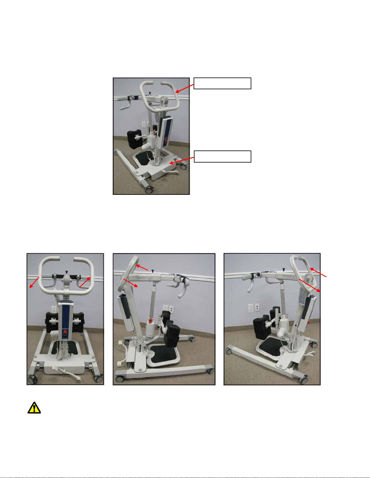
Forward Movement:
To move the Stand Aid forward, hold onto the handle bar and push forward. Alternatively, the
caregiver can also place one foot on the base tube and push forward with their foot.
Turning:
When turning the Stand Aid, stand on along one side. With one hand pull gently on the handle bar,
and with the other hand push gently away on the lifting arm. In this way the Stand Aid will rotate
around its own axis. This movement is performed with a smooth, slow action to avoid swinging the
patient unnecessarily.
HANDLE BAR
Warning:
Do not hold on to the actuator when turning the Stand Aid as there is a risk of damaging the actuator.
BASE TUBE
Page:14 Rev:04.2014 SA‐200‐Owner’sManual
Copyright Prism Medical UK 2014
Leg Adjustment:
The legs of SA-200 Stand Aid are mechanically adjustable for opening, and closing base width. The legs can
be opened to enable access around arm chairs or wheel chairs. For transferring through narrow doorways, and
passages the Stand Aid legs should be in closed position.
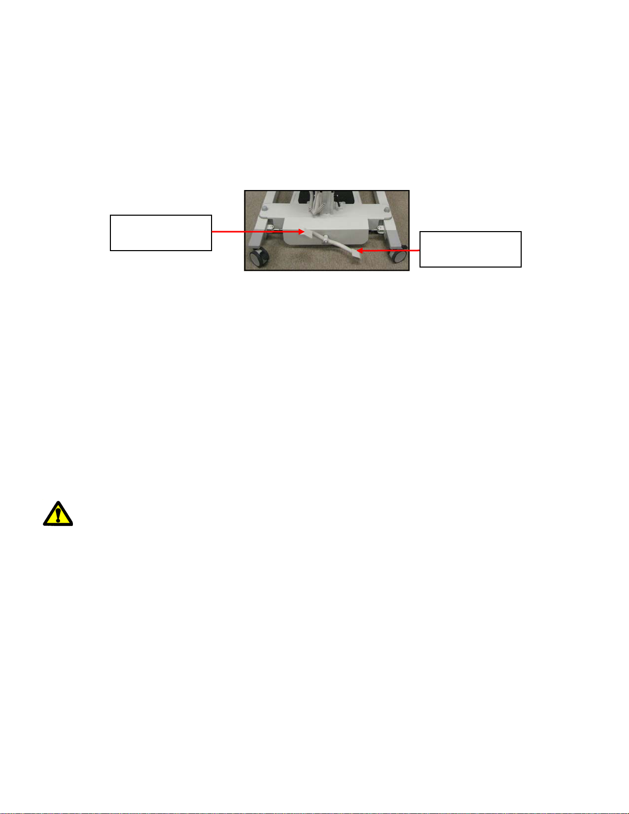
Leg adjustment is achieved by pressing the foot pedal located at the rear of base. To open the legs, press down
the left side, and to close the legs press down the right side as shown below.
Raising and Lowering the Boom:
The up and down movement of boom on SA-200 Stand Aid is achieved by a powerful electric actuator which
is controlled by hand control. The hand control has two buttons with directional arrows UP and DOWN.
The actuator stops automatically at the limit of travel in both directions.
Castors and Braking:
The SA-200 Stand Aid has two rear castors with a brake. The rear castors can be braked for rotation, lateral
movement, and parking. To apply the brake, press the brake pedal down with your foot. To release the brake,
press the raised pedal towards the wheel.
During the lifting, the rear wheels should remain unlocked so that the Stand Aid will move to the patient’s
centre of gravity. The wheels should, however, be locked if there is a risk of the Stand Aid moving to the
patient. For example, when lifting the patient from the floor.
Application:
If the Stand Aid is used incorrectly, any warranty or product liability will cease to be
valid.
The Stand Aid must only be used for person lifting and only for persons who, including the sling, do not weigh
more than the stated Safe Working Load. If the load exceeds the stated weight limit and if the Stand Aid is
used for lifting anything but persons, then any product liability that Prism Medical UK might have, in
connection with insurance / warranty / maintenance etc, will cease to be valid.
To avoid possible accidents and injury to persons being lifted, the Stand Aid must only be operated as
described in the preceding pages.
Operation:
Press Down
to open the legs Press Down
to close the legs
Warning: Locked wheels during lifting will increases the risk
of the Stand Aid tilting over.

SA‐200‐Owner’sManual Rev:04.2014Page:15
Copyright Prism Medical UK 2014
Basics in transferring an individual
Caution: Always make sure that the sling is correctly fitted and adjusted on each side of the
individual so that maximum comfort and safety are achieved prior to lifting.
Caution: Prior to lifting an individual make sure that the straps of the sling are securely
placed on the sling hooks.
Step 4) Attach the straps of the sling to the sling hooks. Be sure to double check to ensure that the straps are
properly attached to the sling hooks, and that the individual being lifted is properly positioned in the sling prior
to lifting.
Caution: The following steps are intended to generally illustrate the procedure involved in the
transferring of an individual from one location to another using the Stand Aid.
The manual for the sling that was purchased with the Stand Aid should be reviewed in detail prior to
attempting these steps, as the sling illustrated here may not be the same as the one that was purchased.
Contact your local authorised Prism Medical UK Representatives if you have any questions or
concerns.
Step 2) Prepare the individual being transferred with the appropriate sling. Refer to the instructions supplied
with the sling that was purchased on how to properly fit an individual with a sling.
Step 1) Unplug the Stand Aid from its charging station or current location and move close to the individual that
is to be transferred. Use the procedures for up and down and transferring as described in the sections titled,
“Start”, “Forward Movement” and “Turning”.
Caution: Always use extreme care when moving the Stand Aid from one location to
another. Watch out for and avoid any obstructions that may cause injury to the individual in
the sling, or damage to the Stand Aid.
Caution: Always check to ensure that the Stand Aid is correctly positioned directly above
the person to be lifted.
Step 3) Once the individual has been fitted with the sling, move the Stand Aid so that it is positioned directly
in front the individual and utilise the leg opening function if required. Lower the boom to a height so that the
straps of the sling can be easily attached to the sling hooks.
Caution: Check to ensure that the sling hooks have no cuts, dents or sharp edges that may
come in contact with the straps of the sling and cause damage to them. Report any concerns to
your local authorised representative.
Page:16 Rev:04.2014 SA‐200‐Owner’sManual
Copyright Prism Medical UK 2014
Basics in transferring an individual … continued
Step 8) Lower the carry bar sufficiently to allow the straps of the sling to be easily removed from the carry
bar. Take care not to let the carry bar come in contact with the individual in the sling. The straps from the sling
can now be removed from the carry bar. The Stand Aid should then be moved away from the immediate area
so that it will not interfere with the removal of the sling from the client.
Caution: Prior to removing the straps of the sling from the carry bar be sure to check that
the individual being lifted is securely supported in the final desired position.
Step 7) Once at the desired location the individual in the sling can be lowered/raised to the correct height in
order to complete the transfer. On completion of lowering/raising ensure that the individual is properly
positioned and safely supported prior to removing the straps of the sling from the carry bar.
Step 6) Once at the correct height the individual can be moved to the desired location. Refer to the sections
already described in this manual on how to do so.
Step 10) The Stand Aid can now be moved to a safe location until further use. The Stand Aid should be turned
off when not in use. It is recommended that the Stand Aid be left on charge when not in operation. Refer to
the section titled, “Charging the Stand Aid” for instructions on charging.
Step 9 ) The sling can now be gently removed from the individual. It should then be stored in a safe place for
future use.
Step 5) The individual may now be raised using the UP button on the hand control. While lifting is in
progress the height required in order for the transfer to be completed safely should be closely observed. Ensure
that the individual being lifted will not be injured by any obstructions during the initial lifting.
Caution: Always use caution when lowering/raising an individual who is in the sling of the
Stand Aid. Watch out for and avoid any obstructions that may cause injury to the individual,
or damage to the Stand Aid.
SA‐200‐Owner’sManual Rev:04.2014Page:17
Copyright Prism Medical UK 2014
Emergency Stop & Lowering:
Caution: The manual emergency lowering system should be used only if the lowering procedures
described in the previous section of the manual do not work. Should you have any concerns or
questions, contact your local authorised Prism Medical UK Representative.
Caution: DO NOT use the Stand Aid after the manual lowering mechanism has been used. The Stand
Aid must be reset by a qualified lift technician after use. Contact your local authorised Prism Medical UK
Service Provider.
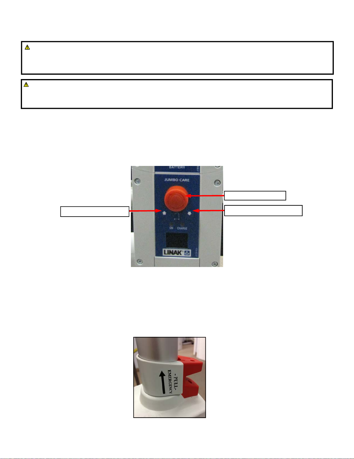
Emergency Stop:
Push the Emergency Stop button to cut all power on the Stand Aid. To resume power, release the
emergency stop button by turning clockwise as indicated by arrows on the Emergency Stop button.
Electrical emergency lowering/raising:
The Stand Aid boom is lowered or raised by pressing the UP and DOWN arrow button on the control box.
Mechanical emergency lowering:
In case of power failure, it is possible to mechanically lower a patient placed in SA-200 Stand Aid.
In order to lower the boom in an emergency situation, pull up the red lever located directly on the Stand
Aid’s actuator. The boom will lower as you press up and hold the lever. Release the red lever once you
have lowered the boom to a safe position.
Emergency Stop Button
Emergency Lowering Button
Emergency Raising Button
Page:18 Rev:04.2014 SA‐200‐Owner’sManual
Copyright Prism Medical UK 2014
Control Box: Usage information
The control box of SA-200 Stand Aid has an LCD display showing basic usage information on the display.
The following information will be visible on the LCD display of control box.
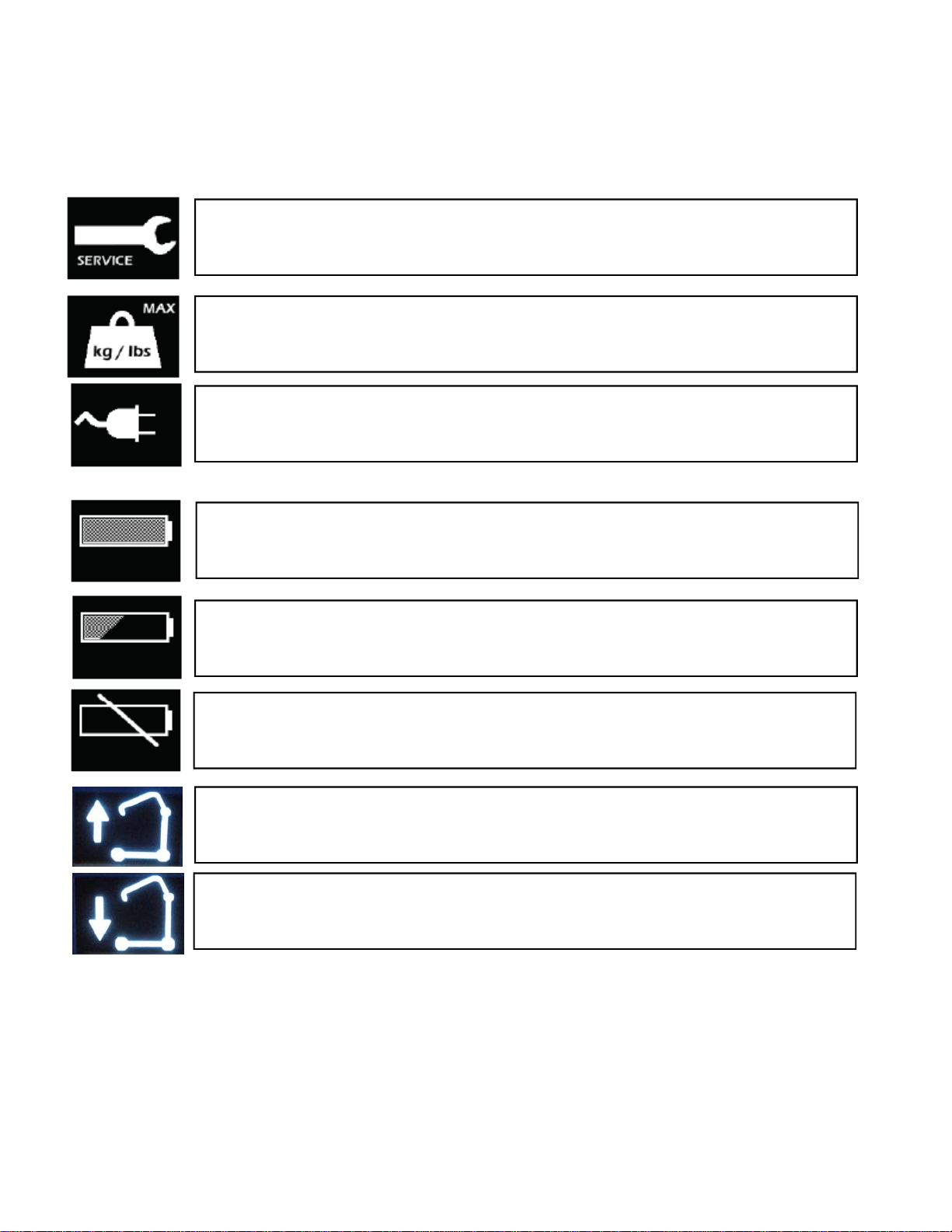
When it is time for service the service symbol will appear on the display will light up
and give notice to users about the need for service.
If the lift stops because of overload, the symbol will appear on the display and gives
the user the information about why the Stand Aid has stopped.
If someone tries to use the Stand Aid whilst plugged in, the symbol will appear on the
display. The user receives the information about why the Stand Aid is not working.
The use of the Stand Aid whilst charging is not possible.
The display showing a full battery symbol indicates that the battery is fully charged.
The display showing a half empty battery symbol indicates that it is time to charge the
battery.
The display showing a empty battery symbol indicates that the battery is completely
discharged.
The display showing a lifting actuator is moving up.
The display showing a lifting actuator is moving down.
SA‐200‐Owner’sManual Rev:04.2014Page:19
Copyright Prism Medical UK 2014
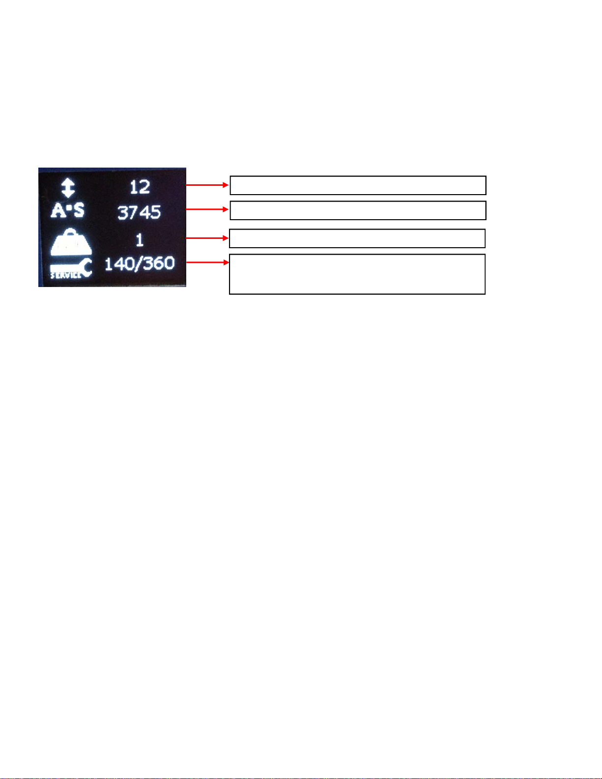
Control Box: Service information
The control box of SA-200 Stand Aid has an LCD display showing basic usage information on the display.
To get this information, press the “lifting arm up” button on hand control for half a second.
The information that appears on the display is as shown below.
Total cycles made by lifting actuator:
One cycle is defined as; Moving with load (the actuator draws more than 1.5 Amps).
Moving direction up for a minimum of 5 seconds (several activations are allowed), followed by moving
down for a minimum of 2 seconds.
Total work made by lifting actuator:
Work indicator for the lifting actuator measures via ampere usage x seconds in use.
The work indicator gives very good indication of how worn is the actuator. Typical minimum lifetime
performance without abuse of the actuator is 10000 cycles in life test equals to 5,600,000 A x S.
Total number of over loads:
Counts the number of times the lifting actuator has been overloaded.
Resetting of Service interval after service has been carried out:
Resetting of service is done by pressing 2 buttons; Lifting arm UP, and lifting arm DOWN on the hand
control at the same time for 5 seconds. After pressing the buttons for 5 seconds, you will receive an audio
signal indicating that the timer has been reset. The timer will clear the display for service symbol, and start
counting a new service period. This should only be done by an engineer or under guidance from a Prism
Medical UK representative.
Total cycles made by lifting actuator
Total work made by lifting actuator (A x S)
Total number of overloads
Number of days since last service / Number of days
between services
Page:20 Rev:04.2014 SA‐200‐Owner’sManual
Copyright Prism Medical UK 2014
Technical Specifications– Prism SA-200 Stand Aid
Table of contents
Other Prism Medical Mobility Aid manuals


Popular Mobility Aid manuals by other brands


Decon wheel
Decon wheel TNS Notos Assembly instructions

ExoAtlet
ExoAtlet ExoAtlet-II user manual

Invacare
Invacare Storm Series parts catalog

Rhythm Healthcare
Rhythm Healthcare B3800F manual

AMF-BRUNS
AMF-BRUNS PROTEKTOR installation manual

Drive DeVilbiss Healthcare
Drive DeVilbiss Healthcare OTTER Instructions for use