Prismafood 310 NEW User manual

INSTRUCTION MANUAL
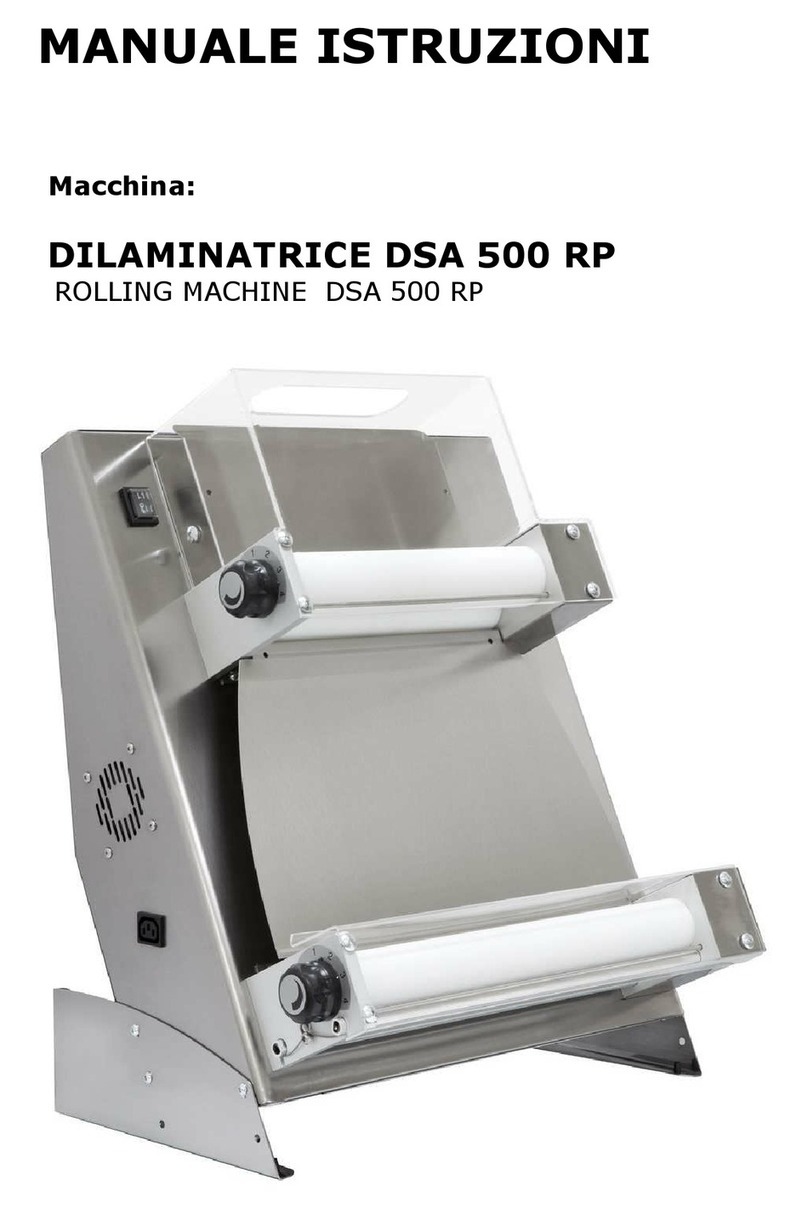
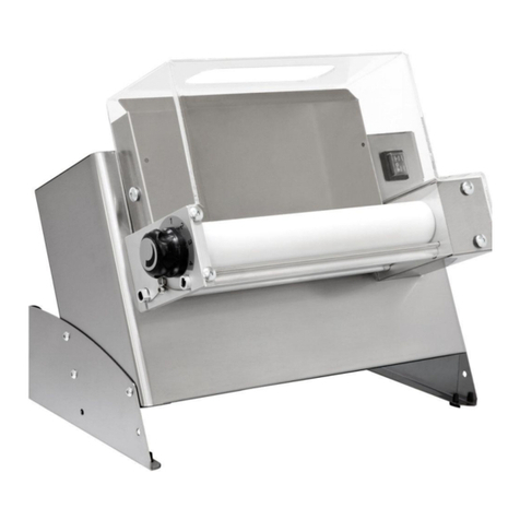
ROLLING MACHINE


EMISSION: 2014
The manufacturer is not under any obligation to notify of any future modifications of the product.
All rights of this document are reserved and no alteration or re-productions can be made without permission
of the manufacturer.
INTRODUCTION
This manual is specifically for the installation, use and maintenance of Rolling machines, so you are able to
use the product in the best way.
It is important that the manual is kept in good condition and should stay with the machine at all times,
including sale to another person, for security in the use of the machine.
The manual is divided in the following chapters:
CHAPTER 1:
General information.
CHAPTER 2:
Installation.
CHAPTER 3:
Functioning.
CHAPTER 4:
Usage.
CHAPTER 5:
Regulations.
CHAPTER 6:
Maintenance.
CHAPTER 7:
Demolition of the machine.
CHAPTER 8:
After sales service.

CHAPTER 1
GENERAL INFORMATION
1.1 WARRANTY
Guaranteed for one year from date of purchase. The date must be stamped on the guarantee on the day of
purchase.
Parts of the machine found to be a production defect except electrical components or parts worn out, will be
changed and serviced free by us in our company but only ex -works within this period.
Delivery expenses and costs of labor are excluded from the warranty.
The warranty will not be valid when the damage is due to: transportation, mistaken or insufficient
maintenance, unskilled operators, damaging, repairs made by un-authorized personnel, non-observance of
the instructions of the manual.
All reimbursements from the manufacturer are excluded for direct and indirect damages caused in the time
the machine is inactive for the following reasons: breakdown, waiting to be repaired, or anyway the non-
presence of the machine.
1.2 CHARACTERISTICS OF THE MACHINE
Rolling machines was made with the intention for food usage only to make dough for baking and for cakes,
to help make easier the creation of disk shapes for : pizza, bread, buns, cakes etc. maintaining the essential
characteristics of the mixture.
1.2.1.ROLLING MACHINES’MODELS 310 - 420 NEW e 310 - 420 TOUCH&GO NEW
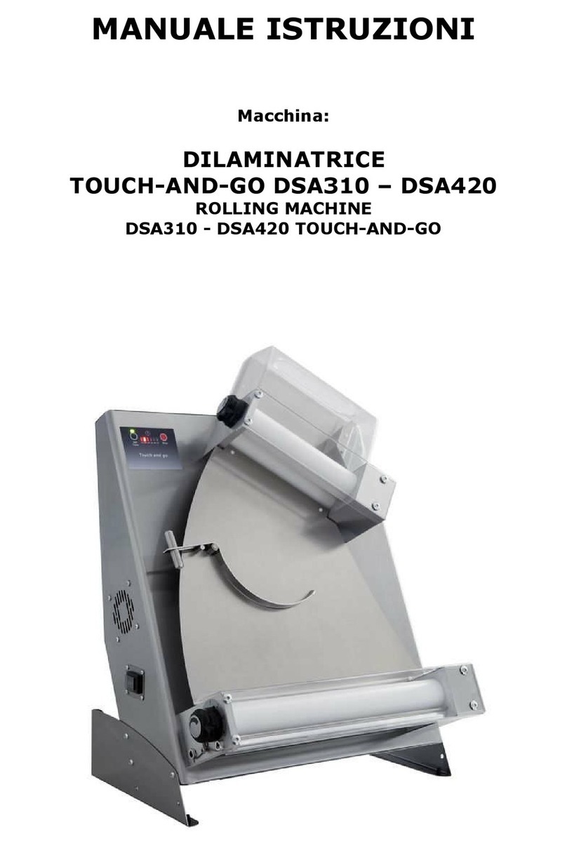
The models 310-420 & 310-420 TG are composed of: a steel structure, by two groups of rollers, with
relating guards, which are driven by belts, by an electric geared motor, controlled by a start switch fed
through cable with mains voltage, by a sling, two slides and an optional, that is the foot pedal start-stop
connected to the socket. The latter option is exclusive for the models 310-420, NOT touch & go.
1.2.2 ROLLING MACHINES’ MODELS 420 –500 RP
The models 420-500 RP are composed of: a metal structure, by two steel slides, two pairs of rollers with
relative guards, which are driven by belts, by an electric geared motor, controlled by a start switch, powered
through cable with mains voltage. supplemented by a foot control of start-stop connected to the socket.
1.2.3 ROLLING MACHINES’ MODELS 310/1 –500/1 –310/2
The models 310/1 - 500/1 –310/2 are composed of: a metal structure of steel, by a pair of rollers, with
relating guards, which are actuated by an electric gearmotor, controlled by a start switch fed through cable
with mains voltage, a slide and a pedal control start-stop connected to the socket. With the exception of the
model 310/2, the only composed of a pair of rollers to different diameters.

1.3 TECHNICAL CHARACTERISTICS
Descrizione
U.M.
310
NEW
310
T.GO
NEW
420
NEW
420
T.GO
NEW
420 RP
NEW
500 RP
NEW
310/1
500/1
310/2
Description
Dimensioni macchina
cm
47,5 x
37,5 x 66
58,5 x
43,5 x 79
58,5 x
43,5 x
71,5
66,5 x
43,5 x
71,5
48 x 33,5
x 43
65 x 34,5
x 43
65 x 34,5
x 43
Machine dimension
Peso netto
Kg
30
36
38
41
18
27
22
Net weight
Temperatura d’esercizio
°C
+15 ÷ +45
Operatine temperature
Peso pasta
gr
80 ÷ 210
210 ÷ 700
220 ÷
1000
220 ÷
1000
80 ÷ 210
210 ÷ 700
80 ÷ 210
Dough weight
Diametro pizza
cm
14 ÷ 29
26 ÷ 40
26 ÷ 40
26 ÷ 45
14 ÷ 29
26 ÷ 40
14 ÷ 29
Pizza diameter
Tensione d’alimentazione
Vac
230 ( 1 Ph + N + T ) 50 Hz
Alimentation tension
Potenza assorbita
W
250
Absorbed power
Potenza motore
W
240
Motor power

1.4 ELECTRICAL SCHEME ABOUT MODELS: 310-420 NEW; 420-500 RP; 310/1; 500/1; 310/2
M
E
N
I
O
II
ALIM. 230 VAC
MOTORE
MOTOR
INTERRUTTORE
SWITCH
CONN. FEMMINA
FEMALE PLUG
CONN. MASCHIO
MALE PLUG
PEDALE
TREADLE

sdsdsd
COMANDO SENSORE
1.4.1 ELECTRICAL SCHEME ABOUT MODELS: 310-420 TG NEW

1.5 INFORMATION REGARDING ACOUSTIC NOISES
The acoustic pressure level well-pondered A measured on an equal machine, turned out to be steady and
lower than 70 dB (A).
1.6 GENERAL SECURITY INDICATIONS
Although the machine is built in conformity to the required security rules regarding electrical, mechanical
and hygienic regulations it can be dangerous if:
- used in cases and conditions different to those described by the manufacturer.
- Modifications of the proportionate covers.
- Inattention to the instructions of:
Installation - functioning - usage - Maintenance.
IMPORTANT
Installation and maintenance must be done by qualified personnel authorized by the
manufacturer who is not responsible for any mistaken installation or manumission.
1.7 SECURITY INDICATIONS
IMPORTANT Carefully read the instructions before using the machine.
WARNING
To avoid dangerous conditions and/or possible injuries caused by: electric current, mechanical
parts, fire or hygiene problems, you must follow the safety warnings step by step.
A. KEEP IN ORDER YOUR WORKING AREA. Disorder can cause dangerous accidents.
B. CONSIDER ENVIRONMENTAL CONDITIONS. Do not use the machine in humid, wet or badly lit
environments, close to inflammable liquids or gas.
C. KEEP AWAY FROM CHILDREN AND NON AUTHORISED PERSONNEL. Do not permit them to go near the
machine or the working area.
D. ONLY UTILISE THE MACHINE WITH THE CORRECT VOLTAGE. Normal usage gives better results.
E. DRESS IN ADEQUATE WAY. Do not wear hanging clothes or any items which can be caught in the
machine. Use non-slip shoes. For hygiene and safety keep your hair tied back and wear protective gloves.
F. PROTECT THE CABLE. Do not pull the cable to extract the plug. Do not leave the cable near high
temperatures, sharp object, water or solvents.
G. AVOID INSECURE POSITIONS. Find the best surface to ensure the machine is balanced.
H. ALWAYS PAY MAXIMUM ATTENTION. Do not be distracted when using the machine.
I. TAKE THE PLUG OUT. When the machine is not in use, before cleaning, maintenance and moving it.
J. DO NOT USE FURTHER EXTENSIONS.
K. CHECK THAT THE MACHINE IS NOT DAMAGED. Before using the machine, carefully check that all security
devices are working. Check that: the mobile parts are not blocked, there are not any parts damaged, all
the parts have been set-up correctly and all the conditions that could influence the regular functioning of
the machine, are in working order.
L. REPAIRING THE MACHINE BY QUALIFIED PERSONNEL. The repairs can only be done by qualified people,
using original spare parts. The non-compliance with these rules can represent danger for the user.

CHAPTER 2
INSTALLATION
2.1 INSTRUCTIONS FOR THE USER
The environmental conditions in which the machine must be installed must follow these characteristics:
- be dry
- water and heat sources at safe distance
- adequate ventilation and lighting (corresponding to hygiene and security rules following the existing laws).
The surface must be horizontal, for normal ventilation of the machine no objects should obstruct.
IMPORTANT
The electric net must be provided with an auto-matic differential switch and this has to be
suitable to the machine and have a distance between the contacts of at least 3 mm. It is
particularly important to have a good ground system.
Verify that the electrical set-up corresponds with the numbers of the technical characteristics (1.3) and
on the small plate at the back of the machine.
2.2 INSTALLATION METHODS
The machine is supplied in a closed package.
After taking out the two covers, the higher slide and the machine proceed as follows:
- Position the machine in the corresponding location.
- Remove protection, avoid contact with utensils that can damage the surfaces.
NOTE
All the material belonging to the packaging, must be disposed in conformity of the law.
2.3 ELECTRICAL CONNECTION
The connection of the machine to the electrical network is made through a cable provided with a plug.
2.4 POSITIONING OF THE MACHINE
The plug must be accessible, does not have to require any kind of movement.
The cable from the machine to the wall plug must not be pulled tightly, also do not rest the machine on the
cable.

CHAPTER 3
FUNCTIONING
3.1 CONTROL DEVICES
The machine is provided with the following control devices:
SWITCH 1-0-2:
Position 1 –START
Position 0 –STOP
Position 2 –THE FOOT FUNCTION
on the front panel for 310 –420 TG:
- Black switch Set time (setting the working time);
- Red switch stoppage;
- Green light Machine starts.
3.2 FUNCTIONAL VERIFICATION
After you have inserted the line cord into the socket, the machine is ready for the functional verification.
START: press the button ( 1 ), the machine will start.
STOP: press the button ( 0 ), the machine will stop.
EXCEPT FOR MODELS 420/500 RP
START TO PEDAL:
Pressing the switch in position 2, the machine does not start, but waits. Applying light pressure to the foot
control, the rollers start spinning and the machine is ready for use.
STOP TO PEDAL:
Lifting his foot from the foot pedal the machine stops.
Finally, START THE MACHINE WITHOUT USING IT, LET IT RUN FOR 1 MINUTE AND MAKE SURE IT
IS FUNCTIONING PERFECTLY.

CHAPTER 4
USAGE
Before every work-cycle always make sure the machine is perfectly clean, in particular those surfaces that
get in touch with the dough. If necessary clean the machine following point:
4.1 USAGE OF THE MACHINE
4.1.1 MODELS 310 - 420 NEW
TO START: Press the button ( 1 ); the machine starts the two rollers and it is now ready to be used.
Before you introduce in the opening of the highest cover the small ball of dough made with flour and left to
rise (at least from 6 to 8 hours) squash the sides slightly so it can easily go through the highest rollers.
When the dough comes out you will see a reduction of thickness, with an oval shape, then sliding along the
scale it will make a turn of about 90° ready to go under the lowest rollers out of which it will have a disk
shape. This shape is not perfect so it needs the finishing touches by hand.
TO STOP: Press the button ( 0 ).
USAGE OF THE FOOT PEDAL
The foot pedal will only be installed by request of customer.
The foot pedal is a convenient alternative to the start and stop button and it makes possible to keep the
machine on during the time needed.
This device is connected to the machine by introducing the plug on the side of the machine.
TO START: Pressing the button ( 2 ), the machine doesn't start but it is on hold. Pressing slowly the foot
pedal, rollers start moving and the machine is ready for use
TO STOP: Taking your foot of the foot pedal the machine will stop working.
4.1.2 MODELS 310 - 420 TOUCH & GO NEW
TO START Press the switch at the side in position 1
Press the black switch of the unit “SET TIME” to set the working time from 10 to 35 seconds; the machine is
ready for the operational phase.
Before you introduce in the opening of the highest cover the small ball of dough made with flour and left to
rise (at least from 6 to 8 hours) squash the sides slightly so it can easily go through the highest rollers .The
rollers are automatically started with the contact of the dough with the top slide.
When the dough comes out you will see a reduction of thickness, with an oval shape, then sliding along the
scale it will make a turn of about 90° ready to go under the lowest rollers out of which it will have a disk
shape. This shape is not perfect so it needs the finishing touches by hand. The rollers turn will end
automatically at the end of the time previously set.
TO STOP: Press the switch at the side in position 0

4.1.3 models 420 - 500 RP
FUNCTIONS AND USAGE OF THE FOOT PEDAL. The foot control device controls the rollers to move
depending on desired speed and keeping the machine on during the time needed.
This device is connected to the machine by plugging the foot pedal into the main machine.
USAGE FOR THE SHAPING OF THE DISKS. After turning on the machine with the toggle switch in position
1 or 2, and starting the movement of rollers with the foot pedal, you can start working.
Before introducing in opening of the highest cover the small ball of dough previously left to rise (at least 6 to
8 hours), squash the sides slightly so it can easily go through the highest rollers When the dough comes out,
you will see a reduction of thickness , with an oval sAt the end of the trial, support on exit the dough with
your hand letting it advance slowly till it comes out, at the end of this the rollers must be stopped. Turn the
dough to 90° placing it in the lowest rollers ready for the next trial. Out of these rollers it will have a disk
shape, this shape is not perfect so it needs the finishing touches by hand.
USAGE FOR THE SHAPING OF RECTANGLES. Position a baking pan under the machine clean and big
enough to fit underneath.
Turn on the machine ,start rollers, then introduce in the opening of the highest cover the small ball of dough
previously left to rise (at least 6 to 8 hours), squash sides slightly to facilitate entrance in the rollers through
which , on the first trial the dough becomes thinner.
At the end of trial, it is necessary for medium or big weights to proceed as follows: go forward step by step ,
for another constant manual widening of the dough , positioning for the next trial trough the rollers , from
here the shaped dough will fall down into the baking pan.
IMPORTANT TURN OFF THE MACHINE WHEN YOU HAVE FINISCHED WORKING.
HOW TO REGULATE THE THICKNESS. Regulating the machine can only be recommended as there are
different characteristics of: the dough, the weight, the thickness, the size and the shape of the disk.
Therefore the correct regulating of the machine must be made by experimenting.
The machine is provided with a medium size regulation for the shapes of pizza.
IMPORTANT ALL REGULATION MUST BE MADE WHEN MACHINE IS ON HOLD.
With this machine you can have different thickness’ of dough to suit all requirements, just by turning and
turning the knob. Pull the black knob in order to release the levers.
To obtain the best results, we recommend to change the regulations.
The thickness can be modified turning the knob:
-MINIMUM THICKNESS (0) turning counter-clockwise
-MAXIMUM THICKNESS (4) turning clockwise.
NOTE TO AVOID THE DOUGH BRAKING, IT MUST PASS THROUGH THE ROLLERS ONLY ONCE.

4.1.4 models 310/1 –310/2 –500/1
TO START Push the button in position1; the machine starts the two rollers and it ‘s now ready to be used.
Before introducing the dough previously left to rise (at least 6 to 8 hours) open the rollers using the
handle(in position 3-4).The dough needs to be floured and squashed slightly to get through the rollers.when
the dough comes out,it will be in an oval shape and you will notice reduction of thickness. Towards the end
of this step,you need to support with your hand the dough until it come out completely. At this stage rotate
the dough in a transversal way of about 90° and put it trough the rollers once more (in position 1-2). You
will finally get an almost perfect disk shape dough that can be easily enhanced with few finishing touches by
hand.
TO STOP Press the button 0.
USAGE OF THE FOOT PEDAL. The foot pedal will only be installed by request of customer.
The foot pedal is a convenient alternative to the start and stop button and it makes possible to keep the
machine on during the time needed.
This device is connected to the machine by introducing the plug on the side if the machine.
TO START Pressing the button (2), the machine doesn't start but it is on hold. Pressing slowly the foot
pedal, rollers start moving and the machine is ready for use.
TO STOP Taking your foot of the foot pedal the machine will stop working.

CHAPTER 5
REGULATIONS
Regulating the machine can only be recommended as there are different characteristics of: the dough, the
weight, the thickness, the size and the shape of the disk.
Therefore the correct regulating of the machine must be made by experimenting.
The machine is provided with medium size regulation.
5.1 HOW TO REGULATE THE THICKNESS
IMPORTANT: ALL THE REGULATIONS HAVE TO BE DONE WHEN THE MACHINE IS OFF.
With this machine you can have different thickness’ of dough to suit all requirements, just by turning Knob
you can unblocked them pulling the black lever.
The thickness can be modified turning the knob:
-MINIMUM THICKNESS (0) turning counter-clockwise
-MAXIMUM THICKNESS (4) turning clockwise.
To obtain the best results we suggest you variegate the different regulations.
Ex.: Superior roller 3,5 mm
Lower roller 2 mm
NOTE: TO AVOID BREAKING THE DOUGH, LET IT PASS ONLY ONCE THROUGH THE ROLLERS.
5.2 HOW TO REGULATE THE SHAPE FOR ROLLLING MACHINES 310/420 E TOUCH&GO
To obtain the right shape of the disk , it is necessary to readjust the scale to the alteration of the weight of
the dough, to modify the position of the vertical perfectly to horizontal before entering the lowest rollers.
NOTE: MAKE SURE THAT THE SCALE IS IN THE HIGHEST POSITION WHEN NOT IN USE.
5.2.2 HOW TO REGULATE THE SMALL SCALE
This regulation gives the possibility to alter the rotation speed of the dough. Unscrewing the blocking screw
it is possible to modify the position of the counterbalance and its sensibility depending on its positioning in
one of the three holes in the small balance.
MAXIMUM BALANCE:
- position the counter-balance in the inside hole;
- this is recommended for lower weights.
MEDIUM BALANCE:
- position the counter-balance in the middle hole;
- this is recommended for medium weights.

MINIMUM BALANCE:
- position the counter-balance in the extreme hole;
- this is recommended for higher weights.
At the end of the regulation block the counterbalance screwing the screw.
CHAPTER 6
MAINTENANCE
WARNING
BEFORE DOING ANY KIND OF MAINTENANCE OR CLEANING YOU MUST TAKE OUT THE PLUG.
IN ANY CASE OF MALFUNCTIONING OR DAMAGES OF THE MACHINE YOU MUST APPLY FOR AUTHORISED
ASSISTANCE FROM THE MANUFACTURER. (SEE CHAPTER 8).
6.1 CLEANING
Cleaning must be done every time the machine has been used following all the rules to prevent
malfunctioning of the machine and for hygienic purposes.
Using a proper brush, first clean the residue of flour and dough.
Release the springs, loosen the dough scrapers then turn the regulating levers in position, maximum
opening of the rollers.
Clean very carefully the machine and all the parts, also the disassembled parts, using a sponge or a cloth
dampen with tepid water and detergent. Rinse out very well so to remove completely the detergent. Dry
with blotting paper, then clean first the surface in contact with the dough and then all the machine with a
clean and soft cloth soaked with a specific disinfectant for alimentary machines.
WARNING
IT IS IMPORTANT NOT TO USE CHEMICAL ABRASIVE OR CORROSIVE PRODUCTS. ABSOLUTELY AVOID TO
USE RUNNING WATER, NON-SMOOTH TOOLS SUCH AS STEEL WOOL, SPONGES ETC… THESE CAN DAMAGE
THE SURFACE AND COMPROMISE THE HYGIENICALLY SAFETY.
Mount everything in this order: the scrapingdough pieces, the springs, the slides and the protections.
VERIFY THAT ALL PIECES HAVE BEEN CORRECTLY POSITIONED AND FIXED.
6.2 LUBRICATION OF SHAFTS AND ROLLERS
It is necessary to grease shafts and rollers every year. Take off the protections, the slanted wall, the springs
and the doughscrapers; unscrew the fixing screws and take off first the back-panel and then the stands
and ; Take off the rollers and the joints . Clean all these parts accurately by means of a sponge, warm
water and food detergent, rinse thoroughly and dry it with absorbing paper. Grease both the shafts and the
Back on and fix all the parts, starting from the last taken-off piece.

6.3 POSSIBLES ANOMALIES
ANOMALY
CAUSE
SOLUTION
The machine does’t start
1_ Electrical power is missing
2_ The foot - control is on.
1_ Check the general contactor, the
plug and the feeding cable.
2_ Push the foot pedal
CHAPTER 7
DEMOLITION OF THE MACHINE
In cases of dismantling and/or demolition of the machine, the pieces which the machine is made of, do not
present any kind of danger that necessitates any particular caution.
To facilitate the recycling process of the materials, you must separate all electrical and thermo-plastic
components.
CHAPTER 8
AFTER-SALE SERVICE
8.1 SPARE PARTS
For a demand of spare parts:
EEC Countries: Contact exclusively place of purchase

8.1.2 SPARE PARTS FOR ROLLING MACHINES
310 NEW ROLLING MACHINE
420 NEW ROLLING MACHINE
POS.
ART.
DESCRIPTION
ART.
DESCRIPTION
1
5T100001
PLUG STRAP
5T100001
PLUG STRAP
2
5S500001
SEEGER Ø10 UNI 7435
5S500001
SEEGER Ø10 UNI 7435
3
3P020001
KNOB CONTROL
3P020001
KNOB CONTROL
5
5S510005
CILINDRIC SHEET 3X14
5S510005
CILINDRIC SHEET 3X14
6
3S010032
LOWER ROLLERS SUPPORT
3S010032
LOWER ROLLERS SUPPORT
7
3S010027
UPPER ROLLERS SUPPORT
3S010027
UPPER ROLLERS SUPPORT
9
3A010042
LOWER CILINDRIC SHAFT 310
3A010047
LOWER CILINDRIC SHAFT 310
10
3A010032
UPPER CILINDRIC SHAFT 310
3A010037
UPPER CILINDRIC SHAFT 310
11
3R020005
BACK DOUGH SCRAPER 310
3R020010
BACK DOUGH SCRAPER 310
12
3R010010
LOWER CILINDRIC ROLLER 310
3R010020
LOWER CILINDRIC ROLLER 310
13
3R010001
UPPER CILINDRIC ROLLER 310
3R010005
UPPER CILINDRIC ROLLER 310
17
5A010001
ELASTIC RING
5A010001
ELASTIC RING
18
3A010072
LOWER MOTOR SHAFT
3A010072
LOWER MOTOR SHAFT
19
3A010071
UPPER MOTOR SHAFT
3A010071
UPPER MOTOR SHAFT
20
5C030000
KBC 6202 ZZ BEARING
5C030000
KBC 6202 ZZ BEARING
21
5L500017
UNI 6604-A 5X5X14 KEY
5L500017
UNI 6604-A 5X5X14 KEY
22
5I200005
DRIVING GEAR
5I200005
DRIVING GEAR
25
3S010007
LOWER GEARS SUPPORT
3S010007
LOWER GEARS SUPPORT
26
3S010003
UPPER GEARS SUPPORT
3S010003
UPPER GEARS SUPPORT
27
5C030007
16002 2Z BEARING
5C030007
16002 2Z BEARING
28
5S500010
SEEGER Ø15 UNI 7435
5S500010
SEEGER Ø15 UNI 7435
31
5G010005
MALE COUPLING
5G010005
MALE COUPLING
32
5G010001
FEMALE COUPLING
5G010001
FEMALE COUPLING
33
3R010050
LOWER ECCENTRIC ROLLER 310
3R010060
LOWER ECCENTRIC ROLLER 310
34
3R010040
UPPER ECCENTRIC ROLLER 310
3R010045
UPPER ECCENTRIC ROLLER 310
35
3R020025
FRONT DOUGH SCRAPER 310
3R020030
FRONT DOUGH SCRAPER 310
36
3T050035
LOWER STAY ROD 310
3T050025
LOWER STAY ROD 310
37
3T050040
UPPER STAY ROD 310
3T050030
UPPER STAY ROD 310
38
3A010011
LOWER ECCENTRIC SHAFT 310
3A010016
LOWER ECCENTRIC SHAFT 310
39
3A010002
UPPER ECCENTRIC SHAFT 310
3A010006
UPPER ECCENTRIC SHAFT 310
41
5M500005
DOUGH SCRAPER SPRING
5M500005
DOUGH SCRAPER SPRING
42
5L500010
UNI 6604-A 4X4X15 KEY
5L500010
UNI 6604-A 4X4X15 KEY
43
5M500001
KNOB REGULATION SPRING
5M500001
KNOB REGULATION SPRING
45
4C010016
BACK COVER 310 NEW
4C010008
BACK COVER 310 NEW
46
5R010001
NMRV30 REDUCER
5R010001
NMRV30 REDUCER
47
5C020010
310 ROLL MACHINE BELT
5C020015
310 ROLL MACHINE BELT
48
4P010007
310 NEW PLATE
4P010012
310 NEW PLATE
50
4T010106
310 NEW CHASSIS
4T010111
310 NEW CHASSIS
51
3D010005
UPPER SLIDE SPACER
3D010005
UPPER SLIDE SPACER
53
4S010003
310 UPPER SLIDE
4S010006
310 UPPER SLIDE
54
4D010001
DEFLECTOR
4D010001
DEFLECTOR

55
4S010071
310 NEW LOWER SLIDE
4S010074
310 NEW LOWER SLIDE
56
4B010001
ROCKING 310
4B010005
ROCKING 310
57
5L500031
UNI6604-A 5X5X25 KEY
5L500031
UNI6604-A 5X5X25 KEY
58
7G010066
310 NEW UPPER ROLLER GROUP
7G010070
310 NEW UPPER ROLLER GROUP
59
4C010070
PROTECTION GEAR SUPPORT
4C010070
PROTECTION GEAR SUPPORT
60
4P020026
310 UPPER PROTECTION
4P020031
310 UPPER PROTECTION
61
4P020006
310 LOWER PROTECTION
4P020015
310 LOWER PROTECTION
62
4C010070
PROTECTION GEAR SUPPORT
4C010070
PROTECTION GEAR SUPPORT
63
7G010068
310 NEW LOWER ROLLER GROUP
7G010072
310 NEW LOWER ROLLER GROUP
64
5L500020
UNI 6604-A 5X5X20 KEY
5L500020
UNI 6604-A 5X5X20 KEY
65
5L500024
UNI 6604-A 5X5X60 KEY
5L500024
UNI 6604-A 5X5X60 KEY
66
3C010001
COUNTERBALANCE ROCKING
3C010001
COUNTERBALANCE ROCKING
67
4P030016
DX FOOT 310 NEW
4P030021
DX FOOT 310 NEW
68
3P030001
PIN ROCKING INOX D.8
3P030001
PIN ROCKING INOX D.8
70
5I100001
SWITCH
5I100001
SWITCH
72
4P030017
SX FOOT 310 NEW
4P030022
SX FOOT 310 NEW
73
5P020001
PEDAL
5P020001
PEDAL
74
5P200001
PEDAL POWER
5P200001
PEDAL POWER
75
5V050005
230V FAN
5V050005
230V FAN
78
3T300010
ROLL MACHINE HOLDING BELT
3T300010
ROLL MACHINE HOLDING BELT
79
3P010010
ROLL MACHINE PULLEY
3P010010
ROLL MACHINE PULLEY
80
5P100015
Ø 6-10,5 CABLE PRESS
5P100015
Ø 6-10,5 CABLE PRESS
81
5M020010
ROLL MACHINE MOTOR 0,25KW 230V
5M020010
ROLL MACHINE MOTOR 0,25KW 230V
7I010002
COMPLETE ECCENTRIC DUCT GEAR
7I010002
COMPLETE ECCENTRIC DUCT GEAR
30
3I010002
ECCENTRIC GEAR HUB
3I010002
ECCENTRIC GEAR HUB
16
5I200006
STEEL DUCT GEAR
5I200006
STEEL DUCT GEAR
15
5B100010
BUSH
5B100010
BUSH
29
(2x)
5L500015
UNI 6604-A 5X5X10 KEY
5L500015
UNI 6604-A 5X5X10 KEY
7I010001
COMPLETE CYLINDRICAL DUCT GEAR
7I010001
COMPLETE CYLINDRICAL DUCT GEAR
14
3I010006
CYLINDRICAL GEAR HUB
3I010006
CYLINDRICAL GEAR HUB
16
5I200006
STEEL DUCT GEAR
5I200006
STEEL DUCT GEAR
15
5B100010
BUSH
5B100010
BUSH
29
(2x)
5L500015
UNI 6604-A 5X5X10 KEY
5L500015
UNI 6604-A 5X5X10 KEY
* EXPLODED REFERENCE TO SPARE PARTS ABOUT THE ROLLER GROUP, AT THE END MANUAL.
.


310 T&G NEW ROLLING MACHINE
420 T&G NEW ROLLING MACHINE
POS.
ART.
DESCRIPTION
ART.
DESCRIPTION
1
5T100001
PLUG STRAP
5T100001
PLUG STRAP
2
5S500001
SEEGER Ø10 UNI 7435
5S500001
SEEGER Ø10 UNI 7435
3
3P020001
KNOB CONTROL
3P020001
KNOB CONTROL
5
5S510005
CILINDRIC SHEET 3X14
5S510005
CILINDRIC SHEET 3X14
6
3S010032
LOWER ROLLERS SUPPORT
3S010032
LOWER ROLLERS SUPPORT
7
3S010027
UPPER ROLLERS SUPPORT
3S010027
UPPER ROLLERS SUPPORT
9
3A010042
LOWER CILINDRIC SHAFT 310
3A010047
LOWER CILINDRIC SHAFT 310
10
3A010032
UPPER CILINDRIC SHAFT 310
3A010037
UPPER CILINDRIC SHAFT 310
11
3R020005
BACK DOUGH SCRAPER 310
3R020010
BACK DOUGH SCRAPER 310
12
3R010010
LOWER CILINDRIC ROLLER 310
3R010020
LOWER CILINDRIC ROLLER 310
13
3R010001
UPPER CILINDRIC ROLLER 310
3R010005
UPPER CILINDRIC ROLLER 310
17
5A010001
ELASTIC RING
5A010001
ELASTIC RING
18
3A010072
LOWER MOTOR SHAFT
3A010072
LOWER MOTOR SHAFT
19
3A010071
UPPER MOTOR SHAFT
3A010071
UPPER MOTOR SHAFT
20
5C030000
KBC 6202 ZZ BEARING
5C030000
KBC 6202 ZZ BEARING
21
5L500017
UNI 6604-A 5X5X14 KEY
5L500017
UNI 6604-A 5X5X14 KEY
22
5I200005
DRIVING GEAR
5I200005
DRIVING GEAR
25
3S010007
LOWER GEARS SUPPORT
3S010007
LOWER GEARS SUPPORT
26
3S010003
UPPER GEARS SUPPORT
3S010003
UPPER GEARS SUPPORT
27
5C030007
16002 2Z BEARING
5C030007
16002 2Z BEARING
28
5S500010
SEEGER Ø15 UNI 7435
5S500010
SEEGER Ø15 UNI 7435
31
5G010005
MALE COUPLING
5G010005
MALE COUPLING
32
5G010001
FEMALE COUPLING
5G010001
FEMALE COUPLING
33
3R010050
LOWER ECCENTRIC ROLLER 310
3R010060
LOWER ECCENTRIC ROLLER 310
34
3R010040
UPPER ECCENTRIC ROLLER 310
3R010045
UPPER ECCENTRIC ROLLER 310
35
3R020025
FRONT DOUGH SCRAPER 310
3R020030
FRONT DOUGH SCRAPER 310
36
3T050035
LOWER STAY ROD 310
3T050025
LOWER STAY ROD 310
37
3T050040
UPPER STAY ROD 310
3T050030
UPPER STAY ROD 310
38
3A010011
LOWER ECCENTRIC SHAFT 310
3A010016
LOWER ECCENTRIC SHAFT 310
39
3A010002
UPPER ECCENTRIC SHAFT 310
3A010006
UPPER ECCENTRIC SHAFT 310
41
5M500005
DOUGH SCRAPER SPRING
5M500005
DOUGH SCRAPER SPRING
42
5L500010
UNI 6604-A 4X4X15 KEY
5L500010
UNI 6604-A 4X4X15 KEY
43
5M500001
KNOB REGULATION SPRING
5M500001
KNOB REGULATION SPRING
45
4C010016
BACK COVER 310 NEW
4C010008
BACK COVER 310 NEW
46
5R010001
NMRV30 REDUCER
5R010001
NMRV30 REDUCER
47
5C020010
310 ROLL MACHINE BELT
5C020015
310 ROLL MACHINE BELT
48
4P010007
310 NEW PLATE
4P010012
310 NEW PLATE
50
4T010108
310 T&G NEW CHASSIS
4T010113
310 T&G NEW CHASSIS
51
3D010005
UPPER SLIDE SPACER
3D010005
UPPER SLIDE SPACER
52
5S010070
CAPACITIVE SENSOR T&G ROLLING
MACHINES
5S010070
CAPACITIVE SENSOR T&G ROLLING MACHINES
53
4S010002
310 T&G UPPER SLIDE
4S010007
310 T&G UPPER SLIDE
54
4D010001
DEFLECTOR
4D010001
DEFLECTOR
This manual suits for next models
8
Table of contents
Other Prismafood Commercial Food Equipment manuals
Popular Commercial Food Equipment manuals by other brands

Costan
Costan SAMBA User instructions

Firex
Firex CUCIMAX CBTG180A user manual

Metos
Metos 051R Installation, Utilization and Maintenance Manual

Anets
Anets PASTA PRO GPC-14 INSTALLATION & USER OPERATION MANUAL

croydon
croydon MPED Series instruction manual

Structural Concepts
Structural Concepts BLEND NM4855DSSV user manual

CARTER-HOFFMANN
CARTER-HOFFMANN HL5 Series Owner's/operator's manual

Giorik
Giorik HI LITE Installation, Operation and Maintenace Manual

CIAM
CIAM BRILLIANT Series user manual

BRIKA
BRIKA BSP-18 product manual

Cuppone
Cuppone Michelangelo ML 435/1 User and installation manual

mixologiq
mixologiq MIXO TWO user guide