Priva Compass User manual

Manual
>INSTALLING PRIVA COMPASS

Contact
Priva (head office)
Zijlweg 3
2678 LC De Lier
The Netherlands
See www.priva.com for contact information of a Priva office or partner for your region.
5001018Article number:
00.014Version:
August 2019Date:
© Copyright Priva B.V. All rights reserved.
No part of this publication may be reproduced, published or stored in a retrieval system without
written prior permission of Priva.
This publication has been developed with care. However, the products shown may differ in dimensions
and design from the actual products. Priva will not accept any responsibility for damages caused by
any errors or deficiencies in this publication. Priva may modify its products and the associated
manuals without prior notice. Priva advises to check product, installation, hardware and if present
software on irregularities.
Priva owns the patents, patent applications, trade marks or other intellectual property rights regarding
the products described in this publication. With this publication Priva does not grant the use of the
aforementioned intellectual property rights. Product and company names this publication may not
be used without the permission of Priva.
All Priva products and services are subject to the relevant Priva general terms and conditions. These
general terms and conditions can be read and downloaded at www.priva.com/general-conditions.

Contents
About this manual ............................................................................................ 6
Related documents .............................................................................................................................. 6
Target groups and required competencies ....................................................................................... 6
Safety ................................................................................................................. 8
Safety - general ..................................................................................................................................... 8
Electrical safety ..................................................................................................................................... 8
Warranty ............................................................................................................ 9
Functions and intended use ............................................................................ 9
Compass system overview ............................................................................ 10
Compass cabinet components ..................................................................... 11
Compass FG terminals ....................................................................................................................... 13
Overview of connecting sensors and systems ............................................ 14
Compass system installation steps .............................................................. 15
General installation ............................................................................................................................ 15
Installing field equipment ................................................................................................................. 15
Position the Compass cabinet .......................................................................................................... 15
Cable grommets and glands ............................................................................................................. 17
Connecting the mains cable .............................................................................................................. 17
Setting the mains voltage on the 24 VAC transformer .................................................................. 19
Connecting Ethernet cables .............................................................................................................. 19
Connecting WLAN .............................................................................................................................. 21
Using the alarm output ..................................................................................................................... 21
Switching the Compass system on and off ..................................................................................... 22
Commissioning Compass .................................................................................................................. 23
Updating Compass software ............................................................................................................ 27
IP address assignment ...................................................................................................................... 29
Maintenance, checking and calibration ........................................................................................... 30
Replacing fuses ................................................................................................................................... 30
Troubleshooting the Compass system ............................................................................................ 31
Performing a reset of the VDC power supply ................................................................................. 31
Priva Blue ID hardware .................................................................................. 32
Earth contact ....................................................................................................................................... 32
Switching system power on and off ................................................................................................. 32
Connecting field equipment ............................................................................................................. 33
1Installing Priva Compass - 00.014

Connections - RS485 .......................................................................................................................... 33
Connecting hardware ........................................................................................................................ 34
Disassembling hardware ................................................................................................................... 40
Maintaining hardware ....................................................................................................................... 42
Priva weather station WSC11 ........................................................................ 43
Principle ............................................................................................................................................... 43
Positioning the weather station ....................................................................................................... 44
WSC11 Connection ............................................................................................................................. 44
Mounting of WSC11 ........................................................................................................................... 47
Specifications ...................................................................................................................................... 48
Meteorological station .................................................................................. 52
Meteorological station ...................................................................................................................... 52
Positioning the meteorological station ............................................................................................ 52
Fitting the sensors .............................................................................................................................. 52
Ridge direction meteorological station ............................................................................................ 54
Mounting the mast ............................................................................................................................. 54
Maintenance of Meteorological station ........................................................................................... 56
Meteorological station specifications .............................................................................................. 56
Weather interface WI2 ................................................................................... 58
Connecting sensors to the Weather interface WI2 ........................................................................ 58
Connecting the Weather interface WI2 to a universal input ......................................................... 60
Extending cabling ............................................................................................................................... 60
Setting the Weather interface WI2 jumpers .................................................................................... 61
Specifications ...................................................................................................................................... 62
Linear light sensor LS2 and LS2WI ............................................................... 64
Linear light sensor .............................................................................................................................. 64
Mounting ............................................................................................................................................. 64
Connecting .......................................................................................................................................... 65
Maintain linear light sensor .............................................................................................................. 65
Specifications ...................................................................................................................................... 66
Radiation sensor CM3P .................................................................................. 67
Radiation sensor CM3P ..................................................................................................................... 67
Installation .......................................................................................................................................... 67
Connecting .......................................................................................................................................... 68
Solari CM3P maintenance ................................................................................................................. 68
Specifications ...................................................................................................................................... 69
Rain sensor RD2WI ......................................................................................... 70
Rain sensor ......................................................................................................................................... 70
Installing Priva Compass - 00.0142
Priva

Mounting ............................................................................................................................................. 70
Connecting .......................................................................................................................................... 71
Speeding up the initial rain detection .............................................................................................. 71
Rain sensor maintenance .................................................................................................................. 71
Specifications ...................................................................................................................................... 72
Wind direction sensor WDS2WI .................................................................... 73
Wind direction sensor ........................................................................................................................ 73
Mounting ............................................................................................................................................. 73
Connecting .......................................................................................................................................... 73
Maintenance of wind direction sensor ............................................................................................ 74
Specifications ...................................................................................................................................... 74
Wind speed sensor WSS2WI ......................................................................... 75
Wind speed sensor ............................................................................................................................ 75
Mounting ............................................................................................................................................. 75
Connecting .......................................................................................................................................... 76
Wind speed sensor maintenance ..................................................................................................... 76
Specifications ...................................................................................................................................... 77
Outside temperature sensor OTS2 ............................................................. 78
Outside temperature sensor ............................................................................................................ 78
Connecting .......................................................................................................................................... 78
Mounting ............................................................................................................................................. 79
Outside temperature sensor maintenance .................................................................................... 79
Specifications ...................................................................................................................................... 80
Flow sensor ..................................................................................................... 82
Connecting .......................................................................................................................................... 82
Cleaning the flow sensor ................................................................................................................... 83
Technical specifications – flow sensor ............................................................................................. 83
Technical specifications - T-piece for flow sensor .......................................................................... 83
pH interface ..................................................................................................... 85
Connecting the pH interface ............................................................................................................. 85
Calibrating the pH interface .............................................................................................................. 85
Technical specifications - pH-interface ............................................................................................ 85
Technical specifications – pH sensor ............................................................................................... 86
Dosing Channel Driver ................................................................................... 87
Operation of Dosing Channel Driver ............................................................................................... 87
Connecting the Dosing Channel Driver ........................................................................................... 88
Specifications Dosing Channel Driver .............................................................................................. 89
3Installing Priva Compass - 00.014

EC-DSS interface ............................................................................................. 91
Operation of EC-DSS interface .......................................................................................................... 91
Connecting the EC-DSS interface ..................................................................................................... 91
Expanding the EC-DSS interface ....................................................................................................... 92
Technical specifications - EC-DSS-interface ..................................................................................... 92
Connecting the Compass EC sensor ................................................................................................ 93
Specifications for EC sensor .............................................................................................................. 94
Calibrating the EC measurement (Compass) .................................................................................. 94
Drain water sensor ......................................................................................... 96
Use ....................................................................................................................................................... 96
Overview .............................................................................................................................................. 97
Mounting the Drain water sensor .................................................................................................... 97
Connecting the Drain water sensor (Compass) .............................................................................. 99
Specifications of the Drain water sensor 1 kΩ ............................................................................. 100
Groscale ......................................................................................................... 101
Layout ................................................................................................................................................ 102
Preparing for installation ................................................................................................................ 103
Installation ........................................................................................................................................ 104
Connecting Groscale to Compass .................................................................................................. 106
Commissioning ................................................................................................................................. 107
LEDs ................................................................................................................................................... 110
Operation and display ..................................................................................................................... 110
Explanation menus .......................................................................................................................... 112
Maintenance Groscale ..................................................................................................................... 116
Replacement and repair .................................................................................................................. 116
Troubleshooting ............................................................................................................................... 117
Technical specifications ................................................................................................................... 118
Disposing of waste products ...................................................................... 119
General Compass specifications ................................................................ 120
Electrical specifications ................................................................................................................... 120
Other specifications ......................................................................................................................... 121
WLAN specifications ........................................................................................................................ 121
Preconditions for installation and use .......................................................................................... 122
General specifications of Priva Blue ID C-Line controllers and
modules ......................................................................................................... 123
Specifications of Priva Blue ID C4 C-MX34 Controller ................................................................. 125
Specifications of Priva Blue ID C-Line MX34 Mix input/output module ................................... 128
Specifications of Priva Blue ID C-Line UI8 Universal input module .......................................... 129
Installing Priva Compass - 00.0144
Priva

Specifications of Priva Blue ID C-Line DOR6 Relay output module ........................................... 130
Specifications of inputs and outputs ............................................................................................. 131
LEDs and line-up LED ....................................................................................................................... 135
5Installing Priva Compass - 00.014
About this manual
This manual provides information on installing and maintaining the Compass system. The manual
specifically focuses on the field equipment in a Compass system.
This manual is intended only for installers and service engineers, not for users.
A Compass Operator manual is available for users. User documentation must be available
in the workplace.
The manual deals with the following topics:
• the components of Compass
• installing and connecting field equipment to the Compass cabinet
• specifications
• resolving errors
Related documents
AvailabilityArticle no.Document
included in the box of the Compass cabinet-insert sheet on connecting and suspending Compass
as Help in the Compass Operator-Compass Operator manual
download as a PDF via the Priva Support
Portal: https://support.priva.nl (registered
partners only)
-Compass price list
Priva Blue ID C-Line documentation
AvailabilityArticle no.Document
5001010Installing and commissioning Priva Blue ID C-Line manual • download as PDF via the Priva Support
Portal: https://support.priva.nl
(registered partners only)
5001011Communicating with Priva Blue ID C-Line manual
5001012Priva Blue ID C-Line connection examples • view in your browser via the Manuals
and other documentation link in the Top
Control installation menu
5001135datasheet Priva Blue ID C-Line system overview
5001013Priva Blue ID C-Line Quick Reference Card
variousdatasheets for the Priva Blue ID C-Line hardware
Target groups and required competencies
Training, knowledge and experience requiredTasks and responsibilitiesTarget group
the system:
installers / service
engineers • technical training in the field of electrical
engineering and process engineering• transport •• experience with electrical installations for
the horticulture industry
position
• install •• command of (technical) Englishcommission and set up
• test after initial commissioning and
resolve any problems
• operate
• perform an annual check
• take it out of operation and dispose of it
at end of service life
Explanation of symbols in this document
DANGER
Instruction to prevent physical injury or damage to the product, the installation or the
environment.
Installing Priva Compass - 00.0146
Priva

CAUTION
Instruction to prevent problems with the product or the service.
INFORMATION
Additional information.
TIP
A tip or other useful information.
7Installing Priva Compass - 00.014
About this manual

Safety
• Before starting to work with the product, read the entire manual so that you are familiar
will all safety instructions and safety precautions.
• In addition, read any other manuals supplied with specific components.
Safety - general
• Use the system only for its intended purpose.
• Follow the instructions in this manual and the related manuals.
• Making alterations to the safeguards and safety icons on the equipment is prohibited.
•Both the installer/service engineer and the user must regularly check and maintain the equipment
(the safeguards in particular) in accordance with the instructions in this manual. Keep the
equipment clean and the surroundings tidy.
• Report malfunctions or damage to your installer immediately. Take the equipment out of
operation and do not use it if a defect is found.
• Only use original spare parts for repairs (refer to the spare parts price list).
• After making repairs check the correct status and functioning of the equipment.
• If the user allows personnel to operate the equipment, he/she must adequately instruct this
personnel. In particular this should cover the safety risks and safety instructions stated in this
manual. He/she must also supervise correct compliance with the instructions.
• Display the safety icons that are applicable in the room where the equipment is set up.
• Position the cabinet in a space that meets the environmental requirements.
• Make sure the space and the cabinet are easily accessible. There must be enough space to open
the cabinet for maintenance and installation. This is especially important if you need to switch
off the system with the circuit breaker in the event of problems.
• Keep water out of the cabinet. Do not use a high pressure cleaner to clean the cabinet.
• Do not use aggressive cleaning agents, scouring sponges or abrasives for cleaning.
• Damage to Compass components may occur as a result of:
• Incorrect transportation or storage.
• Incorrect installation and assembly.
• Incorrect environmental conditions.
• Wearing, aging or metal fatigue.
Electrical safety
The unit is powered from the mains voltage. There is a potential hazard of electrocution or fire
resulting from a short circuit. You must therefore adhere to the following safety instructions:
• Keep the housings of electrical components closed.
• Keep the electrical parts dry.
• Make sure the earthing is connected according to the principle "make contact first, break contact
last". The earth wire must therefore be twice as long as the phase wire and neutral wire.
• Ensure that the unit is connected to its own fuse group with the correct fuses.
During installation, maintenance or while resolving faults it may be necessary to open the housing
for the electrical components. In this case, adhere to the following safety instructions:
• Preferably, make the unit totally free of electricity by removing the plug from the socket outlet,
switching off the circuit breaker or by removing fuses from the fuse group.
• If the unit cannot be made free of electricity then take extreme care. Use well-insulated tools
and do not touch the ends of wires, connections and electrical components with your bare
hands. Keep the surroundings dry and ensure that there is someone close by to keep an eye on
you.
• Wear an earthed wrist strap when working in the cabinet. Otherwise the electronic components
may be damaged due to static electricity.
Installing Priva Compass - 00.0148
Priva

Warranty
The warranty expires if the product is not installed, used and maintained in accordance with the
instructions in the Priva manual. For more details refer to the general terms of delivery (Priva will
supply these on request and refer to www.priva.com) and the specifically agreed terms of delivery.
Functions and intended use
The function of the Compass system is to control, regulate and monitor equipment in the horticulture
industry in order to maintain an optimum environment for the crop. Connected field equipment is
controlled from the Compass cabinet. The field equipment consists of various sensors and other
systems for the horticulture industry.
9Installing Priva Compass - 00.014
Warranty
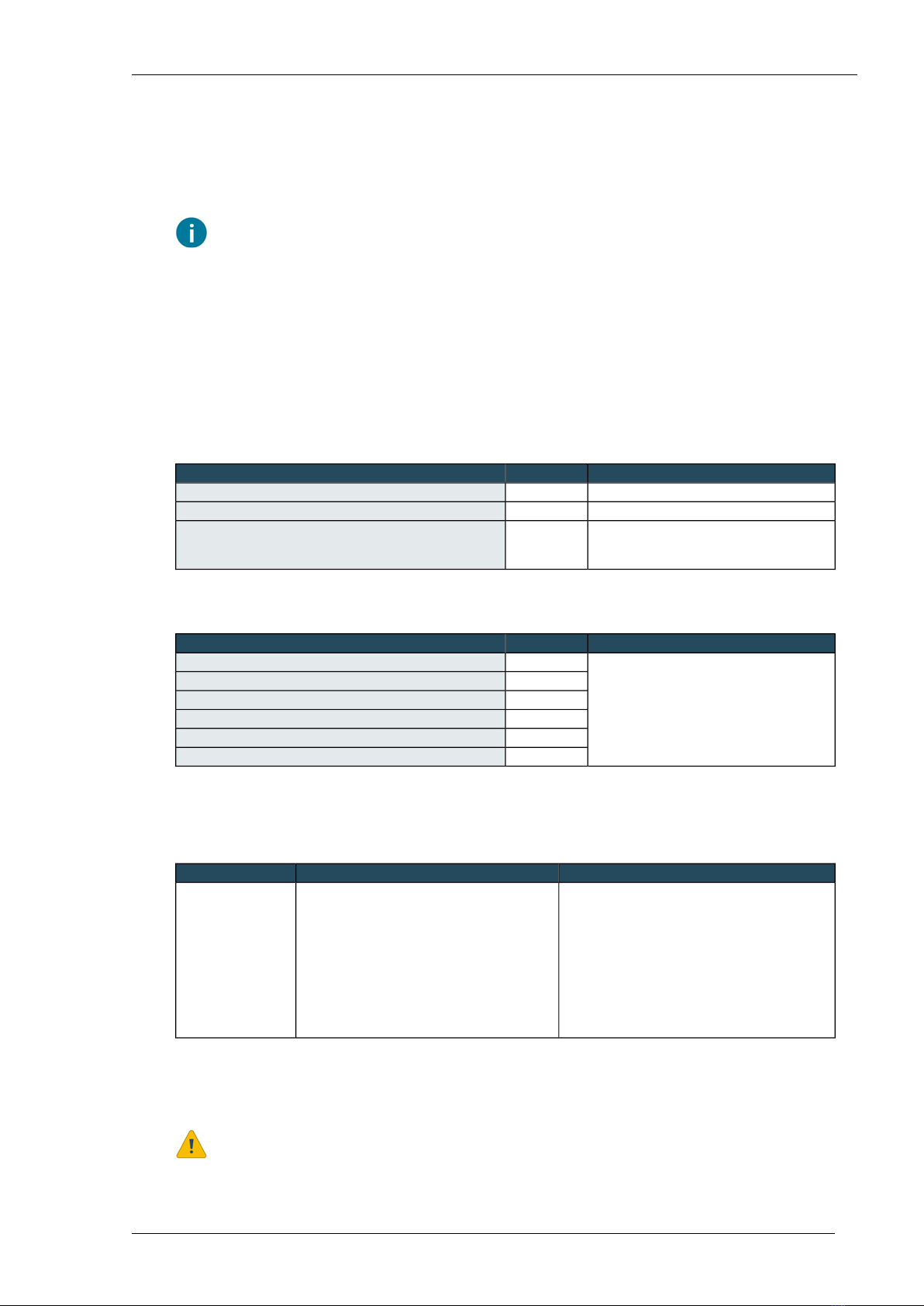
Compass system overview
A Compass system always consists of a Compass cabinet to which field equipment such as sensors
can be connected. On account of to the many different possible combinations of field equipment,
almost every Compass system will be different. Below there is an example of a comprehensive
configuration.
The Priva Compass price list gives an overview of the sensors and systems that are supported.
E. EC-DSS interfaceA. Compass cabinet
F. EC sensorB. Weather station
G. Drain sensor systemC. pH interface
H. Other sensorsD. pH sensor
The Compass cabinet is the heart of the Compass system. The Priva Blue ID controller in the Compass
cabinet controls the system and the sensors or actuators are connected to the inputs and outputs
of the Priva Blue ID modules. Sensors are connected directly to the inputs and outputs of the modules
or are connected via interfaces, such as the pH interface.
The components are supplied separately. An installer positions the separate components and
connects them to each other.
Installing Priva Compass - 00.01410
Priva
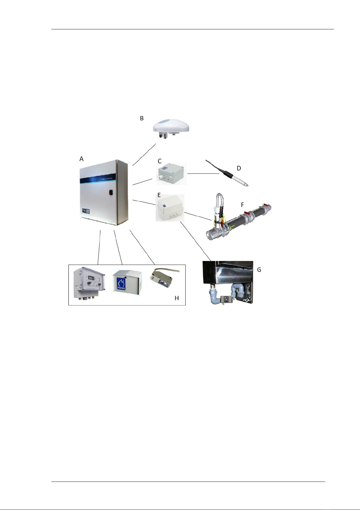
Compass cabinet components
The Compass cabinet consists of the following main components:
• a controller for controlling the system
• modules with inputs and outputs for connecting the sensors or interfaces
• a gateway for configuring the system or controlling the system via a smartphone
• power supplies for the components in the cabinet and the connected sensors
Compass 4S hardware configuration
E. 24 VDC system power supplyA. 0 V and 24 V connections (both VAC and VDC)
F. 24 VDC power supply field equipmentB. circuit breaker
G. DIN rail with controller and space for expansion modulesC. 24 VAC transformer
H. DIN rail with Mix I/O module and space for expansion
modules
D. 24 VAC fuse
11Installing Priva Compass - 00.014
Compass cabinet components
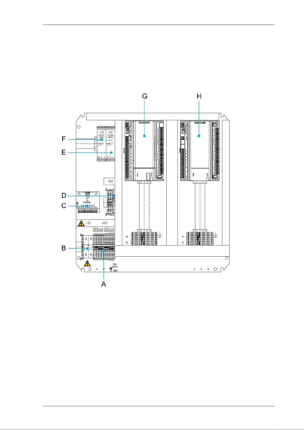
Compass 2S hardware configuration
E. 24 VDC system power supplyA. 0 V and 24 V connections (both VAC and VDC)
F. 24 VDC power supply field equipmentB. circuit breaker
G. DIN rail with controller and space for expansion modulesC. 24 VAC transformer
D. 24 VAC fuse
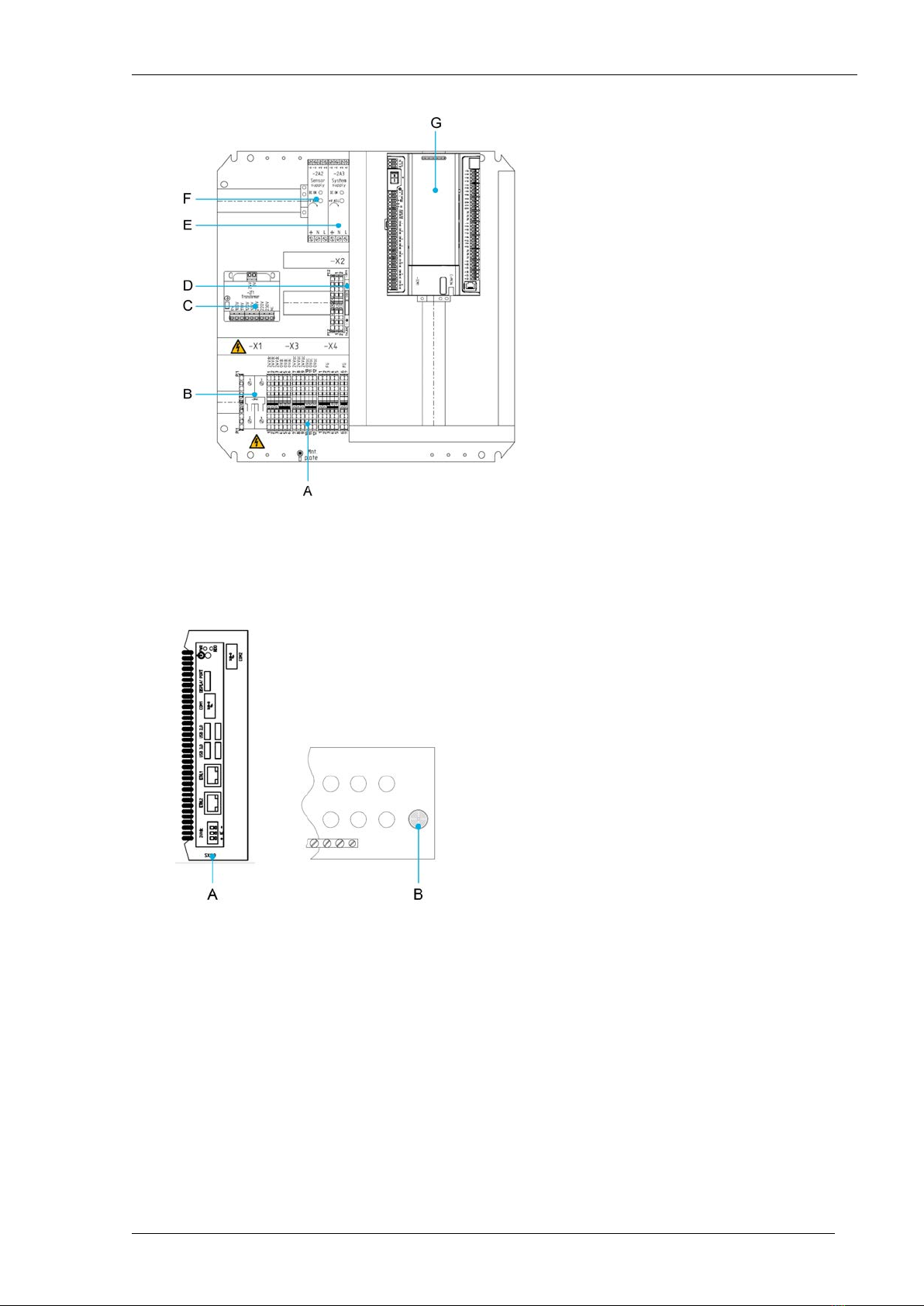
Door and underside of Compass 4S and Compass 2S
B. buzzer (on the bottom of the cabinet)A. Priva Gateway (mounted on the door)
Installing Priva Compass - 00.01412
Priva
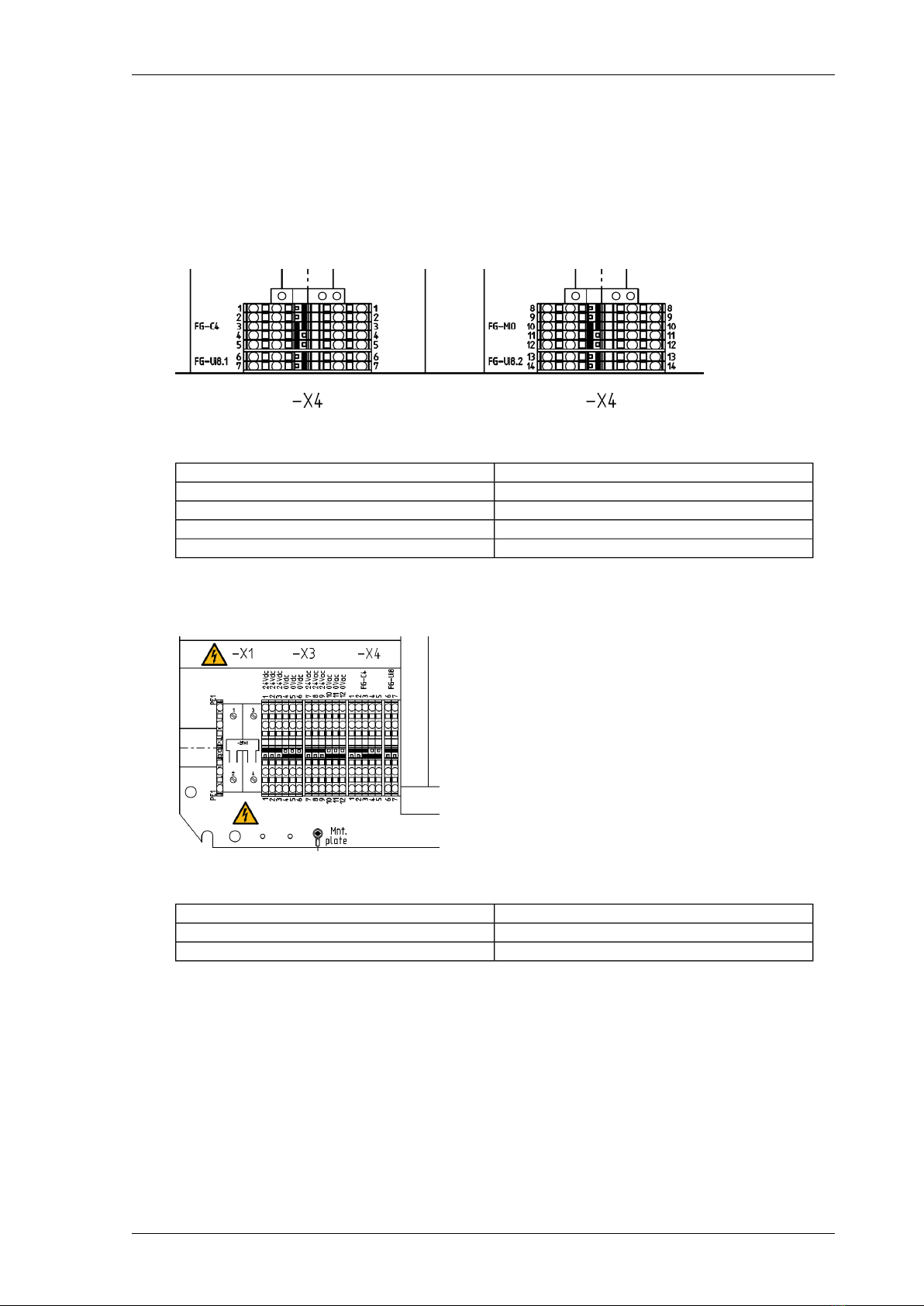
Compass FG terminals
The Compass cabinet has multiple sets of FG terminals. The FG terminals must not be used randomly.
The FG terminals are specific to the different modules in the cabinet. Extension modules are delivered
separately and must therefore be connected with the correct FG terminals after installation.
Compass 4S
FG terminals Compass 4S
ForFG terminals
C4 C-MX34 controllerX4.1 … X4.5
UI8 extension module 1X4.6 … X4.7
MX34 Mix I/O moduleX4.8 … X4.12
UI8 extension module 2X4.13 … X4.14
Compass 2S
FG terminals Compass 2S
ForFG terminal
C4 C-MX34 controllerX4.1 … X4.5
UI8 extension module 1X4.6 … X4.7
13Installing Priva Compass - 00.014
Compass cabinet components

Overview of connecting sensors and systems
The following sensors and systems can be used in a Compass system and can be connected to the
Compass cabinet.
Connect toArticle numberSensor, interface or system
RS485 input of Priva C43779240Weather station WSC11
universal input of a Priva Blue ID module3771351Weather interface WI2
24 VDC power supply
24 VAC power supply
3771009Meteorological station with:
Weather interface WI23779203Wind speed sensor
Weather interface WI23779204Outside temperature sensor
Weather interface WI23779206Rain sensor
Weather interface WI23779215Wind direction sensor
Weather interface WI23779205Linear light sensor LS2WI
0-50 mV
universal input of a Priva Blue ID module3779213Linear light sensor LS2 0-5 V
24 VDC power supply
24 VAC power supply
Weather interface WI23779207Solari / radiation sensor
potential-free contact, connect directly to the universal
input of a Priva Blue ID module
3779000Snow sensor
24 VAC power supply
4 … 20 mA, connect directly to the universal input of a Priva
Blue ID module
3779219Air humidity sensor
universal input of a Priva Blue ID module
24 VAC power supply
universal input of a Priva Blue ID module3771051EC-DSS interface ¹
24 VDC power supply
24 VAC power supply
EC-DSS interface3771052EC sensor, short, with NTC 1
kΩ/25°C (inline)
EC-DSS interface3771041EC sensor, long, with NTC 1
kΩ/25°C (angled)
EC-DSS interface3779224Drain sensor system
universal input of a Priva Blue ID module3771056pH interface
24 VDC power supply
24 VAC power supply
pH interface3779046pH sensor
universal input of a Priva Blue ID module3779024Priva Measuring Box T+RH ²
24 VDC power supply
24 VAC power supply
universal input of a Priva Blue ID module3779027Priva Measuring Box T
universal input of a Priva Blue ID module3795044Guardian CO2 monitor
90 … 260 VAC power supply (50 - 60Hz)
universal input of a Priva Blue ID module3779013Water temperature sensor
universal input of a Priva Blue ID module3779016Soil temperature sensor
universal input of a Priva Blue ID module3771140Priva Groscale weighing system
24 VDC power supply
24 VAC power supply
analogue output of a Priva Blue ID module3770170Dosing Channel Driver
24 VAC power supply
¹ connections for 2 EC sensors or 2 Drain sensor systems
² temperature sensor and relative air humidity sensor are connected separately
Installing Priva Compass - 00.01414
Priva

Compass system installation steps
General installation
The general installation steps for Compass are explained in the Compass insert sheet. The Compass
insert sheet is included in the box of the Compass cabinet.
The Compass insert sheet explains how to perform the following steps.
1. Suspension of the Compass cabinet.
2. Connect the power supply to the Compass cabinet.
3. Switch on the Compass system.
4. Connect the laptop and run the initial configuration.
5. Install extra Priva Blue ID hardware.
The insert sheet shows the basics of connecting field equipment, but cannot display details for all
field equipment. This manual provides additional information and details that are necessary for
installing and connecting field equipment, e.g. for commissioning (see Commissioning Compass
(page 23)).
To be able to commission a new Compass, both the Gateway and the controller must be
equipped with the latest version of the software. This software is available at
https://support.priva.com, under Priva Compass, in the article Where can I find the latest Priva
Compass software?. Save these files on your laptop.
Make sure you have a software licence, which can be purchased via web production.
Installing field equipment
Perform these steps to install and connect field equipment:
1. Install the weather station.
2. Install the pH sensor.
3. Position the pH interface.
4. Connect the pH sensor to the pH interface.
5. Connect the pH interface to the Compass cabinet.
6. Install the EC sensor.
7. Install the Drain sensor system.
8. Position the EC-DSS interface.
9. Connect the DSS to the EC-DSS interface.
10. Connect the EC sensor to the EC-DSS interface.
11. Connect the EC-DSS interface to the Compass cabinet.
12. Install other sensors.
13. Connect other sensors to the Compass cabinet.
14. Test the Compass system.
Position the Compass cabinet
De Compass cabinet is heavy. Lift the cabinet with 2 persons or use a suitable lifting device.
15Installing Priva Compass - 00.014
Compass system installation steps
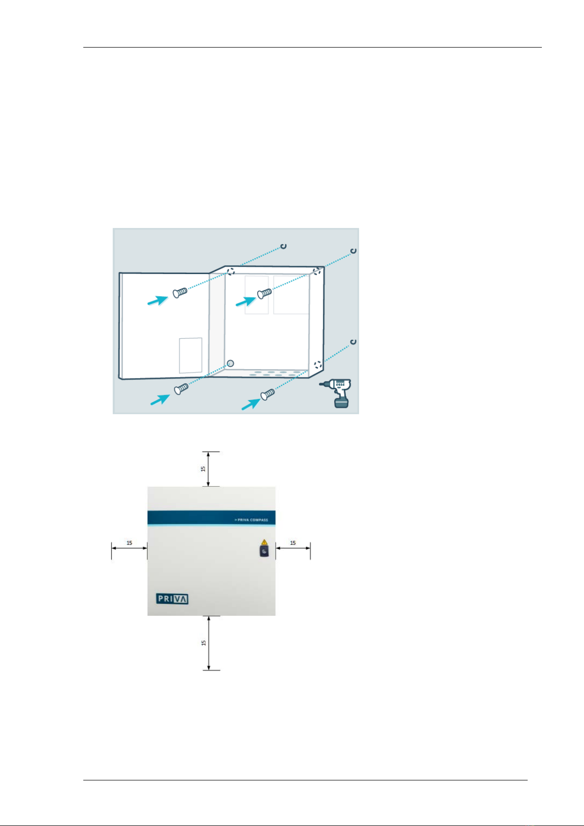
When positioning the cabinet, bear the following in mind:
• Position the cabinet against a wall or other solid background.
• Ensure there is sufficient space around the cabinet.
• Ensure there is sufficient space underneath the cabinet to feed the wiring through.
• Ensure there is sufficient space above and next to the cabinet for the dissipation of heat.
• Use the 4 specified mounting holes for installing the cabinet.
• Use M8 bolts or M8 screws that can bear the weight of the cabinet.
• The cabinet is heavy. Have more than one person hold the housing in the correct position while
placing it. Or use a suitable lifting device.
• Position the cabinet in a space that meets the environmental requirements.
• Make sure the space and the cabinet are easily accessible. There must be enough space to open
the cabinet for maintenance and installation. This is especially important if you need to switch
off the system with the circuit breaker in the event of problems.
Mounting holes
Recommended space (in cm) to be left free around the cabinet
Installing Priva Compass - 00.01416
Priva
Cable grommets and glands
The underside of the Compass cabinet has various types of cable grommets with cable glands. The
cable glands are intended for various types of cabling. Always use a cable grommet and gland that
is associated with a cable type with the specified cable diameter.
Always close a cable gland with a supplied dummy plug if a cable grommet is not being used.
Cable diameterCable typeNumberCable grommet /
gland
10 … 18 mmEthernet
optical fibre ¹
2PG21
6 … 12 mmmains power supply
other cabling
2M20
9 … 16 mmcabling for field equipment6 (Compass 2S)
10 (Compass 4S)
M25
¹ optional
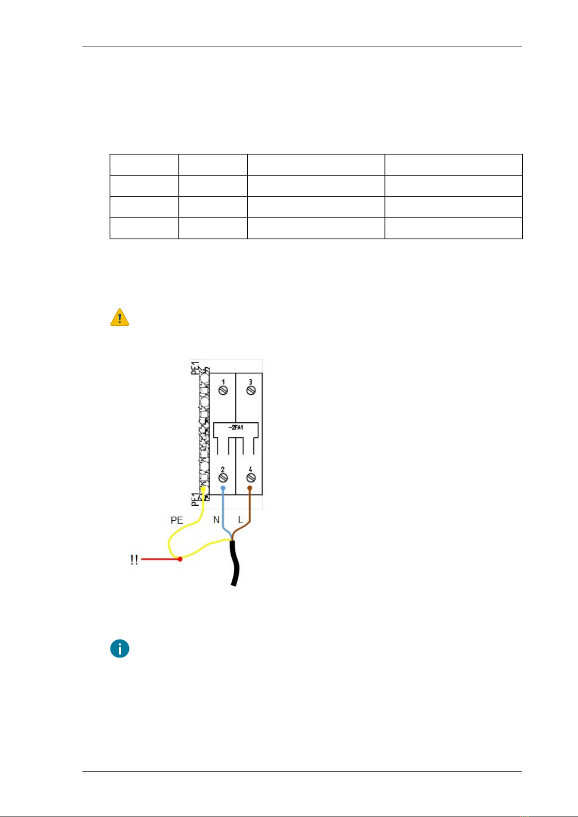
Connecting the mains cable
Always switch off the mains power supply when you are working on electrical connections.
L: Line (phase)PE: Protective Earth (ground)
!!: Length of earth wire = 2x length of phase wireN: Neutral
Use a mains cable with a diameter of 5 … 10 mm. This is suitable for the M20 cable gland.
17Installing Priva Compass - 00.014
Compass system installation steps

1. Strip around 10 cm from the outer sheath of the mains cable.
2. Cut the wires to length. Make sure the earth wire is twice as long as the phase wire and the
neutral wire.
3. Strip the wires.
4. Feed the mains cable through the M20 cable gland.
5. Connect the earth wire (PE) to the earth terminal next to the circuit breaker.
6. Connect the neutral wire (N) to input 2 of the circuit breaker.
7. Connect the phase wire (L) to input 4 of the circuit breaker.
8. Screw tight the cable gland.
If you need to disconnect the mains cable, first disconnect the phase wire (L) and neutral wire (N),
and then disconnect the earth wire (PE) last.
Installing Priva Compass - 00.01418
Priva
Table of contents
Popular Farm Equipment manuals by other brands

Alice's Garden
Alice's Garden BABETTE CKMC6 manual

Osborne
Osborne Big Wheel RN1 Series Assembly & operating instructions

Krone
Krone EasyCut F 280 Original operating instructions

Maschio
Maschio PANTERA Series Use and maintenance

LUCAS
LUCAS Castor 134 instruction manual

DEUTZ-FAHR
DEUTZ-FAHR SwatMaster 7131 EVO operating manual


