LMC Switch Plow 6300 Series Instructions for use

6300 SERIES
OWNER OPERATOR/PARTS MANUAL
MAY 2011
Lewis M. Carter Manufacturing Co., Inc.
Highway 84 West P.O. Box 428
Donalsonville, GA 39845
229-524-2197 1-800-332-8232
FAX 229-524-2531
Lewis M. Carter Manufacturing Co.
P.O. Box 21049
Carson City, NV 89721
888-459-9615 775-246-4555
866-585-6461 775-246-4512

6300 Updated 2011 Manual II

6300 Updated 2011 Manual III
TABLE OF CONTENTS
I. Introduction Page #
Pre-Delivery Checklist 1
Delivery Checklist 2
Replacement Parts Information 2
Model 6305 Standard Components 3
Model 6306 Standard Components 3
Model 6307 Standard Components 3
Model 6308 Standard Components 4
6300 Series Optional Components 4
II. Safety Precautions
Safety Precautions 5
Safety Symbols 6
Safety Instructions & Rules 7
Safety Sign Locations 8
III. Operations
Pre-Operations Checklist 9
Shear Bolt Standards 9
Sway Block Positions 9
Start-Up Procedures 10
Troubleshooting 11-12
IV. Assembly 6300 Series Switch Plow
Main Frame and Tool Bar 13-14
6300 Shank Spacing 15
Tool Bar Stops 16
Plow Shanks to Tool Bar 17
Mold Boards to Shanks 18
Bolt Torque Charts 19
Gauge Wheel and Gauge Wheel Arm Assembly 20
Front Gauge Wheel Assembly 21
Changing 6305 to 6306 22
Changing 6305 to 6307 23-24
Changing 6305 to 6308 25-26
Changing 6306 to 6307 27
Changing 6306 to 6308 28-29
Changing 6307 to 6308 30-31

6300 Updated 2011 Manual II
TABLE OF CONTENTS
(CONT’D.)
V. Parts Listing
Main Frame and Tool Bar 32-33
Front Shank 34
Intermediate Shank 35
Mold Boards with Small Slides 36
Mold Boards with Long Slides 36
Rear Gauge Wheel 37
Gauge Wheel Arm Assembly 38
SMV Warning Sign 39
Front Gauge Wheel 40-41
1Bottom Extension Kit 42
2Bottom Extension Kit 43
Maintenance Record 44
VII. Warranty Back Page

1
INTRODUCTION
Before operating the Switch Plow, study this manual carefully to become familiar with
the Operation and Safety Procedures. Failure to do so could result in personal injury or damage
to the equipment.
All measurements in this manual are in U.S. Standard Units.
The right and left side is determined by facing the direction of travel when in use.
The Warranty Certificate is included in this manual and supplied to owner at time of
purchase
.
PRE-DELIVERY CHECKLIST
Plow should be assembled and in proper operating condition before delivery to customer.
Plow has been assembled according to manufacturer’s instruction.
Landslides, mold boards and all other hardware have been installed properly and
tightened to specifications.
All moving parts have been lubricated properly and all grease fittings will take
grease.
All functions of plow are working as designed by manufacturer.
All safety decals are located in proper places.
Clean and touchup any scratches in paint.
Be sure dealer rep has fully explained proper setup operation of plow.
Signature and date of technician performing work.
Set-up Technician Date of Service

6300 Updated 2011 Manual 2
DELIVERY CHECKLIST
ADVISE CUSTOMER OF THE FOLLOWING AT THE TIME OF DELIVERY
:
Regular lubrication and maintenance extend life of equipment.
Always follow safe and proper operating procedures.
Point out warning decals and safety hazards.
Keep all bolts tightened to specifications.
Use safety and warning lights when transporting plow on public roads.
Fill out delivery and warranty forms, and have customer sign.
Show and explain to customer how to hitch plow to tractor, make field adjustment and operate correctly
accordingly to operator’s manual.
Set-Up Technician Date
When ordering replacement parts, from your dealer, refer to Model No. and Serial No. of your Switch
Plow.
Serial No.:
Model No.:

6300 Updated 2011 Manual 3
MODEL 6300 SWITCH PLOW REQUIRED COMPONENTS
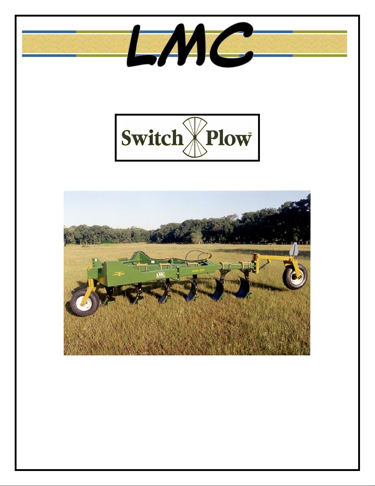
MODEL 6305 STANDARD SWITCH PLOW – 5 BOTTOM ON – LAND
COMPONENT BUNDLE BUNDLE NO. NO. REQ’D
Main Frame 84-001-63 1
Tool Bar – 6 Bottom 85-005-63 1
Mold Board with Small Slides 83-003-36 4
Mold Board with Long Slides 83-206-36 1
Front Shank 83-212-36 1
Intermediate Shank 83-213-36 3
Gauge Wheel Arm 84-004-63 1
SMV Warning Sign 83-031-36 1
Rear Gauge Wheel Yoke Assy 84-002-63 1
Front Gauge Wheel 84-003-63 2
MODEL 6306 STANDARD SWITCH PLOW – 6 BOTTOM ON – LAND
COMPONENT BUNDLE BUNDLE NO. NO. REQ’D
Main Frame 84-001-63 1
Tool Bar – 6 Bottom 85-005-63 1
Mold Board with Small Slides 83-003-36 5
Mold Board with Long Slides 83-206-36 1
Front Shank 83-212-36 1
Intermediate Shank 83-213-36 3
Gauge Wheel Arm 84-004-63 1
SMV Warning Sign 83-031-36 1
Rear Gauge Wheel Yoke Assy 84-002-63 1
Front Gauge Wheel 84-003-63 2
MODEL 6307 STANDARD SWITCH PLOW – 7 BOTTOM ON – LAND
COMPONENT BUNDLE BUNDLE NO. NO REQ’D
Main Frame 84-001-63 1
Tool Bar – 6 Bottom 85-005-63 1
1 – Bottom Extension Tool Bar 85-015-63 1
Mold Board with Small Slides 83-003-36 5
Mold Board with Long Slides 83-206-36 1
Front Shank 83-212-36 1
Intermediate Shank 83-213-36 3
Gauge Wheel Arm 84-004-63 1
SMV Warning Sign 83-031-36 1
Rear Gauge Wheel Yoke Assy 84-002-63 1
Front Gauge Wheel 84-003-63 2

6300 Updated 2011 Manual 4
MODEL 3600 SWITCH PLOW REQUIRED COMPONENTS
MODEL 3608 STANDARD SWITCH PLOW – 8 BOTTOM ON – LAND
COMPONENT BUNDLE BUNDLE NO.
NO. REQ’D
Main Frame 84-001-63 1
Tool Bar – 6 Bottom 85-005-63 1
2 – Bottom Extension Tool Bar 85-014-63 1
Mold Board with Small Slides 83-003-36 5
Mold Board with Long Slides 83-206-36 1
Front Shank 83-212-36 1
Intermediate Shank 83-213-36 3
Gauge Wheel Arm 84-004-63 1
SMV Warning Sign 83-031-36 1
Rear Gauge Wheel Yoke Assy 84-002-63 1
Front Gauge Wheel 84-003-63 2
MODEL 3600 SWITCH PLOW OPTIONAL COMPONENTS
COMPONENT BUNDLE BUNDLE NO.
NO. REQ’D
Wear Shin Multi-Life 79-208-36 A/R
Front Shank 83-204-36 1
Intermediate Shank 83-205-36 A/R
1Bottom Extension Kit 72-003-36 1
2Bottom Extension Kit 72-004-36 1
Front Spring Trip Shank 83-218-36 1
Intermediate Spring Trip Shank 83-219-36 A/R
Reverse Intermediate Spring Trip Shank 83-220-36 A/R
Spring Trip Shank Mold Board with Small Slides 83-216-36 A/R
Spring Trip Shank Mold Board with Long Slides 83-217-36 1

6300 Updated 2011 Manual 5
SAFETY PRECAUTIONS
1. Always operate plow in a careful, controlled manner.
2. Always lower plow to ground when not in use.
3. Stand clear of Switch Plow when being raised or lowered.
4. Never operate plow from side to side while someone is standing inside main frame.
5. All personnel should stand clear of Switch Plow during preparation for movement of equipment
from one location to another.
6. Always stand clear of plow when being operated from side to side.
7. Always place tool bar in center of main frame before unhitching from tractor.
8. Do not park vehicles or place objects within 10 feet of the rear of the Switch Plow.
9. Always park plow on flat, level ground before unhooking from tractor.
10.. When transporting plow, always make sure tool bar is in center position and hydraulic cylinder
hoses are connected to tractor outlets so plow cannot swing from side to side during transit.
11. Turn on flashing lights when transporting unit on highway, unless prohibited by law.
12. Never check for hydraulic leaks with hands or clothes.
13. Do not operate hydraulic systems when hydraulic leaks are present.
14. Do not operate unit close to high voltage electric lines.

6300 Updated 2011 Manual 6
SAFETY SYMBOLS
RECOGNIZE SAFETY INFORMATION
This is the safety symbol. When you see this, it means:
ATTENTION!
BECOME ALERT!
YOUR SAFETY IS INVOLVED!
Follow recommended precautions and procedures.
UNDERSTAND SIGNAL WORDS
A signal word –DANGER, WARNING, or
CAUTION – is used with the safety alert symbol.
DANGER indicates imminently hazardous situations that,
if not avoided, will result in serious injury, or death.
WARNING indicates potentially hazardous situations that,
if not avoided, could result in serious injury, or death.
WARNING may also be used to alert against unsafe practices. WARNING
CAUTION indicates potentially hazardous situations that,
If not avoided, may result in minor or moderate injury.
CAUTION may also be used to alert against unsafe practices. CAUTION
DANGER
FOLLOW SAFETY INSTRUCTIONS
Carefully read all safety messages in this manual and on your machine safety signs. Keep safety signs
in good condition. Remove missing or damaged safety signs. Contact LMC Bainbridge for
replacement parts.
Learn how to operate the machine and how to use controls properly. Do not let anyone operate without
instruction.
Keep your machine in proper working condition. Unauthorized modifications to the machine or
disrepair may impair safety, or the machine function.

6300 Updated 2011 Manual 7
SAFETY INSTRUCTIONS AND RULES
KEEP RIDERS OFF MACHINE
Only allow the operator on the machine. Keep riders off.
Riders on machine are subject to injury such as being struck by foreign objects and
being thrown off the machine. Riders also obstruct the operator’s view resulting in the
machine being operated in an unsafe manner.
OPERATOR’S MANUAL
Do not put this operator’s manual away unread. Read the manual carefully regardless
of previous experience. Allow yourself this time, it will save time and labor later on.
IMPORTANT: Keep an extra copy of the operator’s manual in your office or in
the garage in case one gets lost.
An extra copy may be acquired from your dealer for an extra fee.
PREPARE FOR EMERGENCIES
Be prepared if fire starts.
Keep a first aid kit and fire extinguisher handy.
Keep emergency numbers for doctors, ambulance service, hospital and fire department
near your telephone.
AVOID HIGHPRESSURE FLUIDS
Escaping fluid under pressure can penetrate the skin causing serious injury. Relieve
pressure before unhooking hydraulic or other lines. Tighten all connections before
applying pressure. Keep hands and body away from pinholes and nozzles that eject
fluids under pressure. Use a piece of cardboard to search for leaks.
If any fluid is injected into the skin, a doctor familiar with this type injury must
surgically remove it within a few hours or gangrene may result.

6300 Updated 2011 Manual 8
SAFETY SIGN LOCATIONS
READ ALL SAFETY DECALS CAREFULLY
Detaching Decal: Located on Center Mast of Main Frame.
Tool Bar Guide Decal: Located on Right and Left Front Side of Tool Bar Guide
.
Gauge Wheel Decal: Located on Each Side of Gauge Wheel Arm
Tool Bar Guide Danger Decal: Locate One Decal on Left & Right Front Side of Tool Bar Guide

6300 Updated 2011 Manual 9
OPERATIONS
PRE-OPERATIONS CHECKLIST
All tractor preparation should be as recommended in your Tractor Operator’s Manual. Tractor
should be fully weighted in accordance with Tractor Manufacturer’s recommendations.
1. Tractor has been prepared according to Tractor Operator’s Manual and Start-Up
Procedures on page 8.
2. Tractor Sway Blocks are in position as recommended in section on “Sway Block
Positions”.
3. The Plow has been prepared and properly attached to tractor and is operating as designed.
4. Adjust both lift links on tractor to same length.
5. Grease main tool bar pivot pin (every 8 hours).
6. Grease gauge wheel yoke pivot (every 8 hours).
7. Check gauge wheel bearings for loose play weekly (tighten or replace if necessary).
8. Check plow shanks for proper spacing (28” center to center for 18” cut).
9. Check all hydraulic hose connections for leaks and operate tool bar back and forth to
remove air from lines.
10.Keep all nuts and bolts tight. Check upon delivery and weekly thereafter.
SHEAR BOLT STANDARDS
The Switch Plow is equipped with 3/8” UNC x 4 ½” Grade 5 shear bolts in each shank. When
the bottom hits a hard object, the bolts will shear, permitting the plow bottom to trip and swing
backwards. Reset by raising plow and pushing bottom back to operating position and replacing
shear bolt.
SWAY BLOCK POSITIONS
Each bottom plow is equipped with a landslide, which helps the plow to run straight. The
landslides can be turned upside-down for additional wear time. Side draft control can also be
controlled by the position of the tractor sway blocks.
6300 ONLAND SERIES
Install sway blocks in up position to allow side sway when working and to prevent side sway
when the plow is raised for turning or transporting.

6300 Updated 2011 Manual 10
STARTUP PROCEDURES
IMPORTANT!
MAKE SURE CYLINDER IS ADJUSTED PROPERLY SO THAT BEAM
TOUCHES BOTH SIDES OF FRAME, OTHERWISE, IT COULD DAMAGE
CYLINDER
.
NOTE: All tractor preparations should be as recommended in your Tractor
Operator’s Manual. Tractor should be fully weighted in accordance with
Tractor Manufacturer’s recommendations.
1. Make sure rear end side duals have water in them.
2. Full set of weights on front of tractor.
3. Make sure the lift arms on the tractor are extended out at least 3 to 4 inches otherwise,
front plows will not take the ground. If necessary, extend out more. For on land plows
(shear bolt and spring trip) hook lift arms in top or bottom holes and make sure lift arms
are extended out enough to make plow go into the ground.
4. Swing plow from side to side and make sure that the tool bar touches both sides of frame.
If necessary, adjust clevis on cylinder. It is important that this is done; otherwise, it could
damage the cylinder.
5. Swing tool bar to center of frame. Lift off the ground until rear plow barely touches the
ground, and then adjust top length until front plow is off the ground by approximately 2
inches. This sets top link on tractor to proper length.
6. Set rear gauge wheel adjusting screw to preferred depth.
7. Adjust front gauge wheel to highest position before starting plowing operation.
8. Stabilizer bars should be turned up.
9. If plow tries to pull tractor around, let top link out 1 to 2 rounds. If plow continues to
pull, shim slide on rear plow approximately ¾” to 1”, slide to slide mount bracket. If this
continues, shim slide on second plow from rear approximately ¾” to 1” and slide to slide
mount bracket.
10.Do not use stabilizers on any on-land plow.
REVERSING THE PLOW
Raise plow slowly and reverse tool bar completely to opposite side of main frame. Turn tractor
around and slowly lower plow to ground and continue plowing.
CAUTION: NEVER SHIFT PLOW WHILE IN GROUND!!

6300 Updated 2011 Manual 11
TROUBLE SHOOTING
PROBLEM CAUSE SOLUTIONS
Plow will not go in ground: Tractor depth control too shallow
Insufficient plow bottom suction.
Worn plow shares
Incorrect rockshaft setting.
Severe hard ground conditions
Spring trip shank mold board tilt
not set properly.
Front gauge wheels not set
properly.
Adjust tractor setting.
Shorten center link on tractor and
extend lift arms outward.
Replace with new shares.
Adjust on tractor.
Tilt gangs forward to rear shear
bolt position.
Adjust each trip spring shank jam
nuts in to move shank and mold
board forward to take more ground.
Set plowing depth and adjust front
gauge wheels to run on top of
ground.
Poor depth control: Too much load response.
Worn shares.
Adjust sensitivity lever on tractor.
Replace sensitivity lever on tractor
Plow not running straight: Improper lateral adjustment.
Plow running on nose.
Check right and left hand link for
the same dimension.
Check tractor wheel setting and tire
wear.
Check for excess land-slide wear.
Adjust center link on tractor and/or
rear gauge wheel on plow.
Ridging:
Plow not properly level laterally.
Plow not level for & aft.
Front bottom cutting too wide or
too narrow.
Both right and left hand lift links
should have the same dimensions.
Adjust tractor center link and/or
rear gauge wheel adjustment.
Check for equidistant wheel
settings.
Check for incorrect distance of
tractor from last water furrow.

6300 Updated 2011 Manual 12
TROUBLE SHOOTING
PROBLEM CAUSE SOLUTIONS
High draft: Plow running on nose.
Too little load response.
Insufficient traction.
Adjust center link and/or rear
gauge wheel setting.
Adjust rockshaft lever.
Increase tire or tractor weight.
Poor trash covering: Incorrect tractor speed.
Too much trash on ground.
Adjust to proper speed (4-5 mph) in
normal soil conditions.
A light harrowing or mowing may
be necessary.
Standard trip too often for soil
conditions:
Improper shear bolt. Switch to 3/8” x 4 ½” grade 5 shear
bolt.
Spring Trip Shanks trip too often
for soil conditions:
Improper setting on Trip tension. Adjust each shank from front to
back by increasing spring tension
with jam nuts.

6300 Updated 2011 Manual 13
ASSEMBLY INTRUCTIONS
6300 SERIES SWITCH PLOW
MAIN FRAME AND TOOL BAR (REFER TO FIGURE 2)
The main frame will come completely assembled with the required hydraulics factory
installed. The 6-Bottom tool bar will be shipped separate and will require assembly
.
CAUTION
:
The Main Frame should be supported by adequate floor supports that will support
the weight of the frame and any added plow components
Es necesario soportar el armazon principal suficientemente para soportar las
armazon tambien con el pest de las otras adiciones del arado.
Remove the tool bar pivot pin from the main frame and clean paint from both the pivot
pin and pivot hole. Apply a good layer of grease to the pivot pin and pivot hole through
main frame.
Insert the tool bar into the main frame and replace the pivot pin. (Refer to Figure 2).
Move the tool bar to the center of the main frame and attach the main hydraulic cylinder
to the tool bar. The cylinder cap end will come from the factory attached to the main
frame and should be checked for proper assembly.
NOTE:
Model 6308 requires the use of a counter-balance valve, which is mounted to the main
frame hitch. Connect hoses to the main cylinder and counter balance valve as shown in
Figure 2. Install the short hydraulic hose bracket to the tool bar pivot pin using (2) two
3/8 UNC x 1” long hex bolts and attach the hydraulic hoses to the bracket with the hose
clamps. Refer to Figure 2.

6300 Updated 2011 Manual 14
6300 SERIES MAIN FRAME AND TOOL BAR
(FIGURE 2)

6300 Updated 2011 Manual 15
SHANK SPACING AND DIRECTION
FOR ALL 6300 SERIES PLOWS
(FIGURE 3)

6300 Updated 2011 Manual 16
6300 SERIES TOOL BAR STOPS
84-005-63
This manual suits for next models
4
Table of contents
Other LMC Farm Equipment manuals
Popular Farm Equipment manuals by other brands

Fast
Fast A10 owner's manual

WilTec
WilTec 62614 Operation manual

Blue Diamond
Blue Diamond POWER RAKE Operation and maintenance manual

Kerbl
Kerbl Duo 18810 Instructions for use

Haybuster
Haybuster ROCK-EZE H-106 Operating Instructions and Parts Reference

GREAT PLAINS
GREAT PLAINS Ultra-Till I 3030 Series Operator's manual