Prizelawn PS 200 II User manual

OWNER’S MANUAL
Prizelawn
PrizelawnPrizelawn
Prizelawn
®
® ®
®
PS
PSPS
PS
200
200200
200
II
IIII
II
Power Spreader
TM
Shown with optional Side
Deflector installed

TABLE OF CONTENTS
Assembly Instructions…………………………...Section 1
Safety Precautions………………………………..Section 2
Training……………………………………………..Section 3
Preparation…………………………………………Section 4
Operation…………………………………………...Section 5
Operating Instructions…………………………...Section 6
Spreader Operation Instructions……………….Section 7
How to Determine Settings & Swath Width….. Section 8
Spreader Rate Setting Conversions……………Section 9
Maintenance, Adjustments, & Storage...………Section 10
Parts List…………………………………………….Section 11
Warranty……………………………………………..Section 12
Technical Specifications………………………….Section 13
Notes…………………………………………………Section 14
2.

1.1
Parking brake is engaged for shipping.
Disengage brake before removing unit from carton.
Install Upper Handle Assembly to Main Frame using (4)
5/16-18 x 1 1/2” SS. Hex Bolts washers and Lock Nuts
as shown. Install the one washer on the outside of
the Frame and on the outside of the Upper Handle
with each bolt.
1.2
Slide the hole in the bottom of
Hopper over the impeller shaft and
attach hopper to Frame using the front
two (2) holes in Hopper with two (2) 1/4-
20 x 5/8 Hex Bolts, Washers, and Lock
Nuts, but do not tighten. NOTE: the two
(2) Screen Retaining Clips are installed in
the back two (2) holes with two (2) 1/4-20
x 5/8 Hex Bolts, Washers, and Lock Nuts
as shown but do not tighten. Center the
Impeller Shaft in the hole in the Hopper.
Tighten all the bolts. From inside the
Hopper, install the 3/8” ID. Flat Washer
over the Impeller Shaft. Insert Agitator
Wire into hole in the Impeller Shaft as
shown. Install Hopper Screen under
Screen Retaining clips previously
installed.
1. Assembly:
3.
5/16-18 x 1 1/2”
Hex Bolts &
Lock Nuts
Impeller Shaft
Front Holes
Inside Hopper
Back Holes
Inside Hopper
Screen
Retaining Clip (2)
3/8” ID. Flat
Washer
Agitator Wire
Upper
Handle
Parking Brake
Control
Panel
#10-24 x 5/8”
Screw (4)
1.3
Install Control Panel with the
Spreader On/Off Assembly and the
Throttle Cable attached to the engine
onto the Upper Handle using four (4)
#10-24 x 5/8” Pan Hd. Screws. Tighten
securely.
Install a washer on the
outside of frame and the han-
dle brace w/ each bolt

1.5
Slide Transmission Cable into Bracket on
Upper Handle as shown. Center the threads
above and below the Bracket and tighten Nuts
securely.
1. Assembly-Continued:
Transmission
Cable
Transmission
Cable Nuts
Handle Bracket
4.
1.6
Thread the Yoke and Locking Nut onto the
end of the Transmission Cable. Attach to the
Forward/Reverse Lever Bracket in the hole
shown using a 3/16” dia. Clevis Pin. (the second
hole shown is an optional attachment point).
Adjust Yoke so the Forward/Reverse Lever
is straight up in relation to the upper handle
in the neutral position. Check operation of
Forward/Reverse Lever. It should operate
smoothly. When complete, secure the Clevis
Pin with 3/16” Dia. Cotter Pin.
1.4
Place bent end of the Main Shutoff
Connecting Rod through the hole in the Pivot Lever
on the Hopper. Secure Rod with a Hitch Pin Cotter
as shown.
Thread a 5/16-18 Hex nut onto thread on
opposite end of Rod until it stops. Insert rod through
the pivot arm on the lever as shown. Thread
second nut up to the pivot arm: do not tighten. Pull
the shutoff lever to the closed position and look
inside hopper to see if the port holes are closed.
Adjust top nut in small increments until the holes
are just closed. CAUTION-DO NOT ADJUST THE
NUT TOO FAR DOWN AS DAMAGE CAN
OCCUR. When ports are completely closed, thread
bottom nut up and tighten both nuts.
Clevis &
Cotter Pin
Yoke &
Locking Nut
Forward/Reverse
Lever Bracket
Main Shutoff
Connecting
Rod
Hitch Pin Cotter
Pivot Lever
Main Shutoff
Connecting
Rod
Pivot Arm
5/16-18 Hex
Nuts
Equal Threads
on each side of
nuts

2. Safety Decals
Specific safety warning decals are located on the equipment near the immediate areas of potential
hazards. These decals should not be removed or obliterated. Replace them if they become non-readable.
5

This is the operator’s manual for your Prizelawn
®
PS 200
ll
TM
. The owner’s manual for the engine of the
spreader is separately enclosed. Keep the engine owner’s manual with this manual for future reference. Requests
for replacement engine manuals and questions regarding your engine should be directed to the engine
manufacturer.
2.1 SAFETY:
This Safety Alert Symbol is used both in this manual and on the machine to identify important safety messages
which must be followed to avoid accidents.
The safety alert symbol appears above information which alerts you to unsafe actions or situations and will be
followed by the word DANGER, WARNING, or CAUTION.
DANGER—Indicates an imminently hazardous situation which, if not avoided, will result in death or serious injury.
WARNING—Indicates a potentially hazardous situation which, if not avoided, could result in death or serious injury.
CAUTION—indicates a potentially hazardous situation which, if not avoided, may result in minor or moderate injury.
Read the Operator’s Manual and other training material. If the operator(s) or mechanic(s) cannot read English it is
the owner’s responsibility to explain this material to them.
Become familiar with the safe operation of the equipment, operator controls, and safety signs.
All operators and mechanics should be trained. The owner is responsible for training the users.
Never let children or untrained people operate or service the equipment. Local regulations may restrict the age of
the operator.
The owner/user can prevent and is responsible for accidents or injuries occurring to themselves, other people or
property.
Never leave a running machine unattended.
Evaluate the terrain to determine any potential risks to stability prior to operating.
Inspect the area where the equipment is to be used and remove all objects such as rocks, toys, and wire which can
destabilize the machine.
Wear appropriate clothing including hard hat, safety glasses and hearing protection. Long hair, loose clothing or
jewelry may get tangled in moving parts.
Do not exceed weight capacity of hopper.
Use extra care when handling gasoline and other fuels. They are flammable and vapors are explosive.
Use only an approved container
Never remove gas cap or add fuel when engine is running. Do not smoke.
Never refuel or drain the machine indoors.
Check that operator’s presence controls, safety switches and shields are attached and functioning properly. Do
not operate unless they are functioning properly. 6.
3.Training:
4. Preparation:

Engine parts, especially muffler, become
Extremely hot.
Severe burns can occur.
Allow parts to cool before touching.
6. Operating Instructions:
FAMILIARIZE YOURSELF WITH ALL CONTROLS PRIOR TO OPERATING. REFER TO THE FOLLOWING ILLUSTRATIONS:
Forward Ground Speed: Located on right hand lever. Pull lever towards operator to increase speed. SLOWLY
release lever to decrease ground speed. Release lever completely to stop movement.
Reverse Ground Speed: Located on Left hand lever. Pull lever towards the handle bar to increase speed. SLOWLY
release lever to decrease ground speed. Release lever completely to stop movement.
Throttle Control: The cable is linked to engine throttle for controlling engine speed. Move lever forward to increase
engine rpm, move lever rearward to decrease engine rpm. Move lever all the way rearward to shut off engine.
Choke Control: The throttle control is linked to the engine choke. Move the lever all the way forward to engage.
Ground Speed Control: Located on the right hand side of the control panel. Loosen knob and move plate to
limit the movement of the forward ground speed lever to achieve desired ground speed.
5. Operation:
This machine shall not be operated without all guard(s), shield(s), and cover(s) in place.
Never run an engine in an enclosed area.
Only operate in good light, keeping away from holes and hidden hazards.
Be sure all drives are in neutral before starting engine.
Only start engine from the operator’s position.
Be sure of your footing and wear proper footwear while using.
Be aware of potential for reduced footing in wet or muddy conditions.
Slow down and use extra care on hillsides. Take care in changing directions on slopes. Tip-overs can occur with
sudden stops when operating straight down hill-sides.
Turf conditions can affect the machine’s stability.
Use caution while operating near drop-offs
Slow down and use caution when making turns and when changing directions on slopes.
Never operate with shields or guards not securely in place.
Do not change the engine governor setting or over speed the engine.
Stop on level ground, shut off engine before leaving the operator’s position for any reason including reloading the
hopper or unclogging or cleaning the spreader mechanism.
Stop equipment and inspect after striking objects or if an abnormal vibration occurs. Make necessary repairs before
resuming operations.
Keep hands and feet away from the spreader mechanism and other moving parts.
Look behind and down before backing up to be sure of a clear path.
Never carry passengers and keep pets and bystanders away.
Slow down and use caution when making turns and crossing roads and sidewalks.
Do not operate the machine on slopes greater than 15 degrees.
Be aware of the spreader discharge direction and do not intentionally point it at anyone.
Do not operate under the influence of alcohol or drugs.
Use care when loading or unloading the machine into a trailer or truck.
Use care when approaching blind corners, shrubs, trees, or other objects that may obscure vision.
Performance and response of machine may vary as weight of hopper contents changes.
7.

Directional Controls: Handle bars are moved to pivot the unit and steer the in the desired direction.
Spreader On/Off Control: Located in the LH. side of the control panel. Push lever to open spreader, pull back to
close.
Spreader-Rate Control: Located on the upper portion of the back of the spreader hopper. See rate setting section.
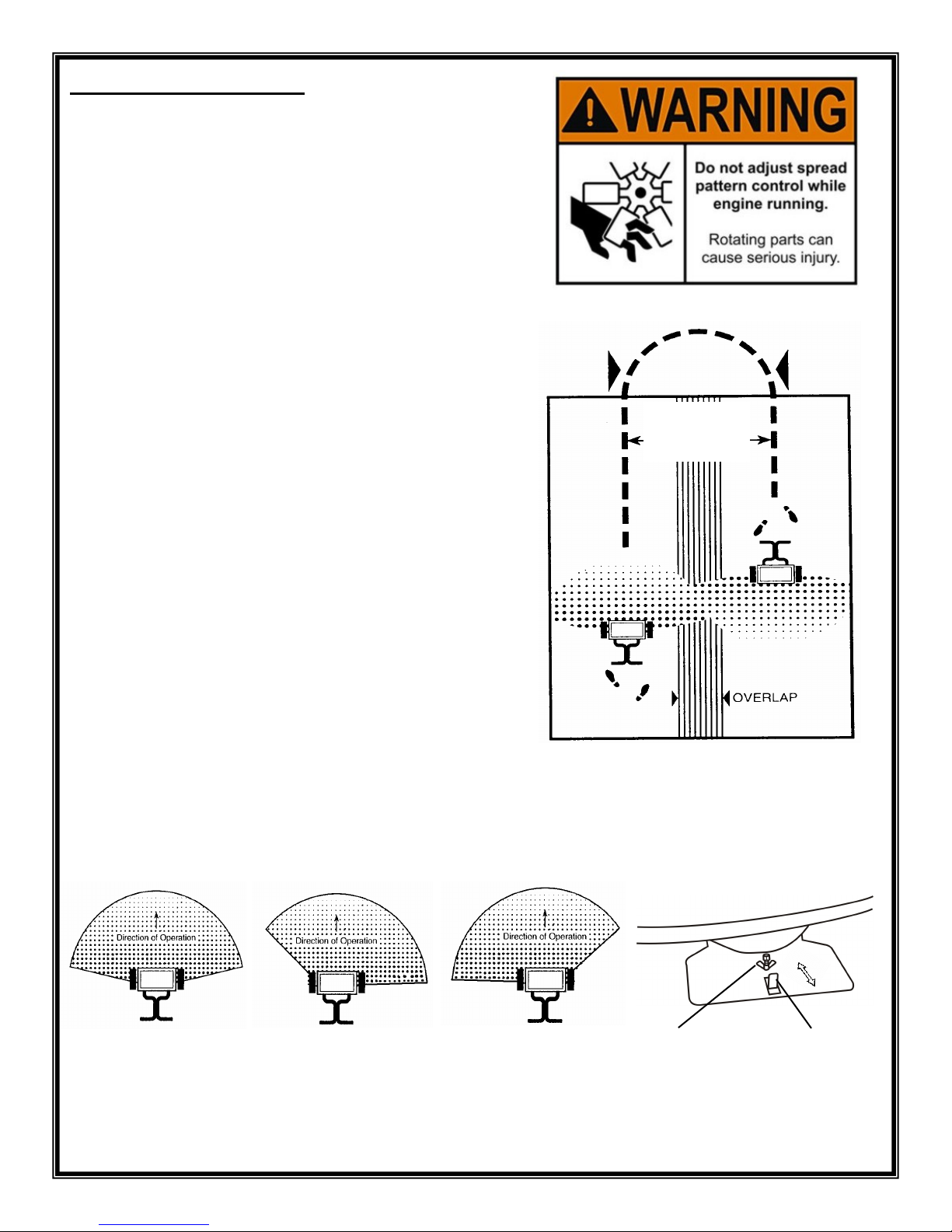
Spread Pattern Control: Located on the front of the hopper above the impeller. See pattern control section.
Drive Wheel Release: Located on the L.H. side of the machine near the front L.H. wheel. Release is used to release
drive system to allow machine to be pushed without engine running. Pull rod out and hook latch to allow machine to be
pushed without engine running.
Parking Brake Engagement: Located on the back of main frame. Push rod in and hook latch to engage parking
brake.
8.
Broadcast
Spreader
Rate Control
Parking Brake-
Push in & Lock
to Engage
Drive Wheel
Release -Pull Out &
Lock to Engage
Spread Pattern
Control
Forward Ground
Speed Control
Directional
Control
Throttle/Choke
Control
Spreader On/
Off Control
Directional
Control
Reverse Ground
Speed Control
When transporting spreader from location to location,
make sure the spreader on/off control lever is in the
“OFF” position.
Use Swath Width
on Package or Adjust
per Operator’s
Ground Speed
Normal spreading of material requires no adjustment unless otherwise stated on the package. In those cases where
the spread pattern has shifted, the pattern can be adjusted. If the pattern is heavier to the right (as viewed from the
operating position), loosen the wing nut and move the control plate in toward the hopper. If it is heavy to the left, move
the control plate out away from the hopper. Tighten wing nut after each adjustment is made.
7. Spreader Operation:
Check the product package for the rate setting (letter), pattern
setting (number), and recommended swath width. Loosen the
rate control knob and slide the rate plate to the proper rate
setting. See “Pattern Adjustment” for further details.
Before filling hopper, make sure the spreader on/off control lever
is in the “OFF” position. Make sure screen is in the hopper. Fill
hopper.
Start spreader moving before opening ports, close ports before
stopping spreader. Always push spreader, DO NOT PULL.
The setting and swath width on the product label are
recommended starting points. Always check the delivery rate and
pattern on a small area before treating a large area. Actual deliv-
ery rates can vary due to weather conditions, operating variables,
and condition of the products being applied. See “How to Deter-
mine Spreader Settings and Swath Width” for details.
Spreader should be operated at 3 m.p.h. (66 feet in 15 seconds).
If faster application speed is desired, the rate setting will need to
be adjusted. Apply header strip at each end of area to be treated
then space trips across the area as shown.
Empty the spreader after each use and clean thoroughly.
Do not leave unused material in hopper. Return
leftover material to its original container.
Normal Pattern Pattern Heavy
Left
Pattern Heavy
Right
Wing
Nut Control Plate
9.

Effective Pattern Width
A simple visual pattern test can be made by
operating spreader over a non-turf area and
evaluating the pattern. A more accurate
method is to place a row of common,
disposable, aluminum cake pans
approximately 1 foot on centers. Set the rate
plate at a middle setting and make 3 or 4
passes in the same direction as shown. Pour
the material collected from each pan into
individual bottles of the same size. Set them
side by side in order, and visually inspect their
volume. If the pattern is not centered
(example: volume in bottle #2 left not equal
tobottle #2 right) adjust the pattern control as
described in the “PATTERN ADJUSTMENT”
section. Once the pattern is uniform, the
effective pattern width can be determined. the
effective pattern width is the distance out
from the spreader to a point where the amount of
material is 1/2 the average amount in the center
pans. This distance is multiplied by 2 to achieve
the total effective pattern width.
8. How to Determine Settings & Swath Width:
Two major factors should be considered when determining correct spreader settings of
any product:
1. The product application rate, or the amount of material applied per 1,000 square feet.
2. The effective pattern width, or the actual width in which the material is applied. Label
settings are a guide and can be effected by numerous factors.
Application Rate
Knowing the effective pattern width (for example,
10 feet), measure a distance equal to 100 square
feet (10’ length x 10’ swath width). Determine the
product coverage in pounds-/100 sq. ft. by taking
the weight of product and dividing it by the recom-
mended square foot coverage (add two zeros to
the weight of the bag).
EXAMPLE: Product Weight: 25 lbs.
Sq. ft. Coverage: 5,000 sq. ft.
2,500 lbs. divided by 5,000 sq. ft.
= .5 lbs. / 100 sq. ft.
Weigh out between 15 to 20 lbs. of material and
spread over the 100 sq. ft. area. Weigh
remaining material left in hopper and adjust rate
setting as required. Repeat test until application
rate is correct.
10.

FERTILIZER
PARTICLE SIZE
BAG RATE
Pounds of fertilizer used
per 1,000 sq. ft. of
coverage
APPROX.
SETTING
SPREAD
WIDTH
(IN FEET)
Large, heavy
particles
5
10
15
J
K
L
12
12
12
Medium- mixed
particles
5
10
15
G
H
I
10
10
10
Small particles
(nitrogen)
1
2
3
D
F
J
10
10
10
Mixed size particles
-some fines
5
10
15
I
J
K
8
8
8
Light weight
particles
5
10
15
F
G
H
6
To
8
The following provides approximate Prizelawn
PrizelawnPrizelawn
Prizelawn
®
PS 200
PS 200PS 200
PS 200
ll
ll ll
ll
TM
settings when only the product weight,
square foot coverage, and visual inspection of material is available. Settings are based on an application
speed of 3 mph. Settings will require adjustment if ground speed is faster.
The conversions should be used as guidelines for establishing proper rate settings for the particular product
being applied. Steps for obtaining the most accurate settings are outlined in the “How to Determine Spreader
Settings and Spread Width” section of this manual.
These settings are approximate and may vary due to physical characteristics of the product. Walking speed.
wear, condition of the turf and humidity, may cause actual rate setting to deviate. No expressed nor implied
warranty or guarantee is provided as to coverage or uniformity indicated by these rate settings.
PS 200
PS 200PS 200
PS 200
Setting
A
B
C
D
E
F
G
H
I
J
K
L
M
N
O
P
Q
R
S
T
U
V
W
X
Y
Z
Lesco
#029600
Setting
A
—
B
C
D
—
E
F
—
G
H
I
—
J
K
L
—
M
N
O
—
P
Q
R
—
S
Scotts
AP/SR2000
Setting
C
D
E
F
G
H
I
J
K
L
M
N
O
P
Q
R
S
T
U
—
V
W
—
X
Y
Z
Earthway
2200/2400
Setting
5
—
—
—
—
10
—
—
—
—
15
—
—
—
—
20
—
—
—
—
25
—
—
—
—
30
Spyker
76/78-2
Setting
—
—
3
—
—
—
4
—
—
5
—
—
6
—
—
7
—
—
8
—
—
—
9
—
—
10
9. Spreader Rate Setting Conversions:
The following provides approximate Prizelawn
PrizelawnPrizelawn
Prizelawn
®
PS 200
PS 200PS 200
PS 200
ll
llll
ll
TM
settings for those units listed. Settings
are based on an application speed of 3 mph. Settings will require adjustment if ground speed is faster.
11.

10. MAINTENANCE, ADJUSTMENTS & STORAGE:
•
Park machine on level ground.
•
Never allow untrained personnel to service machine.
•
Disengage drives, set parking brake, stop engine, and disconnect spark plug wire. Wait for all movement to
stop before adjusting, cleaning or repairing.
•
Clean debris from hopper and spreader units, drives, mufflers, and engine to help prevent damage or fires.
Clean up oil or fuel spillage.
•
Let engine cool before storing and do not store near open flame.
•
Shut off fuel while storing or transporting. Do not store fuel near open flames or drain indoors.
•
Use jack stands to support components when required.
•
Remove spark plug wire before making any repairs.
•
Use care when checking belts and moving parts. Only replace such belts or parts. Attempts to straighten, re-
connect or otherwise repair such parts could lead to injury.
•
Keep hands and feet away from moving parts. Do not make adjustments with the engine running.
•
Keep all parts in good working condition and all hardware tightened. Replace all worn or damaged decals.
•
Follow engine manufacturer’s recommendations as provided in engine manual.
•
Never leave material in spreader hopper. Return unused product to its original container.
•
Wash unit thoroughly after each use and dry completely. Avoid spraying water directly on engine.
•
Impeller surface should be cleaned periodically to remove build-up of product. Build-up can cause the spread
pattern to change.
•
Tire pressure should be 12 to 15 PSI. for best traction. Do not over inflate.
•
Oil the pivot points on the shut-off linkage and spring in the housing under the rate plate.
•
Apply grease to fittings on the sulky wheels, and sulky pivot points.
•
Several times during the season, remove the hood and grease the impeller pulley bearings-do not overfill.
Apply a few drops of oil to the bearings in each of the back side idler pulleys as shown.
The
PS 200ll
spreader was factory calibrated, however,
calibration should be checked occasionally to assure
optimum performance.
Pull the on/off control lever to the closed position. Set the
rate control plate at setting “A” .
Push the on/off control forward to the “ON” position. Check
the center port. It should be just open as shown. If adjustment
is necessary continue to step #3.
Remove cotter pin from adjusting swivel and slide of control
tube. Slide adjusting swivel out of hole in pivot bracket (NOTE
SIDE OF PIVOT BRACKET FROM WHICH IT WAS
REMOVED). Thread swivel up or down on lower rod as
required. Install swivel back onto pivot bracket facing the
same way it was removed. Check calibration. Repeat
procedure until calibration is correct. Reinstall cotter pin.
ADJUSTING SWIVEL
PIVOT BRACKET
SHUT-OFF
PLATE
PORT JUST
OPEN
12.
Grease Impeller
Pulley Bearings
Apply a few drops of
oil to each of the
bearings in the back
side Idler pulleys on
the transmission and
impeller belts

13.
11. Parts List: PS200
PS200PS200
PS200
ll
llll
ll
1
2
3
4
5
7
8
9
13
10
11
12
79
18
19
20
25
22
23 21
26
27
24
14
28
29
33
34
37
38
39
35
30
32
39
40
41
42
45
44
53
47
48
50
51
52
24
56
57
58
59
60 61 62 63
64
65
15
16
17
31
36
67
77
43
68
71
70
66
69
72
73
74
75
54
76
46
49
6
78
55
3
80
81
#16322 Optional Side
Deflector Kit-Not Shown

No.
Description
Part # No. Description
Part #
1 Main Body-Weld Assembly 16185 41 Retainer-Agitator 16299
2 Access Panel 16188 42 Felt Seal-Agitator 780900
3 Nut-Push-In 90617 43 Hood 16183
4 Engine Pulley 4Lw/ Key-Transmission 16228 44 Bearing Spacer Washer 90084
5 Engine Pulley 3L w/ Key-Impeller 16381 45 Impeller Pulley-Plate 16343
6 Engine-Honda GXV160 16220 46 Impeller Pulley/Hub Assembly 16349
7 Throttle Control-Engine 16488 47 Impeller Pulley-Assembly 16202
8 Connecting Rod-Main Shutoff 16486 48 Impeller Shaft/Hub Assembly 16348
9 Handle-Weld Assembly 16494 49 3L Belt-Impeller Pulley 16382
10 Control Lever-Pivot Bracket (2) 16209 50 Idler Arm-Impeller Pulley 16265
11 Handle-Grip (2) 16294 51 Backside Idler Pulley 16341
12 Lever-Grip (2) 16295 52 Spring-Impeller Pulley 16274
13 Lever Assembly-Forward/Reverse 16493 53 Heavy Duty Snap Ring (2) 90089
14 Control Panel 16480 54 18” Tire/Rim Assembly W/Spacer 16416
15 Spreader On/Off Lever Assembly 16481 55 Tire/Rim-Spacer 16417
16 Bracket-Spreader On/Off Lever (2) 16485 56 Hydrostatic Transaxle 16221
17 Shut Off Plate Link 14846 57 Rod-Neutral Lockout 16267
18 Hopper-Shut Off Plate 16309 58 Frame-Weld Assembly 16176
19 Lower Control Rod 14917 59 Bottom Plate-Frame 16187
20 Pivot Lever Assembly & Plate 16491 60 Pivot Rod/Coupling Assembly 16196
21 Rate Control Plate 14915 61 Sulky-Base/Frame Weld Ass’y. 16199
22 Spring Housing 12702 62 Axle Collar W/Set Screw (2) 780200
23 Pointer 790342 63 Sulky-Axle 16198
24 Adjusting Swivel 14913 64 13” Tire/Rim Assembly 16229
25 Hopper-Screen 14863 65 Sulky-Safety Tread 16201
26 Hopper-Cover 16319 66 Arm-Brake Lever 790292
27 Screen-Clips (2) 14864 67 Adjusting Swivel-Threaded 16335
28 Hopper 16347 68 Rod-Brake Engagement 16268
29 Hopper-Bottom Plate 16307 69 4L Belt-Transmission 16226
30 Shut Off Plate-Guide 14836-1 70 Warning & No Step Labels 16311
31 Hopper-Deflector Plate 16308 71 Danger, Warning, Caution Labels 16310
32 Grommet-Push/Pull Cable 90062 72 Clevis Assembly w/ Nut 16215
33 Retainer Bracket-Drive Belt 16342 73 Push/Pull Cable 16214
34 Idler Arm– Drive Pulley 16271 74 Bracket-Transmission Cable 16304
35 Spring-Drive Pulley-4 1/8” Long 16334 75 Key Stock-Drive Wheel (2) 90072
36 Impeller 15752 76 Dampener w/ Threaded Balls 16379
37 Agitator 15940 77 Tinnerman Nut-1/4-20 (10) 90068-1
38 Collar W/Set Screw 16204 78 Brake Label 16336
39 Ball Bearing (2) 790170 79 Rate Control Knob w/Washer 12704
40 Cross Member/Bearing Tube 16262 80 Rate Control Spring 13354
81 Hood Gasket 16550
1.
SPREADER MODEL NUMBER
2.
SPREADER NAME
3.
PART NUMBER
4.
NAME OF PART AS SHOWN
PART OF OUR SERVICE IS
PROVIDING REPLACEMENT PARTS.
Parts may be obtained through your
local distributor. Be sure to give:
PSB Company
555 West Goodale Street P.O. Box 1089
Columbus, Ohio 43216-1089
Phone: (614) 559-2655
Fax: (614) 221-9398
IF YOUR LOCAL
DISTRIBUTOR CANNOT
SUPPLY PARTS,
CONTACT: 14.
11. Parts List Cont: PS200
PS200PS200
PS200
ll
llll
ll

13. Technical Specifications:
Engine: Honda GVX 160
Drive System: Hydrostatic transaxle
Ground Speed: Infinitely variable up to 6+ mph.
Turning Radius:3” from C/L of unit.
Brake: Hydrostatic dynamic braking
Parking Brake: Manually operated
Neutral engagement: Manually operated
Front Tires: 18 x 8.50-8
Sulky Tires: 13 x 5.00-6
Unit weight: 245 lbs. empty.
Hopper Capacity: 3.8 cubic foot or 200 lbs.
Controls: Hand operated forward & reverse, throttle/choke, speed control, and spreader controls.
Steering: Handle bars rotated to pivot sulky for directional control.
Construction: Main frame-Welded 11 ga. #300 SS, Sulky-Welded 11 ga. steel, powder coated finish,
Handle-Welded 14 ga. tubing, powder coated finish.
Specifications subject to change without notice
15.
12. Warranty:
The Warranty Registration form must be completed to validate your warranty protection.
The Product’s engine is covered by a three (3) year limited warranty from the engine manufacturer to the original owner.
The Product’s hydrostatic transaxle is covered by a one (1) year limited warranty from the transmission manufacturer to
the original owner. PSB recommends that you record the engine, transmission, and unit serial numbers for future refer-
ence:
ENGINE SERIAL # __________________________________ UNIT SERIAL # ______________________________
TRANSMISSION SERIAL # (Located on the Warranty Registration Card)
_____________________________________
PSB warrants to Purchaser the following:
1. The equipment and parts of the Product manufactured entirely by PSB will be free of defects in materials and workmanship for a period of one year
from date of purchase.
2. PSB will decide in its reasonable discretion if the Product’s part(s)/equipment is defective.
3. The Product or part(s) will be shipped to PSB at the customer’s expense with a written description of defect to the attention of PSB WARRANTY
DEPARTMENT.
4. If the Product is used for commercial rental, the Limited Warranty shall be limited to a period of 90 days.
5. All Product and part replacement will be performed at the reasonable discretion of PSB.
6. Labor charges are not covered and the Product need not be returned to the dealer for warranty service.
7. Proof of purchase must be supplied to PSB.
PSB's sole obligation under this warranty is limited to repairing or replacing the defective part which was entirely manufactured by PSB. Upon re-
placement of any Product or Product part, the replaced item shall become the property of PSB. If PSB determines that the Product covered by this
warranty requires service, PSB shall prepay return shipping charges from PSB. In all other instances, such charges shall be paid by Purchaser. Ex-
cept for loss or damage caused by PSB's negligence, Purchaser relieves PSB of responsibility for all risks of loss or damage to the Product and its
parts during the period the Product is in transit to and from PSB.
This warranty does not extend to any Product or parts thereof that have not been manufactured entirely by PSB, or that have been allowed to cor-
rode, or subjected to misuse, neglect, accident, or modification by anyone other than PSB or that have been affixed to any nonstandard accessory
attachment or that have been used, stored, installed, maintained or operated in violation of PSB’s instructions or standard industry practice. No
agent, employee or representative of PSB has any authority to bind PSB to any affirmation, representation or warranty concerning the Product and
any affirmation, representation or warranty made by any agent, employee or representative shall not be enforceable by Purchaser.
THIS WARRANTY EXTENDS ONLY TO THE ORIGINAL PURCHASER AND IS EXPRESSLY IN LIEU OF ANY OTHER EXPRESS OR IMPLIED
WARRANTIES, INCLUDING WITHOUT LIMITATION ANY IMPLIED WARRANTY OF MERCHANTABILITY OR FITNESS OR INTENDED USE
FOR A PARTICULAR PURPOSE AND OF ANY OTHER OBLIGATION ON THE PART OF PSB.
PSB SHALL NOT BE LIABLE FOR ANY INCIDENTAL, SPECIAL OR CONSEQUENTIAL LOSS, DAMAGE OR EXPENSE DIRECTLY OR INDI-
RECTLY ARISING FROM THE USE OF ANY OF THE PRODUCT INCLUDING, BUT NOT LIMITED TO, DAMAGE OR LOSS OF OTHER PROP-
ERTY OR EQUIPMENT, LOSS OF PROFITS OR
Pat.#D662,522

16.
.
14. Notes:
Printed 1-13
Table of contents
Other Prizelawn Spreader manuals


