Prizmatix UHP-M User manual

Main Office
Phone: +972-72-2500097
Fax: +972-72-2500096
sales@prizmatix.com
European Sales Office
Phone: +44-(0)77-9172-9592
Fax: +44-(0)20-7681-2977
sales.europe@prizmatix.com
North America Sales Office
Phone: +1-(248)-436-8085
Fax: +1-(248)-281-5236
sales.usa@prizmatix.com
P.O.B . 244 Givat -S hmu el 541 01, Is rael
Prizmatix UHP-M
Dual-LED
Microscope Illuminator
User Manual
Ver 3.1

Prizmatix
2 | P a g e UHP-M User Manual
Contents
1 Introduction ................................................................................................... 3
1.1 Features..................................................................................................3
1.2 Intended use............................................................................................3
2 Safety............................................................................................................3
2.1 General safety......................................................................................... 3
2.2 Eye safety ...............................................................................................4
3 Setup of the device........................................................................................4
3.1 Typical package contents list...................................................................4
3.2 System overview:....................................................................................5
3.3 UHP-M illuminator system configurations................................................7
3.4 Use of UHP-M LED illuminator on a microscope................................... 10
3.4.1 Setting of the illuminator LED head on the microscope.................. 10
3.4.2 UHP-M illuminator basic system connection...................................11
3.4.3 Operation of the Remote Controller................................................ 12
3.4.4 Remote Controller Setup Mode ...................................................... 13
3.4.5 Illuminator alignment on the microscope ........................................13
3.4.6 Disconnection of illuminator LED head from a microscope............. 14
3.4.7 LED Control by TTL and / or Analog Input...................................... 14
4 Cleaning...................................................................................................... 15
5 Specifications.............................................................................................. 15
5.1 Electrical specifications......................................................................... 15
5.2 General specifications........................................................................... 15

Prizmatix
3 | P a g e UHP-M User Manual
1 Introduction
The UHP-M LED is an Ultra High-Power Dual-LED light engine for fluorescence microscopy at
visible and UV spectral bands. It is an effective replacement for spectral light sources such as
mercury lamps. The LED driver supports CW operation and TTL triggering.
1.1 Features
•Wideband White LED and 365-370nm UV LED.
•Uniform illumination across field of view from single chip Ultra High Brightness LED
•Optically isolated TTL input for external triggering by Camera output (no shutter
needed)
•Fast TTL and Analog input (0-5V) for LED power control by external device
•Computer control via USB and LabView software (optional)
•Excellent for fluorescence excitation
•Stable precisely adjustable power
•Long life (no lamp or laser tube replacement required)
•Instantaneous on/off. No shutter needed
•Passive vibration free cooling. (optional detached fan available when required)
•Compatible with Prizmatix modular products –for creation of multi-wavelength
setups, fiber-optic applications and more.
1.2 Intended use
The UHP-M is an Ultra-High-Power LED light source designed as primary light source directly
mounted on research grade fluorescence microscope.
2 Safety
2.1 General safety
Please make yourself familiar with the contents of these operating instructions before using the
UHP-M illuminator. Use the illuminator only as specified in this manual. Otherwise, the protection
provided by the illuminator may be impaired.
The following symbols are used for the warnings:
CAUTION! Failure to comply with the safety instructions can be hazardous to the user.
CAUTION! Failure to comply with the safety instructions can result in damage to the
instrument.
Do not use the illuminator if it is damaged. Before you use the illuminator, inspect the case. Look
for cracks or missing parts.
Do not use the device around explosive gas.
Prizmatix
4 | P a g e UHP-M User Manual
Never operate the illuminator with the cover removed or the case open.
Any maintenance should ONLY be performed by a Prizmatix authorized technician.
Prizmatix products are NOT authorized for use as components in life support devices or systems.
2.2 Eye safety
The UHP-M illuminator system designed to be attached to epi-fluorescence port of fluorescence
microscope. When used in such configuration the product falls into Exempt Group.
3 Setup of the device
Remove the device from the packaging and inspect the device for loose components or any signs of
damage. Notify Prizmatix if the device appears damaged in any way: do not install or operate a
damaged device.
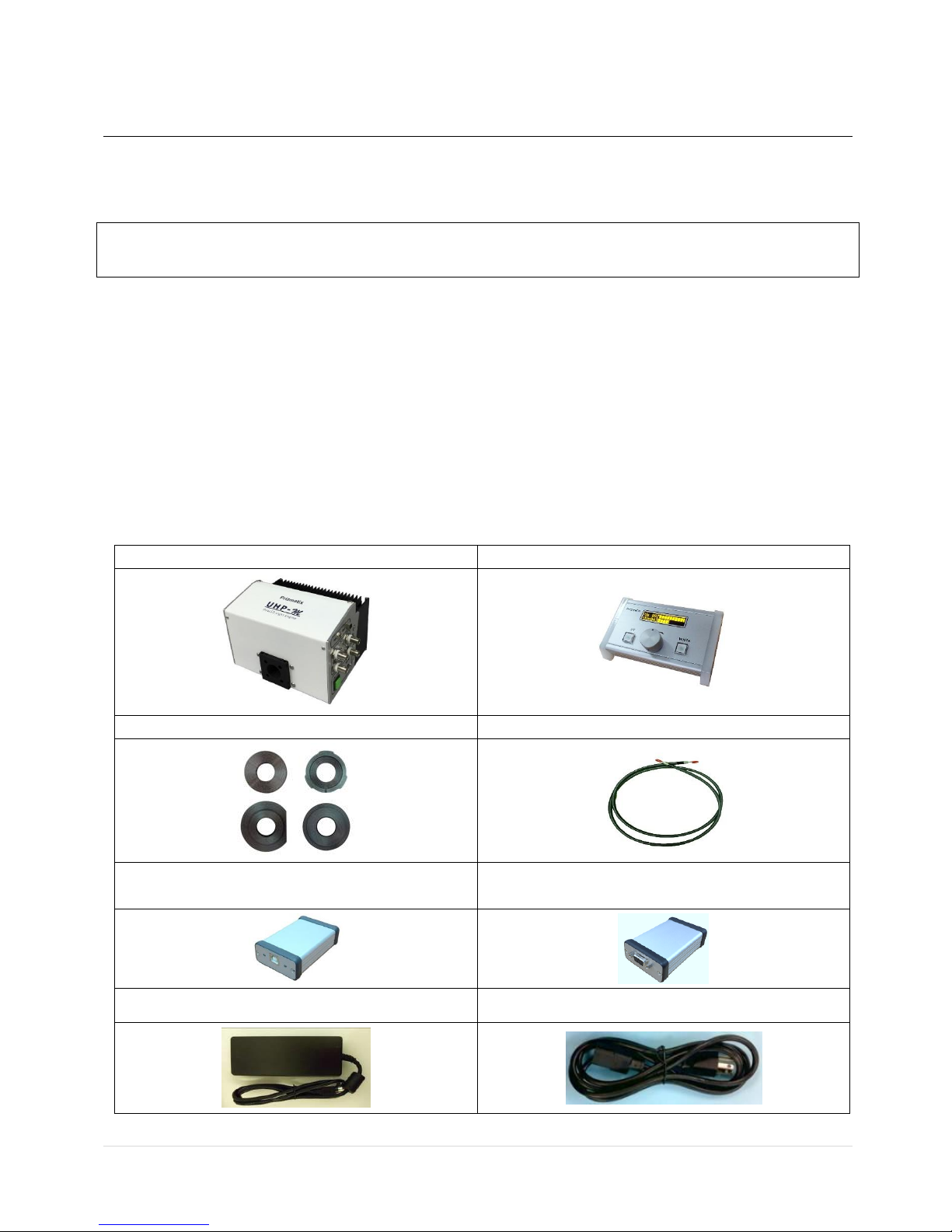
3.1 Typical package contents list
(1) UHP-M-LED Illuminator
(2) UHP-M-Console (optional item)
(3) Mic-ADPT (one of)
(4) LLG3 (optional items)
(5) UHP-M-USB Interface (optional item)
(6) UHP-M-RS232 Interface (optional item)
(7) Power Adaptor
(8) Mains Power Cord

Prizmatix
5 | P a g e UHP-M User Manual
#
Item
Description
QTY
1
UHP-M-LED
UHP-M-LED Illuminator
1
2
UHP-M-Console
Wired control console (optional item)
1
3
Mic-ADPT
Adaptor for Olympus, Nikon, Zeiss or Leica microscope
(typically only one adaptor is purchased)
1
4
LLG-3
Liquid light-guide 3 mm core (Optional item)
5
UHP-M-USB
USB to computer interface (Optional item)
6
UHP-M-RS232
RS232 to computer interface (Optional item)
7
Power Adaptor
Universal power adaptor
1
8
Mains Power Cord
Cord to connect the power adaptor to mains voltage
1
3.2 System overview:
Figure 1: UHP-M Illuminator overview: (1) Light output port, (2) Main control and connections
panel, (3) Heatsink, (4) Two lens Z-adjustment screws for UV and White (bottom, not seen in this
position).

Prizmatix
6 | P a g e UHP-M User Manual
Figure 2: UHP-M Main control and connections panel: (1) DC power jack, (2) On/Off illuminated
pushbutton, (3) Remote controller connector port, (4) Optional external fan connector jack, (5)
Visible light –TTL input, (6) Visible light –TTL enable toggle switch, (7) Visible light - Analog input
(Ain) , (8) Visible light - Analog input (Ain) enable toggle switch, (9) UV light –TTL input, (10) UV
light –TTL enable toggle switch, (11) UV light - Analog input (Ain) connector, (12) UV light - Analog
input (Ain) enable toggle switch.
Prizmatix
7 | P a g e UHP-M User Manual
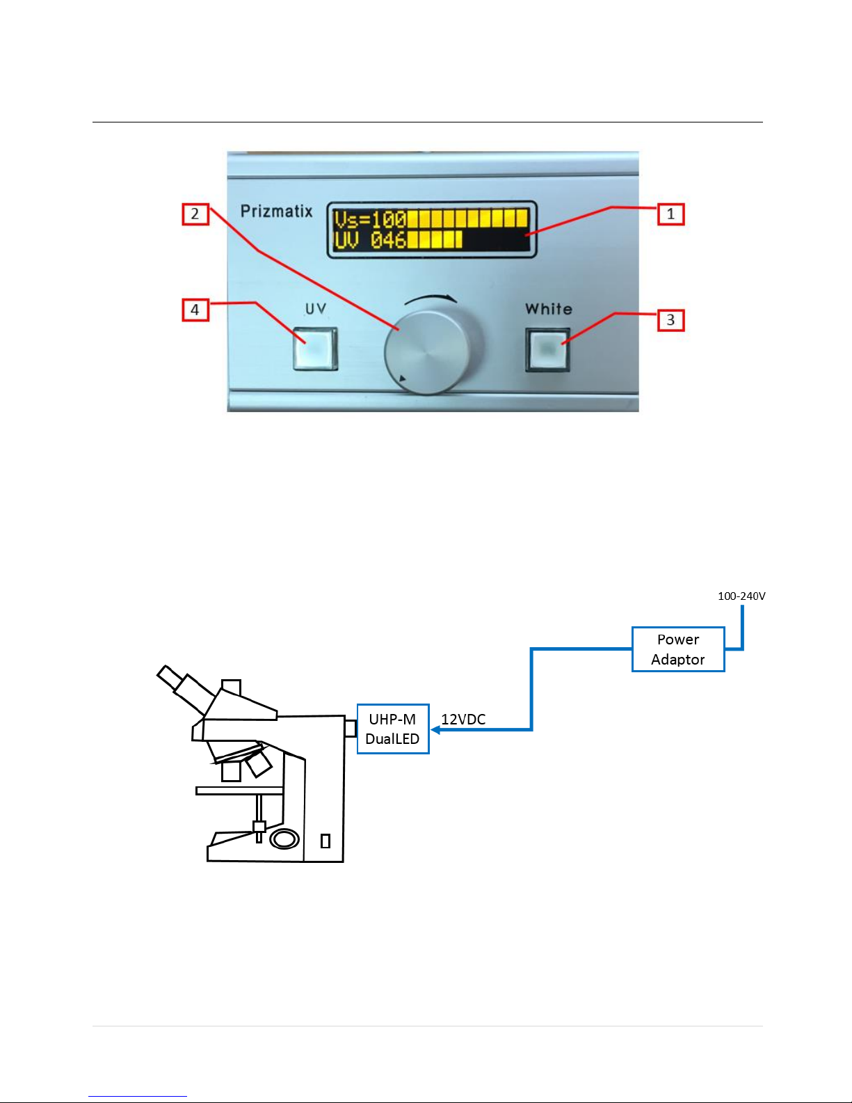
Figure 3: UHP-M-Console: (1) 2-lines display, (2) adjustment (by rotation) and selection (by
clicking) dial, (3) White (visible) light On/Off illuminated pushbutton, (4) light On/Off illuminated
pushbutton.
3.3 UHP-M illuminator system configurations
The UHP-M illuminator and its control units (Console and USB Interface) can be assembled
on microscope in several various configurations as described in following figures.
Figure 4: Basic On/Off - The most basic system comprising UHP-M head assembled on the
epi-fluorescence port of microscope and connected to the power adaptor. In this
configuration, the UHP-M mimics the standard Mercury lamp. Console control unit is not
used.

Prizmatix
8 | P a g e UHP-M User Manual
Figure 5: Simplest configuration: On/Off with optional camera sync. system comprising a
camera connected to computer. The UHP-M head assembled on the epi-fluorescence port
of microscope and connected to the power adaptor. In this configuration the UHP-M can
be used as standard Mercury lamp without synchronization with the camera, but it can be
easily synchronized with camera by connecting the camera’s Trigger Out signal t to UHP-M
TTL input. UHP-M-Console unit is not used.
Figure 6: Basic System: User controllable with optional camera sync: System comprising a
camera connected to computer. The UHP-M-Console control unit is connected to the UHP-
M head. In this configuration the UHP-M power can be manually controlled by the user.
The LED can be optionally synchronized with the camera by Trigger Out signal connected
to TTL input on UHP-M head.

Prizmatix
9 | P a g e UHP-M User Manual
Figure 7: Software and user controllable: Most advanced configuration comprising a
camera connected to computer, UHP-M-Console and UHP-M-USB (or UHP-M-RS232)
control units connected to the UHP-M head. In this configuration the UHP-M power can
be controlled either by software or manually. The LED can be optionally synchronized with
the camera by Trigger Out signal connected to TTL input on UHP-M head.
Figure 8: Software controllable: Similar to Figure 6 but the LED power can be controlled
only by software through USB and UHP-M-USB interface unit. Same configuration is
possible with UHP-M-RS232 interface unit.
Prizmatix
10 | P a g e UHP-M User Manual
3.4 Use of UHP-M LED illuminator on a microscope
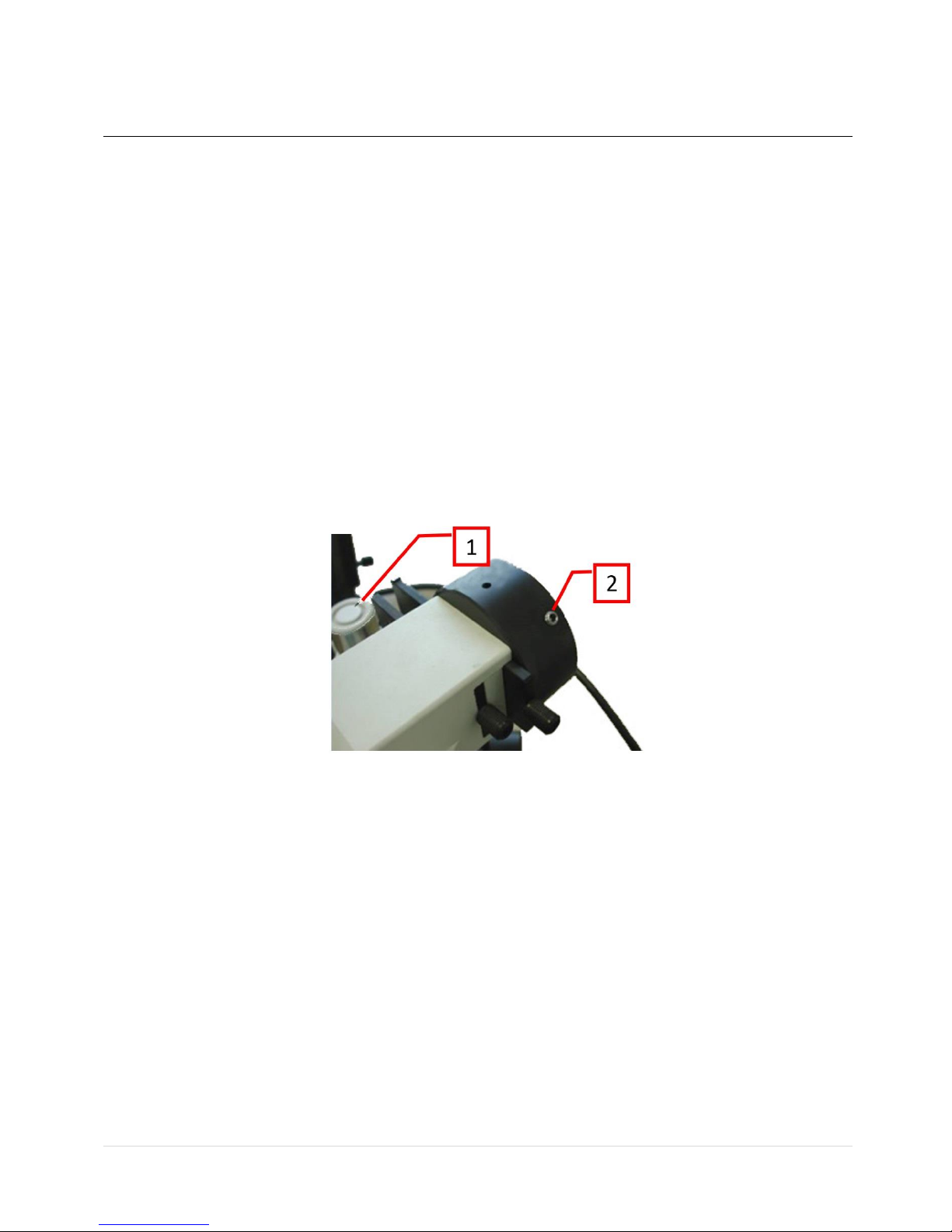
3.4.1 Setting of the illuminator LED head on the microscope
1. The UHP-M LED is designed to mount on the fluorescence lamp port (epi-fluorescence
port) of a microscope using the appropriate microscope adaptor.
2. Dismantle any existing fluorescence lamp (Hg, Xenon, etc.) from the microscope: most
microscope manufacturers (Zeiss, Olympus, Leica) use set screws to tighten the lamp onto
the port. Release the screws and carefully pull out the lamp. In the case of Nikon
microscopes with an F-mount, turn the grooved collar counterclockwise and release the
lamp.
3. Carefully insert the UHP-M-LED into the lamp port and tighten the set screws (or collar in
Nikon microscopes).
4. Observe the illumination. If needed adjust the UHP-M-LED axial focus by a Hex Key (2mm
or 5/64").
Figure 9: Olympus microscope epi-fluorescence lamp port: (1) Olympus hex screw driver, (2)
Light source fixation set screws.

Prizmatix
11 | P a g e UHP-M User Manual
3.4.2 UHP-M illuminator basic system connection
1. Check that ON/OFF green button on front panel of UHPLCC current controller is in OFF
position (Out position)
2. Ensure proper orientation and connect the UHP-M-Console cable to the Rmt port on the
UHP-M Main control and connections panel.
3. Connect the Power Adaptor cable to the 12VDC jack on the UHP-M Main control and
connections panel. Set to correct orientation and press until it clicks into place.
4. Connect the Power Cord to the Power Adaptor.
Figure 10: UHP-M LED Illuminator cable connection
5. Plug the Power cord to electrical socket (100-240V).
6. Switch the Int / Ext toggle switches at the side panel to Int position.
7. Push the green ON button. The button will light up.
8. Refer to the data displayed on the remote controller display.
CAUTION! Never disconnect the power cord form the product before switching the
ON/OFF switch button on front panel to OFF position
Prizmatix
12 | P a g e UHP-M User Manual
3.4.3 Operation of the Remote Controller
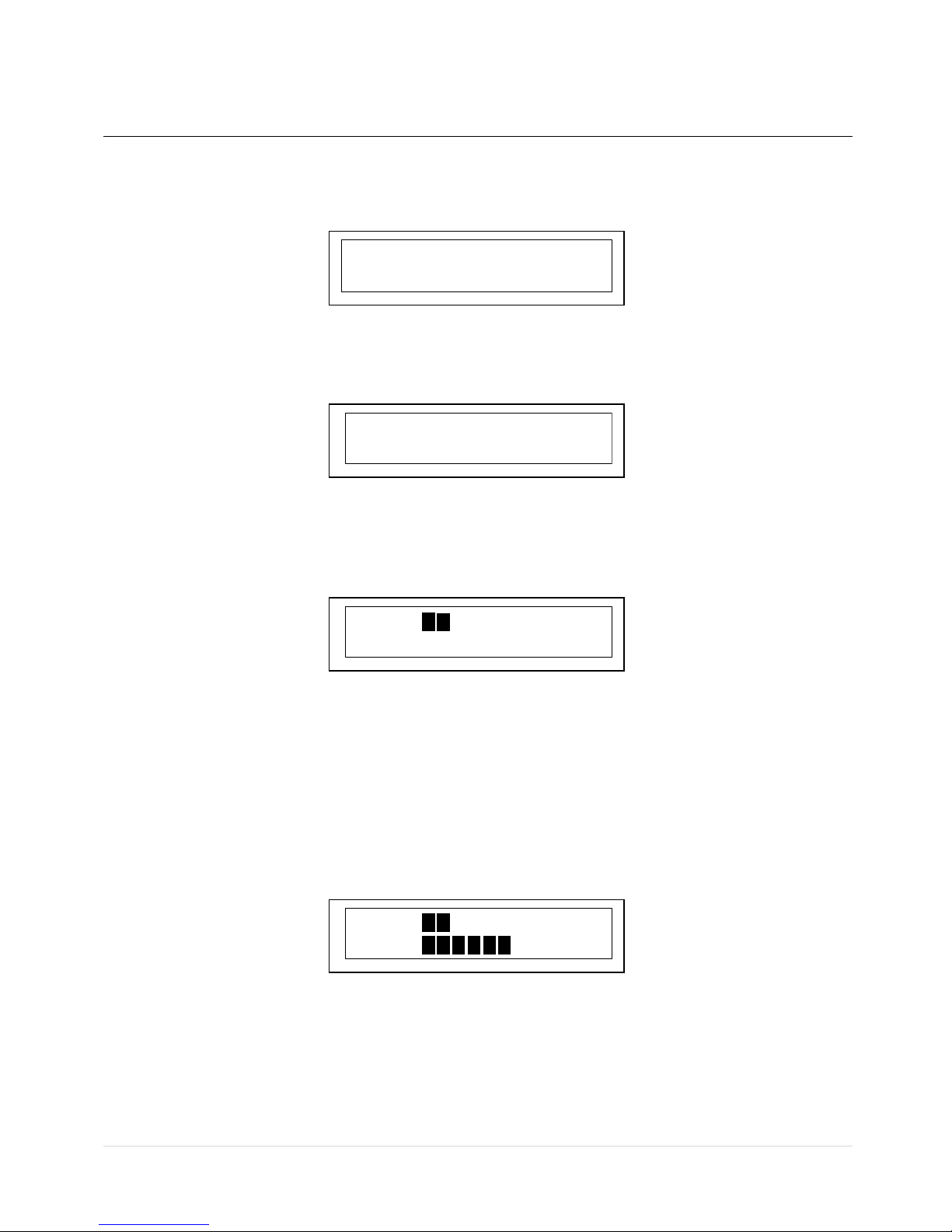
1. When the system starts up, a welcome notice is displayed for few seconds:
2. The following screen appears, indicating the illumination level of the Visible (white) LED
and the UV LED:
3. Turn the dial clockwise: the white illumination level will increase, up to 100. The numeric
display is accompanied by a graphic display - each block indicates 10% of power. The LED
will not output light yet and the pushbuttons will be off.
4. Click the WHITE pushbutton (#3 in Figure 3) to toggle the white LED On. When the LED is
On, the pushbutton itself become illuminated. The LED intensity will be as displayed on
the screen. You can adjust intensity by turning the dial clockwise or counter-clockwise.
Clicking the WHITE pushbutton again, will toggle the white LED off.
5. Clicking the dial toggles between setting the power of the White LED and the UV LED. Click
the dial –the =sign will move to the UV line. Turning the dial clockwise will now change
the UV LED power:
6. Click the UV pushbutton (#4 in Figure 3) to toggle the UV LED On. When the LED is On, the
pushbutton itself become illuminated. The LED intensity will be as displayed on the screen.
You can adjust intensity by turning the dial clockwise or counter-clockwise. Clicking the UV
pushbutton again, will toggle the UV LED off.
7. Each of these steps can be performed during the operation.
Prizmatix
UHP-M RmtCTRL
Vs=000
UV 000
Vs=020
UV 000
Vs 020
UV=060
Prizmatix
13 | P a g e UHP-M User Manual
3.4.4 Remote Controller Setup Mode
1. You can access the remote controller setup mode by pressing the dial continuously for
about 6 seconds. The following message will appear:
2. Currently, the setup mode enables adjustment of the display brightness. The following
message will appear automatically:
3. Turn the dial clockwise to increase the display brightness, and counter-clockwise to
decrease the display brightness.
4. Click the dial to set the brightness level and leave the setup mode.
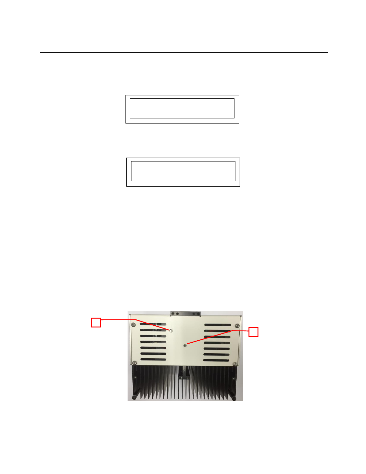
3.4.5 Illuminator alignment on the microscope
Z -alignment of the collimator lenses is required to optimize the illumination provided by the
UHP-M LED illuminator.
1. Adjustment of the Z placement of the collimating lens relative to the LED chip is done by
slightly turning the Z-Adjust screws on the bottom of the UHP-M LED head using a 2mm or
5/64" Hex Key (see Figure 6 below). Note that the span of the screw motion is less than
one full turn –this covers the full Z adjustment move.
Figure 11: Z-Axis Focus Adjust (Bottom view of the UHP-M): (1) White LED focus adjust screw, (2)
UV LED focus adjust screw.
UHP-M RmtCTRL
Setup Mode
Brightness Setup
Exit press Dial
2
1

Prizmatix
14 | P a g e UHP-M User Manual
3.4.6 Disconnection of illuminator LED head from a microscope
1. Turn the power OFF and disconnect the cables from the LED head.
2. Loosen the fixing set screws (or the F-mount collar on Nikon).
3. Pull out the UHP-M-LED head to disengage it from the microscope.
3.4.7 LED Control by TTL and / or Analog Input
The TTL input (TTL) and Analog Input (Ain) BNC connectors are located on the side panel of the
UHP-M, featuring the TTL and Ain connector and toggle switches as shown in figure 2.
To control the LED by TTL input:
•Connect the BNC cable to the TTL input and to TTL trigger source.
•Switch the "TTL Enable" toggle switch to Ext position to enable the triggering
•When TTL Enable switch is set to Ext the UHP-M-Console and / or UHP-M-USB or UHP-M-
RS232 controllers are overridden. The controllers still enable power control and LED OFF
functionality, but LED ON state will be executed ONLY when both controller and TTL are at
HIGH state –enabling fast triggering from TTL input. In case none of controllers is connected
and the “TTL Enable" toggle switch is in Ext position, TTL input state will responsible for the
LED state ON or OFF.
•While TTL input triggering, the Analog input BNC can be used for control pulse height by 0-5
Volt, see below.
To control the LED power via Analog Input voltage:
•Connect the BNC cable to the Ain input and to 0-5 Volt voltage source.
•Switch the "Ain Enable" toggle to Ext position to enable power control by analog voltage
•When “Ain Enable” switch is set to Ext the UHP-M-Console and / or UHP-M-USB or UHP-M-
RS232 controllers are overridden. The controllers will not enable power control and LED ON
/ OFF functionality.
•While Ain control, the TTL input can be used for fast pulsin.
CAUTION!:
•The absolute maximum voltage to be applied to Ain is +5V.
•The internal pin of BNC connector is Positive (+).
•The external part of the connector is Negative (-).
•The Ain input is not opto-isolated.
•The Ain is intended for LED power control via Digital to Analog (D/A) modules. It
is not suited for analog modulation of LED power at rates higher than few 10Hz

Prizmatix
15 | P a g e UHP-M User Manual
CAUTION!:
Using more than the maximum voltage or inverse polarity may cause permanent damage
to LED and Current Controller!
4 Cleaning
Keep the UHP-M LED illuminator head clear from dirt and do not leave it open. Make sure to close
the output aperture of the illuminator with a cap when it is not in use.
The UHP-M remote controller box can be wiped with mild wet-wipes.
CAUTION!:
Do not attempt to use chemicals, e.g. Alcohol or Acetone –you may damage plastic
components!
5 Specifications
5.1 Electrical specifications
TTL Input
Optically isolated BNC connectors
Analog power control
%
0-100
ON/OFF
Power switch or by TTL signal
Current controller input supply voltage
V
12
Power Adaptor Input
85-264 VAC, 47-63 Hz, 1.5 A
5.2 General specifications
Operation temperature range
°C
10 - 35
Storage temperature range
°C
-10 - 55
Operating relative humidity (Non condensing)
%
<90
Head dimensions
See drawing below
Head weight
g
2600
Controller dimensions (L x W x H)
mm
185 x 124 x 153
Controller weight
g
280
Power adaptor dimensions (L x W x H)
mm
175 x 72 x 35
Power adaptor weight
g
650
Power Adaptor Safety

Prizmatix
16 | P a g e UHP-M User Manual
UHP-M main body
UHP-M-Console (left) and UHP-M-USB (right) control units (UHP-M-RS232 has same dimensions)
Table of contents
Other Prizmatix Laboratory Equipment manuals


Popular Laboratory Equipment manuals by other brands

usi
usi KK 6610TP installation manual

Hettich
Hettich ROTIXA 500 RS operating manual

Selecta
Selecta MICRO 8 manual

NuAire
NuAire NuWind NU-C200V Operation & maintenance manual

Hitachi
Hitachi ChromasterUltra Rs 6270 instruction manual

Planet Networking & Communication
Planet Networking & Communication POE-164 user manual


