Prizmatix Optogenetics-LED User manual

Prizmatix
Main Office
Phone: +972-27-2500097
sales@prizmatix.com
European Sales Office
Phone: +44 (0) 77-9172-9592
sales.europe@prizmatix.com
North America Sales Office
Phone:+1 - (248) - 436-8085
sales.usa@prizmatix.com
Azrieli C enter, Ho lon, Israel
USER MANUAL
Optogenetics-LED
Fiber Coupled LED for
in-vivo
Optogenetics Experiments with Freely Moving Mammals
Version: 7

Prizmatix
2 | P a g e Optogenetics-LED User Manual
Contents
1 Introduction ................................................................................................................ 3
1.1 Features................................................................................................................ 3
1.2 Intended Use........................................................................................................ 3
2 Safety .......................................................................................................................... 3
2.1 Eye Safety............................................................................................................. 4
2.1.1 Special Safety Notes...................................................................................... 4
2.1.2 Hazard Distances (HD) .................................................................................. 5
3 Set-up of the Device.................................................................................................... 5
3.1 Package Contents List........................................................................................... 5
3.2 Specifications........................................................................................................ 6
3.2.1 Electrical Specifications................................................................................. 6
3.2.2 General Specifications .................................................................................. 6
3.3 System Overview.................................................................................................. 7
3.3.1 Optogenetics-LED Controls........................................................................... 7
3.3.2 Typical System Setup .................................................................................... 8
3.4 Initial Set-up of Optogenetics-LED ....................................................................... 8
3.5 Cleaning................................................................................................................ 9

Prizmatix
3 | P a g e Optogenetics-LED User Manual
1 Introduction
The Prizmatix Optogenetics-LED module is specially designed to provide high power Light
to activate opsins in Optogenetics experiments with freely moving mammals. This LED
light-source provides powerful light pulses triggered by external TTL input.
1.1 Features
•High Power
•Reciprocal SMA fiber connection
•Precisely adjustable power by 10 turns potentiometer
•TTL external modulation input (up to 50KHz)
•Analog input (0-5V) for power control
•TTL and Analog Inputs are Optically Isolated
1.2 Intended Use
The Optogenetics-LED is an in-vivo illuminator designed to be used with free-moving small
animals inside maze systems. The unit is self-contained. The LED light exits through an
SMA ferrule directly to an attached 1000um POF, which is connected to a rotary joint. On
the other side of the rotary joint is a 500um POF which shall be connected to the
implanted cannula in the animal.
2 Safety
Please make yourself familiar with the contents of these operating instructions before
using the Optogenetics-LED system. Use the illuminator only as specified in this manual.
Otherwise, the protection provided by the illuminator may be impaired.
The following symbols are used for the warnings:
CAUTION! Failure to comply with the safety instructions can be hazardous to
the user.
CAUTION! Failure to comply with the safety instructions can result in
damage to the instrument.
Do not use the illuminator if it is damaged. Before you use the illuminator, inspect the
case. Look for cracks or missing parts.
Do not use the device around explosive gas.
Never operate the illuminator with the cover removed or the case open.
Any maintenance should ONLY be performed by a Prizmatix authorized technician.

Prizmatix
4 | P a g e Optogenetics-LED User Manual
Prizmatix products are NOT authorized for use as components in life support devices or
systems.
2.1 Eye Safety
The Optogenetics-LED illuminator is assigned to following risk groups according to IEC
62471: 2006. The assignment done based on the standard system configuration as
explained in section 3.3.2. The assignment results are summarized in Table 1.
Table 1: Optogenetics-LED illuminator assignment to risk groups according to IEC 62471:
2006.
Product Type
Assignment to Risk Group
Exempt
RG0
Low Risk
RG1
Mod Risk
RG2
Optogenetics-LED-Violet
Optogenetics-LED-Blue
Optogenetics-LED-Green
Optogenetics-LED-Red
The products Optogenetics-LED-Violet and Optogenetics-LED-Blue are marked on the
product with following label:
Risk Group 2
CAUTION Possibly hazardous optical
radiation emitted from this product
2.1.1 Special Safety Notes
Table 2 summarize the safety notes specific to various product types (IEC 62471-2/TR
(1st edition, 2009), Table 2 page 17).
Table 2: Safety notes specific to various product types
Product
Safety Note
Optogenetics-LED-Violet
CAUTION! Do not stare at operating lamp.
May be harmful to the eyes
Optogenetics-LED-Blue
CAUTION! Do not stare at operating lamp.
May be harmful to the eyes
Prizmatix
5 | P a g e Optogenetics-LED User Manual
2.1.2 Hazard Distances (HD)
Following Table 3 provides the distance from distal end of the fiber at which the threshold
illuminance EL returns the product to RG 1.
Table 3: Distances from distal end of the fiber at which the photochemical hazard
reduces to Risk group 1, for relevant products.
Product
Distance at which Blue-Light hazard reduced to Risk Group 1
[m]
Optogenetics-LED-Violet
0.35
Optogenetics-LED-Blue
0.4
3 Set-up of the Device
Remove the device from the packaging and inspect the device for loose components or
any signs of damage. Notify Prizmatix if the device appears damaged in any way: do not
install or operate a damaged device.
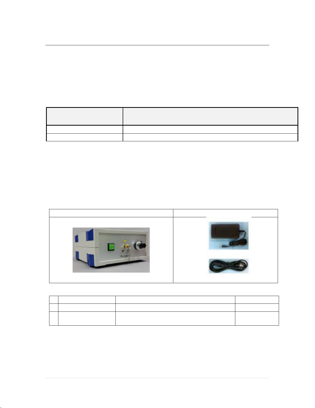
3.1 Package Contents List
Optogenetics-LED
Power Adaptor / Mains Power Cord
Item
Description
Quantity
1
Optogenetics-LED
High Power LED light source
1
2
Power Adaptor /
Mains Power Cord
Universal power adaptor and Cord to connect
the power adaptor to mains power
1

Prizmatix
6 | P a g e Optogenetics-LED User Manual
3.2 Specifications
3.2.1 Electrical Specifications
Digital modulation inputs
Optically isolated TTL
Connector for TTL and Analog input
BNC
Digital modulation frequency
Hz
DC-30000
Rise / Fall time (10% - 90%)
µs
<3 / <10
Analog input voltage range
V
0-5
Input Voltage
V
12
Max Input current
A
5
Power Adaptor Input
85-264 VAC, 47-63Hz, 1.5A
3.2.2 General Specifications
Operation temperature range
°C
10 - 35
Storage temperature range
°C
-10 - 55
Operating relative humidity (Non-condensing)
%
<90
Dimensions (L x W x H)
mm
197 x 174 x 80
Weight
g
750
Power adaptor dimensions (L x W x H)
mm
125 x 50 x 31.5
Power adaptor weight
g
300
Power Adaptor Safety
Fan noise
dBA
28.4
Prizmatix
7 | P a g e Optogenetics-LED User Manual
3.3 System Overview
3.3.1 Optogenetics-LED Controls
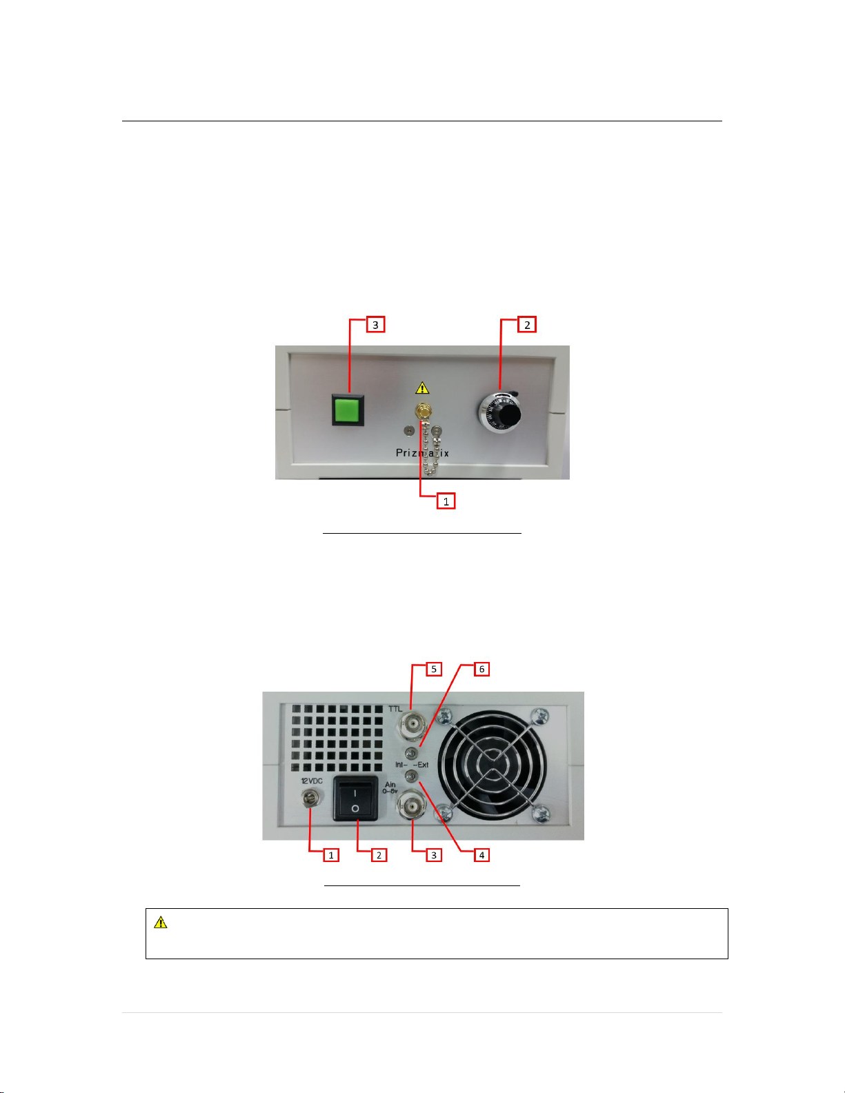
The front panel of Optogenetics-LED unit features: (1) SMA connector for optical fiber, (2)
10 turn dial of precision potentiometer for manual setup of output power, (3) LED Enable
(ON/OFF) switch.
Optogenetics-LED front panel
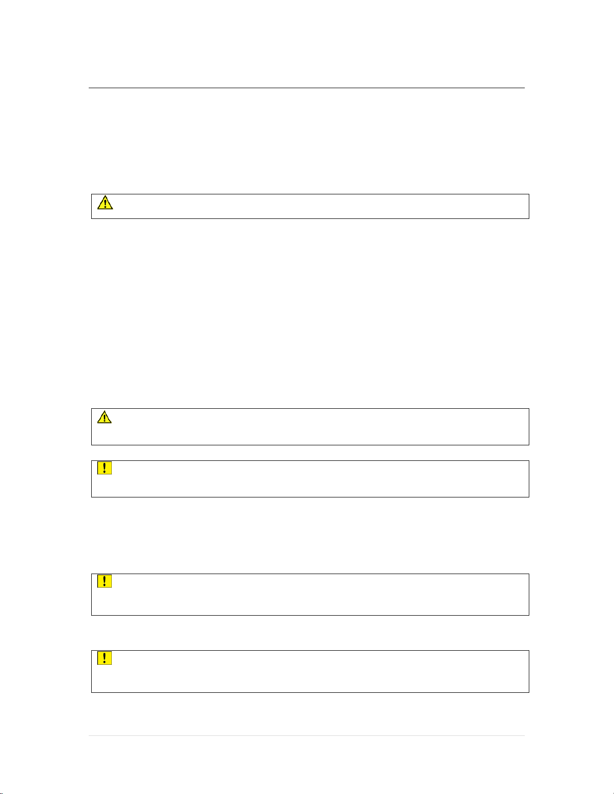
The back panel of Optogenetics-LED unit features: (1) Power adaptor input socket, (2)
Main power switch, (3) Connector for Analog input (0-5V) for control of LED power from
computer, (4) Toggle switch Analog Input Int/Ext to enable control of LED power by
external analog input, (5) Connector for TTL input, (6) Toggle switch TTL Input Int/Ext to
enable control of LED ON/OFF by external TTL signal
Optogenetics-LED back panel
CAUTION!: Do not use the illuminator without the Optical Fiber
connected to SMA port!

Prizmatix
8 | P a g e Optogenetics-LED User Manual
3.3.2 Typical System Setup
Typical Optogenetics setup will include following components:
(1) Optogenetics-LED - Fiber coupled LED light source
(2) Optogenetics-Fiber-1000 - Polymer optical fiber 1000um core, NA 0.63, length
1m, optical connectors SMA-FC
(3) Rotary Joint - Enables free movement of the mammals
(4) Optogenetics-Fiber-500 / Optogenetics-Fiber-Dual-500 - Single or Dual branch (Y-
shape) polymer optical fiber 500um core, NA 0.63, optical connectors FC-ferrule
(5) Cannulae - One or two fiber optic implant shall be connected to 500um fiber by
a sleeve
(6) Pulser - Pulse generator to provide fast TTL pulses to the LED
3.4 Initial Set-up of Optogenetics-LED
1. Set Power Switch on back panel of the unit to OFF position and connect power
adaptor to the back of the unit and into wall mains socket.
2. Set both the TTL and Ain (Analog Input) switches on back panel to ‘Int’position.
3. Connect the Optogenetics-Fiber-1000 fiber to the front panel SMA connector.
4. Connect the other end of the Optogenetics-Fiber-1000 fiber to the Rotary-Joint.
5. Connect the FC connector on the 500um fiber to the Rotary-joint.
Prizmatix
9 | P a g e Optogenetics-LED User Manual
6. Push the back-panel power switch to the "ON" position, and then Press the green
button on front panel to turn the LED on (the internal green light of the button is
turned on too). Turn the dial of the potentiometer clockwise. The LED light should
be seen at the ferrule on the 500um fiber.
CAUTION!: Do not stare at operating lamp. May be harmful to the eyes
7. LED power can be adjusted using the 10-turn potentiometer on front panel.
8. Press the green button once again, the LED is turned off (as indicated by the button
light). Make sure to turn the unit off by switching the Power Switch on back panel
before disconnecting from power supply.
9. For TTL input connect BNC cable to TTL input connector on back of unit. To enable
TTL control change the position of the TTL Int/Ext switch to Ext position.
10. For Analog Input connect BNC cable to Ain input connector on back of unit. To
enable Analog Input control change the position of the Ain Int/Ext switch to Ext
position
CAUTION!: Do not use the illuminator without the Optical Fiber
connected to SMA port!
CAUTION!: Do not cover back panel of unit - ensure that air can circulate
freely.
3.5 Cleaning
Keep the connector port clear from dirt and do not leave it open. Make sure to close the
SMA port with the chained cap when the fiber is not connected.
CAUTION!: Do not try to clean inside the port –you may damage the
illuminator!
The box can be wiped with mild wet-wipes.
CAUTION!: Do not attempt to use chemicals, e.g. Alcohol or Acetone –
you may damage plastic components
This manual suits for next models
4
Table of contents
Other Prizmatix Laboratory Equipment manuals


Popular Laboratory Equipment manuals by other brands


Hygiena
Hygiena Dualo 32 R2 Product instructions

Hitachi
Hitachi CR22N instruction manual

Datalogic
Datalogic Heron HD3430 Product reference guide

TORREY PINES SCIENTIFIC
TORREY PINES SCIENTIFIC EchoTherm IC22 operating manual

Bibby Sterilin
Bibby Sterilin Techne TC-512 Operator's manual

Prestige medical
Prestige medical Anima user manual