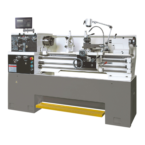
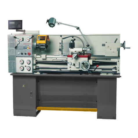
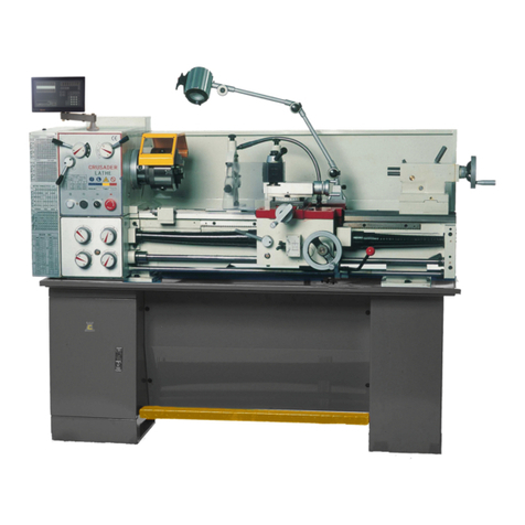
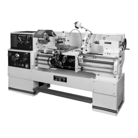
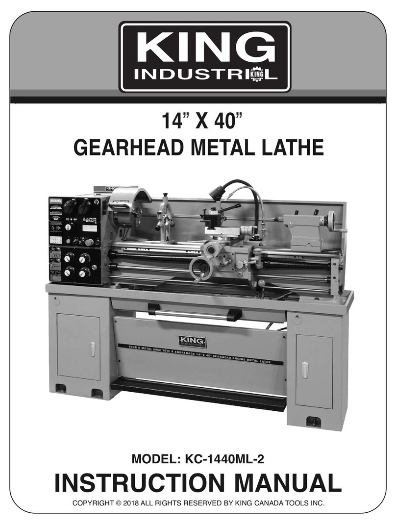
CHESTER DB8VS User manual

DB8VS
LATHE
Manual
Chester UK Lt
d
Clwyd Close
Hawarden Industrial Par
k
Hawarden
Chester CH5
3PZ
Tel: 01244
531631
sales@chesterma
ch
i
n
etools.com
www.
ch
esterma
ch
i
n
etools.com

Safety guidelines
Personnel working with any machine tools are required to follow the safety instructions stated below in order to
prevent any accident that may occur.
• Appropriate personal protective equipment (such as safety glasses, dust coat, shoes etc..) must be worn
whilst operating the machine.
• Long hair or ties must be tightened up.
• Hand gloves should never be used.
• Workpieces and cutting tools must be properly clamped.
• Chuck keys must be removed when not in use.
• Do not leave any loosened parts on the machine table.
• Ensure you know how to operate the machine before switching on.
• Machine guards must be put in position when in use.
• Keep hands away from any rotating objects.
• Cutters used should be correctly ground and in good condition.
• Use the correct cutting speed, feed rate, and depth of cut from time to time.
• Spilled oil or cutting fluid must be swiped off immediately.
• Never use a hand file or emery cloth for finishing lathe work pieces.
• Do not leave a running machine unattended.

Index
1. Machine Markings ………………………………………………………………………………………………… 4
2. Proper Use ………………………………………………………………………………………………………… 4
3. Technical Data …………………………………………………………………………………………………….. 4
4. Safety Indications …………………………………………………………………………………………………. 5
4.1 Residual Risk …………………………………………………………………………………………………. 5
5. Transport of the Machine ………………………………………………………………………………………… 6
6. Unpacking and Cleaning …………………………………………………………………………………………. 6
6.1 Cleaning the Machine ……………………………………………………………………………………….. 6
7. Extent of supply and accessories ……………………………………………………………………………….. 7
7.1 Extras ………………………………………………………………………………………………………….. 7
8. Installing the Machine ……………………………………………………………………………………………. 8
8.1 Using a substructure ………………………………………………………………………………………… 8
8.1.1 Using the Machine with the Substructure ………………………………….……………………. 8
8.1.2 Installation Drawing ………………………………………………………………………………… 9
9. Power Connection ……………………………………………………………………………………………….. 10
9.1 Lathes with Frequency Connector …………………………………………………………………….……10
10. Control Elements ……………………………………………………………………………………………….... 11
11. Design of the Lathe ……………………………………………………………………………………………… 12
11.1 Lathe Bed …………………………………………………………………………………………………... 12
11.2 Headstock ………………………………………………………………………………………………….. 12
11.3 Lathe Saddle ………………………………………………………………………………………………. 12
11.4 Tailstock ……………………………………………………………………………………………………. 12
12. Operation of the Lathe …………………………………………………………………………………………. 13
12.1 Lathe saddle with cross and top slide ………………………………………………………………….. .13
12.1.2 Turning tapers with the cross slide …………………………………………………………….... 13
12.2 Tailstock ……………………………………………………………………………………………………. 13
12.3 Speed and Feed …………………………………………………………………………………………... 14
12.3.1 Arrangement of belt drive and feed gear ……………………………………………………….. 14
12.3.2 Adjusting the speed ……………………………………………………………………………….. 14
12.3.3 Adjusting the feed ………………………………………………………………………………..... 15
12.3.4 Pitches for thread-cutting ………………………………………………………………………..... 15
13. Adjustments on the lathe ………………………………………………………………………………………. 16
13.1 Guide rail with adjusting gib on the lathe saddle …………………………………………………. 16
13.2 Tapered gib on the cross slide ……………………………………………………………………… 16
13.3 Tapered gib on the top slide ………………………………………………………………………... 16
13.4 Adjusting the tapered gib for the leadscrew nut ………………………………………………….. 16
13.5 Adjusting the lathe chuck guard ……………………………………………………………………. 17
13.6 Replacing the clamping devices on the head spindle holding fixture …………………………... 17
13.7 Fitting the follow rest (optional) ………………………………………………………………………17
14. Working notes and tools………………………………………………………………………………………… 18
14.1 Turning operations ……………………………………………………………………………………. 18
14.1.1 Straight turning ………………………………………………………………………………… 18
14.1.2 Facing and recesses ………………………………………………………………………….. 18
14.1.3 Turning between centres ……………………………………………………………………… 18
14.1.4 Turning short tapers with the top slides ……………………………………………………… 19
14.1.5 Thread-cutting (example of male thread) ……………………………………………………. 19
14.2 Cutting tool types and indications ……………………………………………………………………. 19
14.3 Bits and countersinks ………………………………………………………………………………….. 20
15. Maintenance ……………………………………………………………………………………………………… 21
15.1 Machine care ………………………………………………………………………………………….. 21
15.2 Lubrication……………………………………………………………………………………………… 21
15.3 Maintenance …………………………………………………………………………………………… 21
16. Warranty …………………………………………………………………………………………………………... 21
17. Troubleshooting ………………………………………………………………………………………………….. 22
18. Wiring diagram …………………………………………………………………………………………………… 23
19. Exploded views and spare parts list ……………………………………………………………………………. 24

1. Machine Markings
This machine bears a characteristics plate with the name of the machine, item number, and key technical data. Keep it
clean and legible at all times.
2. Proper Use
This lathe has been designed and manufactured for straight turning and facing round or regularly-formed three, six or
twelve square workpieces in metal, plastic, or similar materials. The leadscrew also enables thread cutting.
Do not use this machine for materials that constitute a heath hazard or create dust, such as wood, Teflon, etc..
Follow the indications of this manual, as well as the information labels on the lathe. This machine is suitable for use in
schools, industrial workshops, and for d.i.y work.
Note:
Any unauthorised modifications to this machine, improper use or disregard for the safety standards, will
exempt the manufacturer from any liability for resulting harm to persons or objects and shall result in the
invalidity of claims under the guarantee.
3. Technical Data
Max. Swing over bed
210mm
Distance between centres
400mm
Max. Swing over cross-slide
110mm
Centre height
105mm
Width of bed
135mm
Toolpost tool size
10mm
Speed range
50-2500rpm
Cross-slide travel
110mm
Chuck diameter
100mm
Spindle bore
21mm
Spindle taper
MT3
Tailstock quill travel
70mm
Tailstock taper
MT2
Metric threads can be cut
0.403mm
Inch threads can be cut
10-44TPI
Motor power
750W (1hp)
Net weight
110kg
Dimensions
1050 x 560 x 570mm

4. Safety Indicators
Read the operating and maintenance instructions carefully before starting, using or performing maintenance work on
the machine, and prior to any other operations. Only authorised personnel who are completely familiar with the
machines handling and working principles are authorised to use it.
Repair, maintenance and upgrading may only be carried out by technical personnel and when the machine is switched
off.
• Check that the workpiece is properly positioned before starting
• Never place your hands close to rotating parts when working with the machine
• Do not remove sharp edged chips by hand, use a hand brush or chip hook
• Use the protection devices and attach them firmly. Never work without protection devices; keep them in
proper working condition. Check that they are operational before starting any work
• Keep the machine and it’s working environment clean at all times. Use sufficient lighting when working
• Secure workpieces with adequate clamping devices when working. Provide an adequate supporting surface
• Do not alter the machine. Do not use for any purposes other than those directed by the manufacturer
• Do not work on the machine if your concentration is reduced as a result of illness, fatigue, drugs, alcohol, or
medication
• Remove keys and other loose parts after assembling or repairing the machine, and before starting it
• All safety and warning labels on the machine must be observed and kept intact and legible
• Keep children and any persons unfamiliar with the machine away from the work area ,machine, and any tools
• The machine may only be used, set up and maintained by persons familiar with and instructed in the relevant
dangers
• During maintenance, commission, and repair, always switch off the machine. Disconnect the plug from the
power supply
• To remove the plug from the power outlet, do not pull the cord. Protect the cord from heat, oil, and sharp
edges
• Ensure that the main switch is in the off position when connecting the machine to the mains in order to
prevent accidental start up
• Wear a well-fitting work suit, goggles, safety shoes and ear protection. Tie long hair back. Do not wear
watches, bracelets, necklaces, rings, or gloves whilst working
• Immediately element any anomalies which may affect safety
• Never leave the machine unattended when running. Stay by it until the tool has come to a complete stop. Pull
the plug to prevent the machine from being switched on accidentally
• Keep the machine dry
• Never use electrical tools and machines near flammable liquids and gases
• Before using the machine, ensure that no components are damaged. Damaged components must be
replaced immediately in order to prevent possible danger
• Do not overload the machine. It is better and safer to work within the indicated performance range. Use the
correct tool, and ensure that they are not blunt or damaged
• To prevent risk of danger and accidents, only use the original spare parts and accessories for your machine
4.1 Residual risk
Even when all safety standards are observed, and the machine is used properly, there still remains some residual risk,
such as:
• Touching rotating pieces or tools
• Breakage of tools
• Damage as a result of components or parts of components flying off at high speed
• Fire hazard in case of insufficient ventilation of the motor
• Contact with live parts
• Damage to hearing when working for long periods without ear protection
All machines involve some residual risk. Any operations should be performed with due care.

5. Transport of the machine
This machine would normally be delivered in a special transport case. Keep it and reuse it.
All bright metal parts are lubricated to protect them from humidity and dirt.
Do not stack the machine. To prevent damage, do not deposit objects on the machine during transportation and
storage.
Protect the machine from moisture and rain. Keep electrical equipment dry.
Take the weight into account when transporting and installing the machine. Make sure that the means of transport and
the base on which the machine will be deposited can bear the load.
6.Unpacking and cleaning
The machine comes pre-assembled. Please check the machine immediately after receiving for any damage incurred
during transportation. If you spot any damage, immediately inform the transport operator and authorised dealer.
6.1 Cleaning the machine
Before transportation, all bright parts of the machine are thoroughly greased with protective wax and grease to avoid
corrosion.
Before commissioning, clean the machine with a suitable environmental-friendly cleaning agent (such as stove
distillate). Do not use any solvents, thinners, or other cleaning agents which might corrode the varnish on the
machine.
Follow the specifications and instructions of the manufacturer of the cleaning agent. Ventilate the area well when
cleaning in order to avoid any health hazards due to fumes.
Once the machine has been cleaned, all bright metal parts must be lightly lubricated. Use a non-corrosive lubricating
oil for this purpose.
Warning: Many cleaning agents are combustible and are highly flammable. Do not smoke when handling cleaning
agents.
Note: Oil, grease, and cleaning agents are pollutants and must be disposed of carefully. Dispose of these agents in
accordance with current legal requirements. Cleaning rags impregnated with oil, grease, and cleaning agents are
flammable. Dispose of these carefully.

7. Extent of supply and accessories
Included with your machine:
• Lathe
• 3 and 4 jaw chucks
• Lathe tools
• Centres
• Chuck guard
• Operating manual
7.1 Extras
We recommend the following for use with this machine:
• Chip tray
• Stand
• 125mm 4 jaw chuck
• Steady rest
• Follow rest
• Face plate
• 10mm lathe tool set
• 12mm lathe tool set
• Collet chuck holder
• 3-16mm collet chuck set

8. Installing the machine
When choosing the workpiece, bear the following points in mind:
• The device must be installed and operated in a dry and well-ventilated area
• Avoid locations near chip or dust generating machines
• Place in a vibration free area, at a distance from stamping machines, planing machines, etc..
• Use a suitable base (bearing capacity and evenness of the floor). Compensate possible unevenness with
suitable padding
• Leave sufficient space for the user
• Provide sufficient lighting
• Ensure a current supply
Ensure that no unauthorised personnel or children are in the danger area of the machine during operation.
The machine base must be conditioned so that no split oil or coolant can penetrate the floor.
8.1.1 Using a substructure
Ensure that the substructure is placed on even ground and that the machine is levelled exactly with a spirit level. If
not, there is danger that the lathe bed may become warped, making the machine unusable.
Attach the machine firmly to the substructure.
8.1.2 Using the machine with the substructure
When using an existing worktable or bench, also check the evenness of the installation surface. Use a spirit level for
levelling, ensure that the machine is firmly attached to the substructure. Only use a base suitable for the machine.
We do not recommend using unattached machines, as this will move during operation.

8.1.3 Installation drawings

9. Power Connection
Note: Connection of the lathe and all other electrical work may only be carried out by an authorised electrician
Before connecting the machine to the mains, make sure that the electrical values of the mains supply are the same as
those for the lathe’s electrical components. Use the wiring diagram for connecting the lathe to the mains supply.
We recommend that you connect the machine separately to other power consuming appliances, using a fused and
lockable connection.
If the turning direction is not correct, change the phase connection order at the terminal or plug.

10. Control Elements
Please be aware that the machine should only be run at low revs and high loads for a limited amount of time, and then
run unloaded at full speed to allow the motor to cool.

11. Design of the lathe
Bear the following points in mind to ensure that you get the best results from your work.
Rotating parts.
• Start work carefully
• Pay close attention to your work, and pay special attention to rotating parts
• Wear a well fitting work suit
• Make sure that your hair or clothes do not get caught in any moving parts
• Wear a hairnet
• Do not wear jewellery when working with the machine
When using the machine, chips and parts may fly off at high speed. It is essential to wear work goggles to protect your
eyes from chips and other parts that may fly off at speed.
Before starting any work, check the following points:
• Check that cables, connections, etc.. are not damaged
• Only use sharp tools
• Check that the work piece and tool are firmly clamped
• Note that you need different speeds for different materials and operations
• Check the feed speed
• Lubricate regularly as indicated in the maintenance section
11.1 Lathe Bed
The lathe bed needs to be rigid and vibration free. This is cast in one single
piece provided with strong stiffening ribs.
The lathe bed integrates the headstock and drive unit, for attaching the
lathe saddle and leadscrew, and for guiding the lathe saddle and tailstock.
11.2 Headstock
The headstock houses the work spindle with bearing arrangement and the
drive unit.
The work spindle transmits the main movement during the turning process.
It also holds the workpieces and clamping devices (e.g jaw chuck).
The work spindle is driven by an electromotor via pulleys.
11.3 Lathe saddle
The lathe saddle contains the control elements for the different feeds and
supports the apron.
The following functions are carried out:
• Manual feed via handwheel of lathe saddle
• Movement of the cross slide via handwheel
• Automatic longitudinal feed via the leadscrew
• Threading with the leadscrew
11.4 Tailstock
The tailstock is used for centring and drilling, supporting long shafts, and
turning centres, as well as turning long, thin tapers.

12. Operation of the lathe
12.1 Lathe saddle with top and cross slide
The automatic longitudinal feed and the feed for thread-cutting are
activated and deactivated using the feed lever.
1. The feed is transmitted via the leadscrew nut. Push the feed lever
down to engage the automatic longitudinal feed.
2. The handwheel is used to manually traverse the lathe saddle.
3. The cross slide is moved forward and backward manually with the
handwheel.
4. The top slide bears the quadruple toolholder (5) and is therefore
also known as the tool slide. Use the handwheel (6) to move the
top slide.
12.1.1 Turning tapers with the top slide
It is also possible to turn short tapers with the top slide. To do this loosen the two nuts (7) to the left and the right of
the top slide. You can then rotate the top slide.
After setting the required position, retighten the top slide.
12.2 Tailstock
1. The tailstock sleeve is using to hold the tools (bits, lathe centres,
etc..). The spindle sleeve has a millimeter scale.
2. The spindle sleeve is clamped using the clamping lever.
3. The spindle sleeve is extended and retracted with the handwheel.
4. The tailstock on the lathe bed can be clamped with the locking
nut.
5. The adjusting screws to the left and right of the tailstock are used
to “de-centre” the tailstock to turn long, thin tapers. The locking
nut (4) must be loosened for this purpose.
“De-centering” the tailstock:
Check that the tailstock is loosened.
1. Unscrew the locking screw at the rear side approx ½ turn.
2. Move the tailstock out of its centered position by alternately
loosening and tightening the two adjusting screws.
3. The desired cross-adjustment can be read off the scale.
4. First retighten the rear locking screw and then the two adjusting
screws. Retighten the tailstock tailstock with the locking nut.
In order to avoid accidental extraction of the tailstock out of the lathe bed,
a securing screw (1) has been fitted at the end of the lathe bed.
Check clamping of the tailstock and the sleeve, respectively, for turning
jobs between centres.

12.3 Speed and feed
The characteristics plate is attached to the headstock. It shows also shows
the speed table (1).
The feed table is attached to the belt cover. It shows the feeds for straight
turning (2), the change gear arrangement (3) for longitudinal feed and for
thread-cutting, change gear table for metric threads (4) and for imperial
threads (5).
In order to change the speed or feed, you must first remove the protective
cover.
Before removing the belt cover check that the machine has been
disconnected from the power supply.
Loosen the two safety nuts (1). The belt cover can now be removed
leftwards from the two stud bolts.
12.3.1 Arrangement of the belt drive and feed gear
Belt drive and feed gear in the form of the change gears under the belt
cover:
• Electric motor (1)
• Motor pulley (2)
• Synchronous belt (3)
• Pulley of the primary transmission (4)
• V-belt (5)
• Tensioning pulley holder with tensioning pulley (6)
• Spindle pulley (7)
• Lathe spindle (8)
• Change gears on quadrant (9)
12.3.2 Adjusting the speed
Disconnect the machine plug from the mains.
Choose the speed according to the speed table.
The V-belt (1) is tensioned by the tensioning pulley (2).
Loosen the nut (3) on the tensioning pulley holder and release the tension
of the V-belt. The lift the V-belt to the desired position.
Depending on the speed selected, the V-belt will have to be lifted directly
onto the motor pulley or onto the pulley of the primary transmission.
The V-belt (1) now has to be retensioned with the tensioning pulley (2) and
the nut (3) must be retightened.
Make sure the tensioning pulley is in contact with the outside of the V-belt at
all times.

12.3.3 Adjusting the feed
Disconnect the machine plug from the mains.
The change gears for the feed are mounted on a quadrant. After loosening
the lower right clamping screw (1) on the quadrant behind the change gear
(F) – you can swing the quadrant out to the right.
Unscrew the bolt (2) from the leadscrew or the nuts (3) from the quadrant
bolts to remove the change gears from the front.
Fit the gear couples as indicated in the feed and change gear table and
secure them with the nuts (3) and the screw (2), respectively. Then pivot the
quadrant to the left until the gearwheel (B) engages with the intermediate
wheel (Z40) again.
Reset the backlash by putting a normal sheet of paper (80g/m) between the
gearwheels as an adjusting aid.
Immobilise the quadrant with the locking screw (1).
Attach the belt cover and reconnect the machine to the power supply.
Note on the change gear arrangement:
The positions of the change gears are indicated in the feed table with letters
A through F. The illustrated example shows the setting of the feed of 0.1mm
according to the table. The change gears are fitted as follows:
(A) = 33 teeth Quadrant, upper quadrant bolt; front side
(B) = 80 teeth Quadrant, upper quadrant bolt; rear side
(C) = 25 teeth Quadrant, centre quadrant bolt; rear side (not visible)
(D) = 90 teeth Quadrant, centre quadrant bolt; front side
(E) = H = Bush Leadscrew, (Bush disengaged)
(F) = 90 teeth Leadscrew; rear side
To aid identification, engaged gearwheels are marked with a vertical connecting line (|) in the table for better
distinction.
Example of feed 0.1mm; Gearwheel A (33) engages with gearwheel C (90).
12.3.4 Pitches for thread-cutting
The different pitches for thread-cutting can be seen in the tables located on the belt cover.
The adjustment for the corresponding feeds is carried out in the same way as in section 12.3.3.
The table with the thread pitches shows various positions with “H” for bush (disengaged). For these positions, it is also
possible to fit an arbitrary (small) gearwheel to the quadrant bolt. Make sure to choose only gearwheels that do not
engage with other gearwheels.

13. Adjustments on the lathe
13.1 Guide rail with adjusting gib on the lathe saddle
The slack in the rear guide rail (1), increased by wear and abrasion,
can be readjusted with the help of the allen screws.
Loosen all nuts (2) first, and adjust the allen screws (3) clockwise
slightly. Then retighten the nuts.
When turning the adjusting screw, proceed only in small steps. A
90° turn of the allen screw corresponds to a travel of the adjusting
screw of approx. 0.2mm.
13.2 Tapered gib on the cross slide
Excessive slack in the cross slide can be reduced by readjusting the
tapered gib (1).
Loosen the nuts (2) and readjust the allen screws (3) clockwise
slightly. Then retighten the nuts.
When turning the adjusting screw, proceed only in small steps. A
90° turn of the allen screw corresponds to a travel of the adjusting
screw of approx. 0.2mm.
13.3 Tapered gib on the top slide
Excessive slack in the top slide can also be reduced by readjusting
the tapered gib (1).
Loosen the nuts (2) and readjust the headless pins (3) clockwise
slightly. Then retighten the nuts.
When turning the adjusting screw, proceed only in small steps. A
90° turn of the allen screw corresponds to a travel of the adjusting
screw of approx. 0.2mm.
13.4 Adjusting the tapered gib for the leadscrew nut
The tapered gib for guiding the leadscrew nut has been factory-set
and does not normally need to be readjusted.
Excessive slack can be reduced by readjusting the tapered gib.
The adjusting screws can be found on the right side of the apron.
Loosen the nuts (1) and readjust the adjusting screw (2) clockwise
slightly. Tighten the nuts.
When turning the adjusting screw, proceed only in small steps. A
90° turn of the allen screw corresponds to a travel of the adjusting
screw of approx. 0.2mm.

13.5 Adjusting the lathe chuck guard
The lathe chuck guard is attached to the headstock. It can be
readjusted by regulating the holder (1) or the stop screw (2)
beneath the chuck guard.
13.6 Replacing the clamping devices on the head spindle
holding fixture
The head spindle holding fixture is cylindrical. Unscrew the 3 nuts
(1) on the lathe chuck flange to remove the clamping device (in this
case the three jaw chuck).
Remove the clamping device holder. To make this easier to
remove, you can loosen the clamping device by hitting it gently with
a plastic tipped hammer or rubber mallet.
13.7 Fitting the follow rest (optional)
Two threaded bores have already been provided in the lathe
saddle to fit a follow rest.
The threaded bores are covered by the fastening screws (1) to
protect them from damage. To fit the follow rest, remove the two
screws, attach the rest and fit it in place with the two screws.

14. Working notes and tools
14.1 Turning operations
14.1.1 Straight turning
In the straight turning operation, the tool feeds parallel
to the axis of the workpiece.
The feed can be either manual; by turning the
handwheel on the lathe saddle or the top slide, or by
activating the automatic feed.
The crossfeed for the depth of cut is achieved using the
cross slide.
14.1.2 Facing and recesses
In the facing operation, the tool feeds perpendicular to the
turning axis of the workpiece. With this machine, feed is
exclusively by hand, using the handwheel of the cross slide.
The crossfeed for the depth of cut is achieved using the lathe
saddle or top slide.
By using the manual feed or the cross slide you can also
make recesses or cut off part of the material.
To prevent the lathe saddle from moving axially during the
facing process (e.g due to the cutting pressure), the lathe
saddle can be immobilised with the help of the locking
screw (1).
When making recesses we recommend that you
immobilise the slide.
14.1.3 Turning between centres
Workpieces that require a high concentricity precision
are machined between the centres. For holding
purposes, a centre hole is drilled into both plain
machined faces.
The driving bolt screwed into the driving flange or the
face plate engages with the lathe dog clamped onto
the workpiece. The fixed centre glides into the centre
hole of the workpiece at the spindle nose side, and the
follow centre glides into the centre hole of the
workpiece at the tailstock side.
1. Fixed centre 60° 2. Revolving centre 60° 3. Dog drive pin 4. Lathe dog

14.1.4 Turning short tapers with the top slide
Short tapers are turned manually with the top slide. This is
achieved by swivelling the top slide.
The crossfeed is performed with the cross slide.
14.1.5 Thread-cutting (example of male thread)
The thread-cutting process requires that the operator has a
good knowledge of turning and sufficient experience.
Consider the following:
• The workpiece diameter must be reduced to the
diameter of the thread
• The workpiece requires a chamfer at the beginning of
the thread and an undercut at the thread runout
• The change gears must be fitted according to the
required pitch
• The thread-cutting tool must be exactly the same shape as the thread, it must be absolutely rectangular and
must be clamped so that it coincides exactly with the turning centre
• The leadscrew nut must remain closed throughout the whole thread-cutting process (feed lever engaged).
The thread is produced in
various cutting steps so that the
cutting tool has to be turned out
of the thread completely (with
the cross slide) at the end of
each cutting step. The tool is
withdrawn with the leadscrew
with the leadscrew nut engaged
by inverting the rotating direction
with the left/right switch
(=inverting the
feed direction). Then switch off the machine, readjust the crossfeed and turn it on again.
Crossfeed of the thread-cutting tool is achieved with the cross slide, but only in small depths of cut.
During this process, move the top slide 0.02-0.03mm slightly once to the left and once to the right in each passage
(=cutting free). This means that the thread-cutting tool cuts only on one thread flank with each passage. Cut the
thread centrally just before reaching the full thread depth.
14.2 Cutting tool types and indications
Clamping the cutting tools
For machining, the cutting tools must be clamped with such force that they absorb well and reliably, the cutting force
generated during chip formation. Suitable clamping devices and tools are used to achieve this.
When clamping the cutting tools follow the corresponding clamping rules.
The quadruple tool holder can be used to clamp various tools at a time. Swivel the holder to position the required tool
into the working position.
Usage: Clamping various tools for different machining stages
Due to the forces generated during machining, the tool must be clamped firmly and with the least possible overhang.
With a long lever arm, the tool bends down and up again. The cutting edge penetrates the workpiece non-uniformly
and creates a wavy surface.

The tool must be clamped with its axis perpendicular to the axis of the workpiece. If it is clamped at an angle, the tool
may be drawn into the workpiece. This can result in damage to objects.
14.3 Bits and countersinks
The sleeve of the tailstock can be used to introduce a drill chuck for holding bits and countersinks. The most important
tools are:
• Twist drill bits for making bore holes
• Centre drill bits for applying a centre
• Countersinks for burr removal and countersinking bore holes
Other manuals for DB8VS
1
Table of contents
Other CHESTER Lathe manuals

CHESTER
CHESTER Coventry Pro User manual

CHESTER
CHESTER 920 User manual

CHESTER
CHESTER Centurion Series User manual

CHESTER
CHESTER CONQUEST SUPER User manual
CHESTER
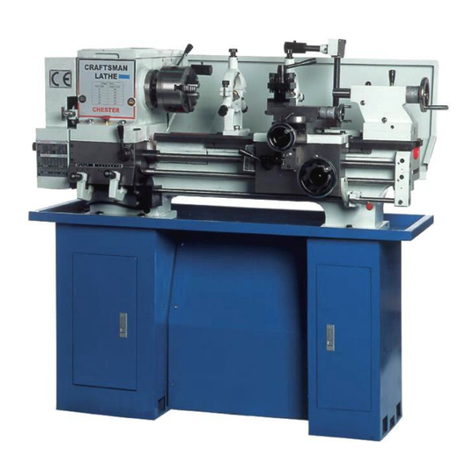
CHESTER Craftsman User manual

CHESTER
CHESTER CONQUEST SUPER LATHE User manual
CHESTER
CHESTER DB11VS User manual

CHESTER
CHESTER DB8VS User manual
CHESTER
CHESTER Crusader VS User manual
CHESTER
CHESTER Cobra Mill User manual
